
Abstract
This article introduces a human–robot interaction controller toward the lower extremity exoskeleton whose aim is to improve the tracking performance and drive the exoskeleton to shadow the wearer with less interaction force. To acquire the motion intention of the wearer, two subsystems are designed: the first is to infer the wearer is in which phase based on floor reaction force detected by a multi-sensor system installed in the sole, and the second is to infer the motion velocity based on the multi-axis force sensor and admittance model. An improved single-input fuzzy sliding mode controller is designed, and the adaptive switching controller is combined to promote the tracking performance considering system uncertainties. Adaptation laws are designed based on the Lyapunov stability theorem. Therefore, the stability of the single-input adaptive fuzzy sliding mode control can be guaranteed. Finally, the proposed methods are applied to the lower extremity exoskeleton, especially in the swing phase. Its effectiveness is validated by comparative experiments.
Keywords
Introduction
Lower extremity exoskeleton is a typical kind of integrated human–robot system which is superior to any autonomous robotic system in unstructured environments that demand significant adaptation. 1 It attempts to combine the strength and endurance of modern robotics with the intelligence and agility of a human operator.2,3 Obviously, it has many potential advantages, such as allowing the user to carry more loads and to traverse irregular terrain surfaces. So, the lower extremity exoskeleton can help individuals employed in particular recreational, occupational, and military activities who often carry heavy loads; it can help fire fighters and other emergency personnel to carry oxygen tanks and other equipment; and it can assist impaired man to walk. 4 In one word, the exoskeleton benefits from the combination of the wearer intellect and machine strength.
To provide effective physical support according to each wearer’s intention, it is necessary to strongly focus on the control system. An important challenge in the exoskeleton system is the ability to sense wearer’s motion intention in time. 5 According to the measurement of the human–robot interaction (HRI), exoskeleton system can be divided into cognitive human–robot interaction (cHRI)-based system and physical human–robot interaction (pHRI)-based system. 6 The cHRI-based system measures the electric signals from the central nervous system (CNS) to the musculoskeletal system of the human and subsequently uses them as input information for the robot controller, such as HAL. 7 However, the pHRI-based system measures change of force or position that result from the motions of the human musculoskeletal system and uses them as input information for the robot controller, such as BLEEX and HEXAR.8,9 The voluntary controller of HAL is developed which uses the wearer’s bioelectrical signals. These signals are based on the myoelectric signal detected on the skin surface of the supporting muscles.10,11 Kwon and Kim 5 proposed an upper limb motion estimation method using surface electromyography (SEMG) and joint angular velocities based on artificial neural network. Although the EMG sensor is generally used to measure muscular activity signals, it is disadvantageous in which it must be directly attached to the skin; it requires high sampling frequencies for signal collection; and it is difficult to quantify the signals.12,13 As a novel control method, sensitivity amplification control (SAC) has been designed in BLEEX. 14 It needs no direct measurements from the wearer or the human–machine interface. However, the system performance is proportional to the precision of the exoskeleton dynamic model which is difficult to depict. 15 Measuring the human–machine interaction force is an intuitionistic and widely used method. Yu et al. 16 have designed a model-free proportional–integral–derivative (PID)-type admittance control for an upper limb exoskeleton to infer the desired trajectory from the human–machine interaction force. To generate the wearer’s intension from the interaction, Lee et al. 6 have adopted virtual impedance control to model the human–machine interaction. Lee et al. 17 also adopted a PI controller to simplify the system controller.
As far as we know, no current technologies can directly measure and extract the human intentions. However, we can infer human intentions from their appearance or motion. In this article, we will design an intention estimator based on floor reaction force (FRF) and force sensor which detects the HRI force.11,18 Impedance control and admittance control are widely used in modeling the human–machine interaction relationship.16,19 However, the former cannot guarantee zero contact force which may cause wearer discomfort. So, the latter is adopted to infer the wearer’s motion intention. Sliding mode control has been used in many kinds of electromechanical systems, such as linear motor,20,21 hydraulic actuator,22,23 active suspension systems,24,25 and teleoperation systems.26,27 Finally, to design a controller which is independent of mathematical model and is easy to accomplish, a direct adaptive fuzzy sliding mode controller based on single input is proposed and a new nonlinear integral sliding surface is introduced to deal with the system chattering. Because the swing phase occupies the 40% of one cycle, effectiveness of the proposed algorithms is verified by experiments in swing phase.
A brief overview of the article is given as follows: in section “Architecture,” the lower extremity exoskeleton is introduced which is developed to enhance the wearer strength. In section “Acquisition of human intent,” the pHRI system is established which is essential to acquire human intent. The relationship between the walking phase and FRF is verified by experiment. In section “Human–machine interaction model,” the admittance is recommended to model HRI and the parameters can be designed based on human impedance properties. In section “Controller design,” a novel direct adaptive fuzzy sliding mode controller based on single input is proposed. To reduce the complexity of the fuzzy rule and decrease the input variables of the fuzzy controller, traditional sliding mode surface
Architecture
The lower extremity exoskeleton is shown in Figure 1, and it comprised two powered anthropomorphic legs, a pair of shoes, and a spine which is designed to carry heavy load. The structure of the exoskeleton belongs to pseudo-anthropomorphic architecture to ensure maximum safety and minimum collisions with the environment and operator which means the structure of exoskeleton is designed by reference to human legs, but does not include every degree of freedom (DOF) of human legs. Overall, the exoskeleton has seven distinct DOFs per leg: 3 DOFs at the hip, 1 DOF at the knee, and 3 DOFs at the ankle. Since the human leg and exoskeleton leg kinematics are merely similar, the wearer and exoskeleton are rigidly connected at the feet, shanks, and upper body. It is unnecessary to actuate all DOFs because most of the power needed for normal walking is in the sagittal plane according to some researches. So, only the freedoms of hip and knee in sagittal plane are actuated by hydraulic. The ankle joint is passive, and the springs are placed to help the foot reset.

Lower extremity exoskeleton.
Acquisition of human intent
An entire walking gait cycle can be divided into the swing phase and the standing phase. Researches have shown that the leg undergoes large motions but it needs relatively small torques which only supports its own weight in the swing phase; the leg executes a small motion but supports the entire torso and payload in the standing phase. Thus, most of the lower extremity exoskeletons have designed hybrid control, such as BLEEX and HAL.28,29 We have uncoupled the acquisition system of human intent into two subsystems. The first subsystem is designed to detect the walking phase, and the second subsystem is designed to detect the HRI force. Conventional researches on human transient walking have made clear that a FRF shift in a sole to one leg is a prior motion to a walk. 7 So, if we can sense the FRF shift induced by the wearer’s intention, we can infer the leg is in which phase. According to some researches, the foot pressures on the front and rear parts are larger than other parts. To detect the FRF in a sole, we have designed the exoskeleton foot and its sensor system as shown in Figure 2.

Exoskeleton foot and its sensor system: (a) force-sensing resistor and (b) footswitch.
The FlexiForce A401 force-sensing resistor (FSR) developed by Tekscan is selected because of its compact size and wide measurement range. To ensure the output voltage has linear relation with the pressure, an analog circuit has been designed and the wearer can change the maximum measurable force. Obviously, the output voltage of the FSR can reflect FRF and the output voltage variation can reflect the pressure change. Considering the complexity of the application environment of the exoskeleton, Ribbon Switch developed by AbleNet is selected as footswitch which is a moisture-resistant switch that is activated by moving the 4 × 0.3-in or 10.2 × 5-cm activation surface in either direction with 4 oz or 110 g of force. The controller records the footswitch’s status, and the current and previous values of the FSR can infer the four possible states of each leg including stance, swing, heel-strike, and toe-off. The rules to infer the leg is in which phase have been formulated and are listed as follows. The leg is considered to be in heel-strike mode when foot contact condition is satisfied

where

where

where

As a sole prototype, we installed one FSR and two footswitches. Figure 3 shows the experiment results. We have identified the four walking phases even if the FRF of the foot front part is omitted.
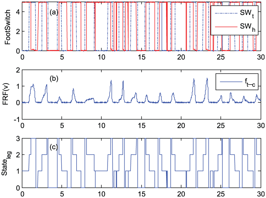
(a) State of the footswitch installed in toe and heel part, (b) voltage of the FSR installed in toe part, and (c) state of the corresponding leg.
In Figure 3, we have defined that number 0 represents swing mode, number 1 represents heel-strike mode, number 2 represents stance mode, and number 3 represents toe-off mode. Based on the first subsystem, we have inferred the walking phase of the human–machine system. To activate the exoskeleton to shadow the wearer with minimum interaction force in swing phase, the second subsystem needs to detect the interaction force.
Human–machine interaction model
As a pHRI-based exoskeleton, force sensor is a commonly used method to detect the HRI force. Figure 4 illustrates that the interaction forces are generated from the connected interface where two 6-axis force sensors are installed and the pHRI is modeled as an admittance relationship.

pHRI model using the admittance relationship.
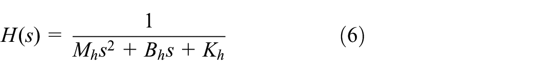
Many studies have modeled the HRI as an impedance model because the impedance control is an excellent controller in hybrid control of position and force.30,31 Theoretically, the input of the impedance is position and its output is force. Admittance control is always seen as the inverse of impedance control while its input is force and output is velocity or position which is more fit to this system. So, we apply the admittance relation in exoskeleton system as follows

where
Each joint of the lower limb can be modeled as a second-order biomechanical system in the musculoskeletal system. 32 Lee has defined the human impedance model as follows
where
In order to find the value of parameters, experiment can be designed to measure and analyze the motions of a human leg using the joint angle and forward kinematics. Relationship has been deduced as follows 33

To improve the operation convenience, we have designed input interface which permits the wearer to adjust the admittance parameters according to wearing feeling.
Thus far, the block diagram to control the swing leg of the lower extremity exoskeleton can be designed as shown in Figure 5.
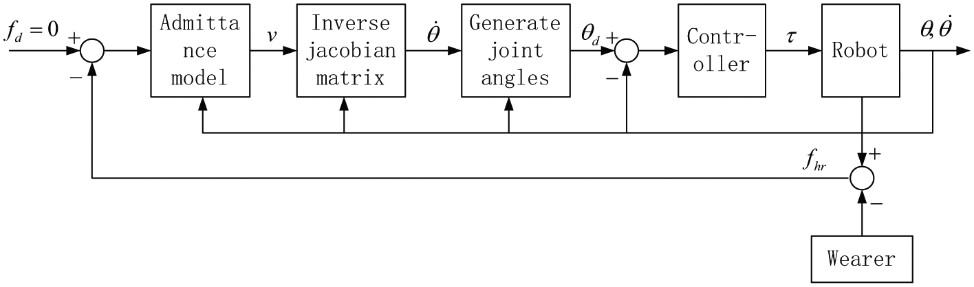
Block diagram of the controller for human–robot interaction exoskeleton.
Controller design
Considering the model error and uncertainties of the hydraulic exoskeleton system, the dynamics model of the swing leg can be written as

where
Because of the difficulties in deriving an exact mathematical model and the complexity of traditional fuzzy controller, we have combined the single-input fuzzy logic controller and adaptive fuzzy sliding mode controller.34,35 An assumption should be pointed out that the desired trajectory of every joint of the lower extremity exoskeleton has been inferred. The tracking error can be defined as follows

where
In traditional sliding mode control, the first step is to select a sliding surface. We have used an improved sliding surface as follows

where
Obiviously,


The number of input variables directly decides the complexity of a convertional fuzzy system. As the dimension and complexity of a system increase, the size of the rule base increases exponentially. By defining the sliding surface as the input variable of fuzzy rules, the fuzzy system is simplified effectively and is easier to implement. The fuzzy rules are given in the following form 36

where

where
From the sliding surface equations (10)–(12) and the dynamic model equation (8), we can infer

Tradition sliding mode control law can be designed as

Since the system dynamics and the disturbance are unknown, the traditional control law is difficult to implement. So, the adaptive fuzzy sliding mode control (AFSMC) is proposed. The control law in equation (14) has been improved by choosing

where
There exists an optimal fuzzy control system to approximate

where

where
Considering the approximation error, switching control is introduced to compensate it. Finally, the control law is listed in equation (20) and the block diagram of AFSMC is depicted in Figure 6


Illustrative diagram of the single-input adaptive fuzzy sliding mode control.
From equation (18), we can get

To infer the control equation, we define

Combining equations (15) and (16), we can obtain

Substituting equation (20) into equation (23), a new equation can be written as

Thus, the Lyapunov function can be designed as

where
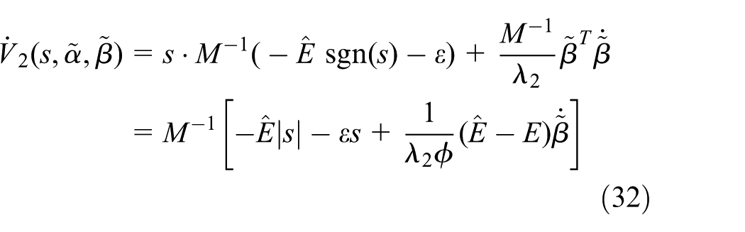
Differentiating equation (25) and using equation (24), we obtain

To achieve


where
Then, equation (26) can be written as
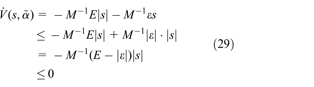
By Barbalat’s lemma, we can conclude that
In equation (28), it is difficult to measure the approximation error E. If a too large E has been determined, a large chattering may take place. To decrease the chatting problem, we adopt fuzzy switching method
37
to approximate

where
To obtain the adaptive law, we define that

where
For achieving

Equation (32) can be written as
By Barbalat’s lemma, we can conclude that
Experiment
To verify the effectiveness of the sensor system in the sole and the proposed algorithm to estimate human intentions based on admittance and single-input adaptive fuzzy sliding mode control (S-AFSMC), we perform experiment on the swing leg of the lower extremity exoskeleton as shown in Figure 1. The lower extremity exoskeleton is a typical HRI system. So, the wearer will first move his leg as the desired trajectory in the swing phase. The controller needs to infer the wearer motion intention and moves the swing leg to shadow the motion in time.
As shown in Figure 5, the human motion intention is inferred based on the force sensor, so the HRI force is measured by the six-axis pressure sensor. The controller proposed in this article aims to minimize the force vector and finally reduced the force vector to zero. Thus we can justify the system’s performance by the amplitude of the interaction force vector. We compared the proposed controller with the conventional fuzzy sliding mode control (FSMC). The parameters in equations (15) and (20) are given as:
As a human–machine system, our aim is to let the swing leg shadow the wearer. So the tracking error and interaction force are chosen to justify the controller. Figure 7 shows the results of the experiment.

(a) Interaction force along the X axis in S-AFSMC and FSMC; (b) Interaction force along the Y axis in INSM and CSM controller; (c) Tracking error of the hip joint in S-AFSMC and FSMC; (d) Tracking error of the knee joint in S-AFSMC and FSMC.
Through Figure 7, it is obvious that the new controller has less interaction force and better tracking performance. The switching control law can compensate the difference between the fuzzy controller and the desired controller. The adaptive law of the switching gain can decrease the chattering problem. The interaction force is obtained by force sensor installed between wearer and exoskeleton and the tracking error is calculated by admittance model and joint encoders. To evaluate the performance of the controller, we have adopted two evaluating indicator: the first is the root-mean-square (RMS) residuals and the second is the maximum absolute value which are defined as

The evaluation results of the controller performance are illustrated in Table 1. Obviously, the RMS value and the maximum value of the two joints gained by S-AFSMC are smaller than the ones gained by FSMC. So the wearer needs less power to drive the swing leg and feels more comfortable by using the S-AFSMC.
Performance evaluation.
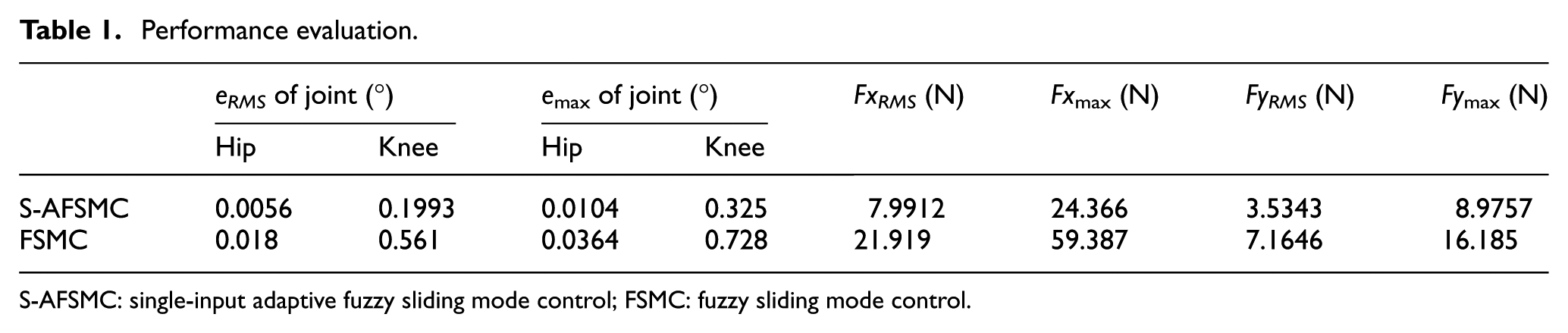
S-AFSMC: single-input adaptive fuzzy sliding mode control; FSMC: fuzzy sliding mode control.
Conclusion
In this article, a sensor system to detect the centor of force is designed in a sole. The estimation algorithm based on FRF which can reflect wearer’s motion status is investigated through the walking experiment. This method can divide walking pace into four modes: heel-strike mode, stance mode, toe-off mode and swing mode. Admittance control is adopted to model the HRI which is normally described by impedance model. An input interface is designed to improve the wearer’s feeling which permits the wearer to adjust the admittance parameters. Further, considering the uncertainties of the HRI system and the hydraulic system model, an S-AFSMC is proposed with a novel nonlinear integral sliding surface. The whole controller contains AFSMC and fuzzy switching control. Both adaptation laws are designed based on Lyapunov stability theorem. Therefore, the stability of the S-AFSMC can be guaranteed. Finally, the proposed methods in this article are verified on the lower extremity exoskeleton, especially in the swing phase. Experiments prove the effectiveness and reliability of the proposed controller compared to traditional fuzzy sliding mode controller. The wearer feels more comfortable to move the swing leg. These methods can be applied in other HRI system.
Footnotes
Academic Editor: Zheng Chen
Declaration of conflicting interests
The author(s) declared no potential conflicts of interest with respect to the research, authorship, and/or publication of this article.
Funding
The author(s) disclosed receipt of the following financial support for the research, authorship, and/or publication of this article: This research work was supported by the Science Fund for Creative Research Groups of the National Natural Science Foundation of China (no. 51521064) and Zhejiang Provincial Natural Science Foundation of China (no. LY13E050001), and Hangzhou Civic Significant Technological Innovation Project of China (no. 20132111A04) and SANLIAN (ShangHai) Group (no. H20131864).