
Abstract
A novel wearable multi-joint teaching device for lower-limb gait rehabilitation is presented, intended to facilitate the adjustment of training modes in unique requirements of patients. A physiotherapist manipulates this active teaching device to plan the personalized gait trajectory and to construct the individual training mode. A haptic interaction joint module that stems from the friction braking principle is outlined here, with an adjustable operating force exerted by pneumatic film cylinders. With dual functions of somatosensory perception and teaching, it provides physiotherapist with a smooth and comfortable operation and a kind of force telepresence. The main contents are elaborated including the structural design and pneumatic proportional servo system of the teaching device and the joint module, operating force control principle, and gravity compensation method. Through performance tests of the prototype, the adjustable operating force has been demonstrated with the characteristics of good linearity and response speed. The results of master–slave control experiments preliminarily verified the effectiveness of the control approach. The research on the novel somatosensory teaching device with master–slave teaching mode has provided a concise, convenient, and efficient means for the clinical application of lower-limb rehabilitation robots, presumably as a new idea and technical supports for the future design.
Keywords
Introduction
Based on the neuroplasticity principle, 1 a lower-limb rehabilitation training robot is a kind of automatic equipment that can recover or rebuild neural pathways2,3 for patients with motor dysfunction. The clinical presentation of a spinal cord injury (SCI) or a stroke comprises motor weakness or complete paresis, complete or partial loss of sensory function. The Swedish therapist Brunnstrom proposed the famous six-recovery-stage theory. Based on this theory, the training has different aims in the early stage of rehabilitation (flaccid paralysis stage), middle stage of rehabilitation (spasm stage), and later stage of rehabilitation (recovery stage). One major principle of neurological rehabilitation is that of motor learning. According to the principle of neural plasticity, repetitive and specific training tasks, which make the cerebral cortex learn and store the correct movement patterns, are important and effective. During rehabilitation, patients have to relearn motor tasks in order to overcome disability and limitations in the completion of daily activities. This is the theoretical basis of rehabilitation treatment. For a robot, the control strategy is provided diversely in different stages of rehabilitation to eliminate abnormal movement patterns. In the early rehabilitation, the passive training mode is usually adopted to help patients according to the predetermined trajectory and improve exercise capacity and reduce muscle atrophy. Then the active assist training mode begins for the patients of the middle recovery stage with moderate strength and relieving muscle spasm. In the later rehabilitation stage, the active resist training mode can be used to encourage patients to participate initiatively. The effect and importance of rehabilitation robots have been internationally recognized.4–8
Giving different state of an illness exhibited by hemiparetic individuals and the different training modes as mentioned above, the gait rehabilitation training robot primarily entails customized designing the parameters including movement trajectory, training speed and strength, and real-time perceiving, adjusting, and controlling. Lower-limb exoskeleton mechanism features of many degrees of freedom, together with the individual and condition differences of patients, so the problems are highlighted about how to accurately plan the correct gait trajectory and how to adjust training modes on time according to the progression. These issues become one of the research foci and technical difficulties of rehabilitation robot.
Most of the typical lower-limb rehabilitation robots in the world are autonomously controlled. The gait training mode planning for them is summarized in two methods, that is, preselected by a physiotherapist and dynamically adjusted by the algorithm. For some representative examples, the horizontal rehabilitation training robot Motion Maker 9 can automatically guide patients along a preselected trajectory to perform passive flexion movement training on hip, knee, and ankle joints. The Lokomat10–12 is a kind of body-weight-supported treadmill training (BWSTT) robot that adjusts the assisted power or reference trajectory by the impedance algorithm according to the patient interaction force. Patients can be made available to active and passive training mode. In the case of the lower extremity powered exoskeleton (LOPES) gait rehabilitation robot,13,14 limb reference trajectory is generated by instantaneous mapping with the healthy limb movement. The feasibility and functional improvements achieved in response to the emergence of such self-control rehabilitation robot; however, the existing technological bottleneck is obvious, that is, the limited adaptability of training mode.
The objective of this research is to develop a gait trajectory teaching device, with which the physiotherapist can directly and professionally teach to the robot and therefore present complex actions and adjust training modes as needed. Through master–slave teaching method, such system may provide the adaptability of the robot-mediated training and improve the treatment quality and efficiency, and decrease the difficulties in control algorithm study and the contradiction between the complex algorithms and real-time control.
Because of the more elaborate actions of the upper extremity and hand, teaching and playback technology is first applied to upper-limb rehabilitation training robot, for example, the flexible force feedback master–slave exoskeleton manipulator developed by America General Electric Company, 15 the wearable master–slave training equipment of upper limbs driven by pneumatic artificial muscles in Okayama University in Japan, 16 and the remotely operated upper-limb training robot of Southeast University in China. 17 But there are fewer applications for lower-limb rehabilitation training. A single-joint ankle-foot orthoses designed by Canada, the Centre for Interdisciplinary Research in Rehabilitation and Social Integration is introduced in the literature. 18 The main cylinder driven by a motor controlled the slave cylinder to drive the orthoses. As described in a literature, 19 a wearable master–slave lower-limb training robot driven by pneumatic artificial muscle achieves the teaching and training for the knee and ankle rehabilitation by sensors feeding back the trainer joint torque to the main control mechanism. In most of the studies mentioned above, the limitations existing in master–slave teaching for the lower-limb rehabilitation training robot can be summarized as follows: (1) the teaching device has the characteristics of complex structure, large quality and high inertia, so the physiotherapist is laborious and feels fatigue quickly, (2) the coordinate of the multi joints is demanded highly which may lead to the insufficient operating smoothness of the device, and (3) the feedback joint torque cannot be directly perceived by the physiotherapist but only as the control signal for the device.
In light of the above limitations, a novel multi-joint wearable teaching device is developed with adjustable operating force, which is exerted by light film cylinders. Based on the gravity compensation control method, a physiotherapist operates the teaching device to plan training trajectory smoothly and comfortably while also perceive the scene interaction force came from patients. In this manner, our research solved the existing problems, namely, the weight, the difficult manipulation of the teaching and the less force feedback to the physiotherapist. He operates the teaching device with the master–slave mode may provide various training modes fast and intuitively. The force telepresence from patients makes physiotherapist better controlling the training intensity and realizing the individual rehabilitation training consultation.
In this article, we elaborate five major contents that have been derived from this research as follows: master–slave teaching system solution, structural design of the multi-joint wearable master teaching device, operating force regulation principle and gravity compensation method, operating force regulation performance experiments, and master–slave control experiments.
Master–slave teaching system of lower-limb rehabilitation training robot
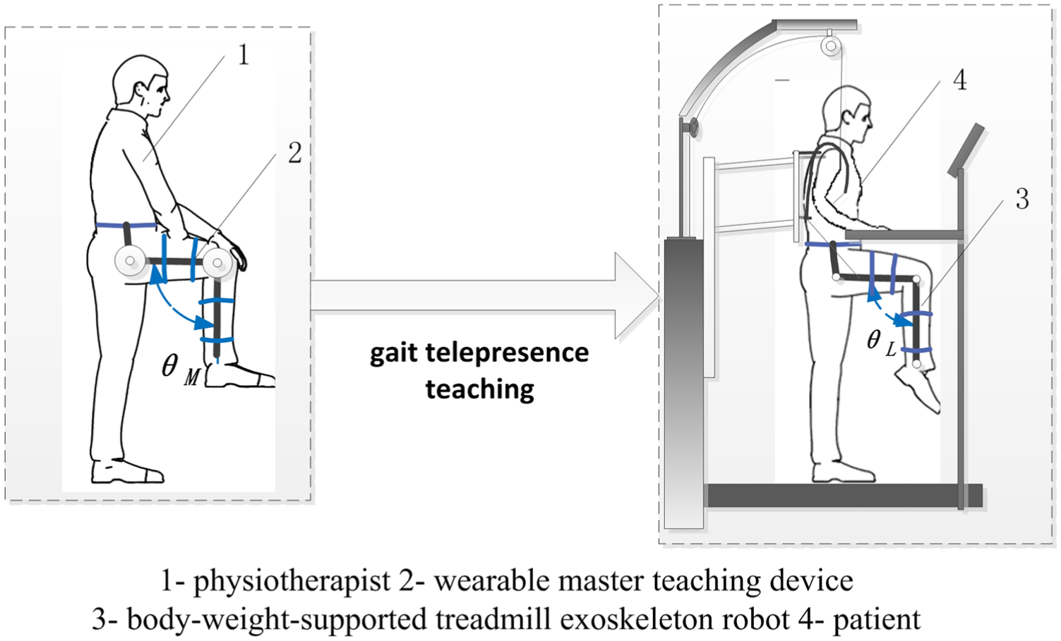
Master–slave teaching system comprises a physiotherapist, a wearable master teaching device, a patient, and a body-weight-supported treadmill exoskeleton robot, as shown in Figure 1.
System overall scheme.
A physiotherapist wears the master teaching device and directly walks to complete the teaching actions in the natural stimulus and by the responses of the human body, instead of the tedious parameter modification and rehabilitation movement plan. Therefore, the gait trajectory conforms to the physiological characteristics, and the robot-assisted rehabilitation is real-time, accurate, smooth, and natural. The knee joint angle θL of robot motion is calculated by the master–slave mapping method from the physiotherapist knee movement angle of θM.
The wearable master teaching device is constructed by the anthropomorphic 2-degree of freedom (DOF) serial-joint exoskeleton. It comprises two joint modules of the hip and knee joints and the links whose length may be adjusted according to the wearer comfortably. Joint modules are driven by film cylinders to realize the adjustable manipulating force and the force sensing telepresence.
The exoskeleton robot automates BWSTT of patients with locomotor dysfunctions in the lower extremities. It comprises a BWSTT system, a gravity adjusting device, a hip adjusting mechanism, and two exoskeletons of lower-limb. The two actuated leg exoskeletons are attached to the patients’ legs. Each exoskeleton has one linear drive in the hip joint and one in the knee joint to induce flexion and extension movements of hip and knee in the sagittal plane. Considering the safety and compliance of contact with the human body, the pneumatic proportional system is adopted as the power for the exoskeleton. According to bionic ideas, both the rehabilitation training robot and the teaching device are designed to match with the range of motion (ROM) of human in the process of walking in order to achieve therapeutic effect. The ROMs of joints in the sagittal plane during walking are listed in Table 1, and the definitions of the joint angles are shown in Figure 6(b) of section “Gravity compensation method for the operating force.”
ROMs in walking of human, lower-limb exoskeleton robot, and teaching device.

ROM: range of motion.
Before rehabilitation training begins, a physiotherapist wears on the master teaching device with single leg and a patient attaches to the slave exoskeleton robot with two legs, by some flexible bands at the waist, thigh, and calf. Links of the devices are adjusted depending upon the height differences of the physiotherapist and the patient, and then the bolts are locked to the correct position. The preparing time is within 15 min. To start the rehabilitation, the parameters to be set are the physiotherapist control force, initial pressure, and ultimate safety pressure. The walking trajectory of both the physiotherapist and the patient are recorded and compared for physiotherapist to adjust the teaching gait spatio-temporal parameters until they are fitted for the patient. With the master teaching device, training mode is of personalized customization according to the patient’s unique condition.
Wearable somatosensory teaching device
Structural designs
This wearable teaching device has the functions of gait teaching and somatosensory perception. The design should be content with the manipulation stability and portability, the wearing comfort and safety, and the sensitivity and accuracy of perception.
The wearable teaching device incorporates two haptic interaction joint modules that provide sagittal-plane flexion and extension movement of the hip and knee joints, which are shown in Figure 2. It is readily attached to the physiotherapist lower limbs by five flexible bands at the waist, thigh, and calf. Depending upon the height differences of the physiotherapist, links are installed with the sliding rail and size adjustment slider. A bolt is locked when the links are adjusted to the correct position. The guard plate separates human lower limbs from the moving mechanism to prevent damage.

Overall structure of wearable somatosensory teaching device.
Joint module designs
In order to provide good operability of the teaching device, and in particular to provide an adjustable force and force telepresence to the physiotherapist, the joint module is developed as stemmed from the friction braking device. The principle is illustrated in Figure 3.

Schematic diagram of joint module.
The pneumatic proportional control system is designed for the joint module. The actuators are two film cylinders controlled by a proportional pressure regulating valve. On the head of the piston rod of each cylinder, there is a brake pad installed. When the controller gives out the control voltage to the proportional valve, two cylinder rods arranged at the opposite sides of the friction disk extend out to push the brake pads to clamp the friction disc. Thus, the friction disc is compacted. If a physiotherapist walks with the device, he should overcome the friction torque Mf between the friction pairs, which gives him the force telepresence. The friction torque Mf varies depending on the amount of pressure p, so the operating force varies to the physiotherapist. The input value of the operating force F0 is determined according to the physical difference of the physiotherapist. He operates joint modules smoothly to generate the joint teaching trajectory which is sampled by the angle sensors in real-time and stored in the controller.
In the process of teaching, the pressure of the pneumatic system of the exoskeleton robot is detected simultaneously. If it is higher than the safe value, it indicates that the movement of the patient is impaired and should not be continued. Then the safe value of pressure plimit applies to the controller to increase the output value p of the proportional pressure value. Accordingly, increased friction damping torque leads to a sudden hindered in operating, so physiotherapist perceives the scene of the patient and stops operation to ensure security. Based on the above principle design and the requirements of compact structure, good rigidity, and lightweight, the structural design of the joint module and the experimental prototype is shown in Figure 4.
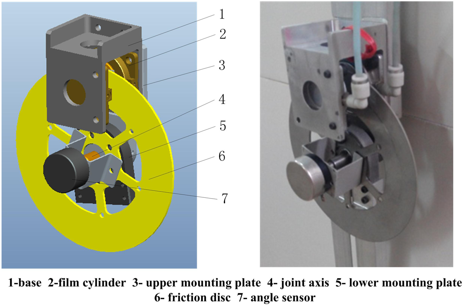
Structure of joint module.
Two film cylinders 2 are installed on the opposing sides of the base 1. Two copper-base brake pads are pushed in opposite direction by the extending rod of the cylinders to generate the normal force on the friction disc 6. The axis 4 is positioned at the rotating center of the friction disc 6, and an angle sensor 7 is installed to detect the rotation angle. The joint modular is connected with the links (as shown in Figure 2) of the upper mounting plate 3 and the lower mounting plate 5. The film cylinder as the friction torque generating element, particularly no transmission mechanism in structure, can be characterized by a compact structure, with lightweight, fast response, and high thrust-to-weight ratio. The copper-base brake pad as the friction plate can be marked by a constant friction coefficient, with considerable linear controllability.
Calculation of joint friction damping torque
Based on the calculation formula of the friction force, the control pressure p of film cylinder can be obtained as


where μ is the friction coefficient, A is the effective action area of film cylinder, and N is the normal force.
According to the braking torque calculation formula, the rectangular brake pad is approximately fan-shaped, as shown in Figure 5.

Diagram of friction damping torque of joint module.
Without considering the gravitational torque of the mechanism, the friction damping torque Mf of the single joint is given as


where R1 and R2 are the distances between the upper and lower sides of the rectangular brake pad to the center of the friction disc, respectively, and Cf is defined as the ratio coefficient. It can be observed that the friction damping torque Mf is linearly proportional to the control pressure p in equation (3) so that the operating torque can be adjusted by changing the air pressure.
By substituted equation (2) into equation (3), Mf is calculated by

Gravity compensation method for the operating force
A gravity compensation component of the controller is intended to remove the gravitational burden of the teaching device mass from the physiotherapist. Note that the operating force is changed continually, since the gravitational torque varies with the joint angles of the mechanism.
This teaching device is a planar two-bar mechanism shown in Figure 6(a), and referring to Figure 6(b), according to the literature,
20
the gravitational torque,

where G1, G2 are the respective gravity of thing and shank links, Gload is the external load of the device, x1, x2 are the distances from the center of mass of thing and shank links to the respective joints of hip and knee, l1, l2 are the respective length of the thing and shank links, and θ1, θ2 are the respective joint angle of hip and knee.
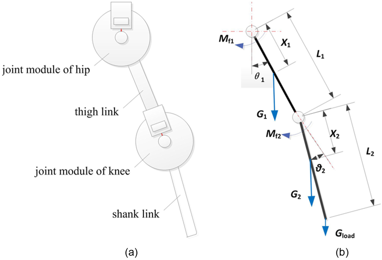
Force analysis of the teaching device: (a) schematic diagram of the mechanism and (b) equivalent force diagram.
The operating torque of joint module,

From equation (6), it is shown that the gravitational torque is varied with joint angles. If the constant pressure is applied to the film cylinder, the operating torque is unstable because of the change of gravitational torque. In order to compensate for the gravitational torque, according to equation (3), the actual compensation pressure

In matrix form, the joint-space dynamics equation can be written as follows

where
When the output pressure is changing with joint movement angles of the teaching device as equation (8), the gravitational torque is eliminated. And the terms of
Operating feature experiments and safety analysis of the teaching device
The previously described wearing somatosensory teaching device is developed, as shown in Figure 7. To verify the functions of the developed system, and the proposed method in general, the experiments of linear controllability and gravity compensation are carried out on the prototype.
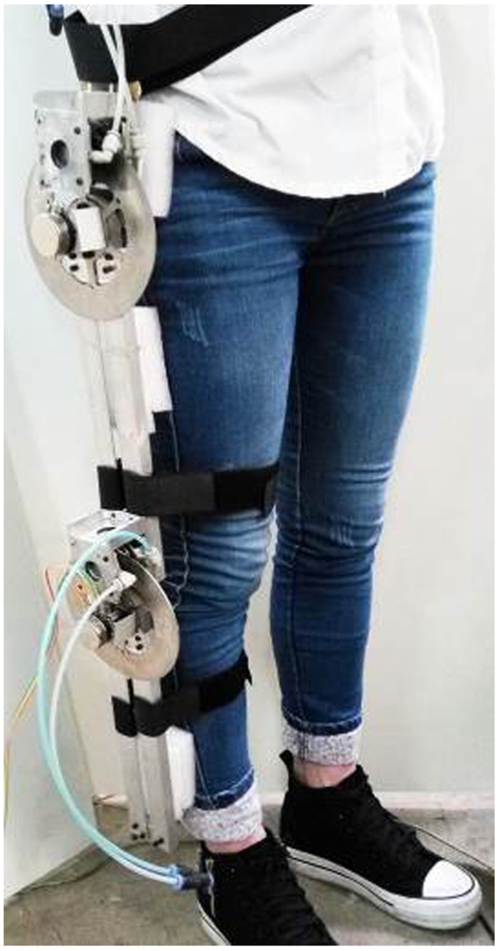
Prototype of wearable somatosensory teaching device.
Linear controllability experiments of the operating force
Described as equation (2), the operating force is proportionate to the control pressure of the cylinder. Prior to the experiment, the link is vertical downward and joint angle remains 0° unchanged, so the gravity has no impact on the operating force. The operating torque is measured during the pressure changed from 0 to 0.5 MPa. Figure 8 shows the relationship curves between the control pressure and the operating torque of the joint module. The measured curve coincides basically with the theoretical curve. The error is smaller with a pressure range between 0.2 and 0.4 MPa. As is evident in Figure 8, the operating force is of good linear controllability.

Relationship curves between control pressure and operating torque.
Gravity compensation experiments of the operating force
In the case of the hip joint, the effectiveness of gravity compensation method is validated by changing the joint angle between −80° and 80°. When the hip angle changes, the operating torque is influenced by the gravitational torque. The measured curve without gravity compensation is shown by the dotted line in Figure 9(a), which can be seen that the operating torque varies from 1.8 to 6.7 N m.

Influence curves of gravity compensation on operating torque of hip joint: (a) curves of operating torques and (b) pressure curve with gravity compensation.
The operating torque changes with the angle, which interferes with the operation of the physiotherapist and leads to the teaching process not smooth and steady. When the setting value of Mjoint is 3.5 N m, the working pressure is calculated by equations (4), (6), and (8), and the curve is shown in Figure 9(b). The film cylinder is driven according to the varied pressure in Figure 9(b) provided by the proportional valve, and then the operating torque is measured, as shown in Figure 9(a) by the solid curve, which can be seen that the torque is almost constant at 3.5 N m with the error ranging from roughly −0.2 to +0.3 N m, about 5.7%–8.6% of the full scale (FS).
The reason for the errors lies in the fact that the working pressure can only be discretely output according to the curve and there is no compensation for the friction of the mechanism. However, the range of operating torque error is small for the human sensing of the physiotherapist, so the stability of the operating torque with gravity compensation is verified.
Safety analyses
Since the master teaching device is a wearable device, it is necessary to make sure that the operating torque does not harm the human body. The pressure of the air supply is turned from 0.3 to 0.7 MPa; relevant operating torque values are summarized in Table 2, according to the range of motion (ROM) of human joints.
Actual operating torques of different pressures.

As is evident in Table 2, the actual operating torque is not more than 10 N m within the scope of human ROM according to the design parameters of this system. In particular, the ROMs of the hip and knee for patients in rehabilitation training are lower than that of a normal human, so the safety is guaranteed with the mechanism and the pneumatic drive system design. Second, because of the passive friction characteristics, the friction damping torque is produced only when the physiotherapist operates. Friction cannot be obtained under stationary state and therefore does not exert force for the physiotherapist. Finally, there is an emergency vent valve in the system, and when the physiotherapist feels unwell, he can press a button to release pressure and the friction torque decreases quickly.
From the above experimental and theoretical analysis, the actual operating torque is related to the locations of brake pads, friction coefficient, the area of the cylinder, and the system pressure. More reasonable design parameters can be adjusted through clinical trials.
Master–slave teaching and playback experiments
Lower-limb rehabilitation training system is implemented with a teaching device as the master and a body-weight-supported treadmill exoskeleton robot as the slaver. Experiments were performed with the testing system shown in Figure 10(a). The hip angle of the master is denoted as θM1 (defined extension as positive direction and flexion as negative), as well as the knee angle of the master is denoted as θM2 (defined flexion as positive direction and extension as negative direction), as shown in Figure 10(b).

Prototypes of the master–slave rehabilitation training system: (a) testing system and (b) definitions of joint angles of the teaching device.
The physiotherapist wears the master teaching device and directly walks to generate the gait trajectory in the natural mode of the human response to stimulus. By the master–slave mapping algorithm, the designed joint angle θs0 and the joint velocity

where Kp is the proportional gain of position error and Kv is the velocity error gain.

Master–slave control algorithm diagram.
Single-joint experiments in unloading state
In order to verify the effectiveness of the mechanism and the control method, the hip joint modular of the master teaching device is operated continually and the hip joint movements and playback processes of the slave robot are recorded. The PD controller of the slave robot is also tested with Kp = 0.035 and Kv = 0.002. Due to the compressibility of air as working fluid, the response of a pneumatic system to a change in the reference trajectory, the slave robot has a slight time-lag (<0.5 s) allowed by the rehabilitation training while the trajectory is basically the same as the master in a gait cycle, as shown in Figure 12(a). In Figure 12(b), the following hip joint angle curve of the slave robot is accurate relative to the target curve of the master in multigait cycles, but there is also a 0.5 s time-lag on the whole. The errors of joint angle (maximum 3.5°) are caused by the computational accuracy of the master–slave mapping and motion matching algorithm, and the current simple control strategy of the lower-limb rehabilitation training robot. In the playback stage, the movement of the slave device is consistent with the teaching trajectory, and no loss occurs.

Master–slave teaching and playback curves of hip joint: (a) teaching in a gait cycle and (b) teaching and playback in multigait cycles.
Double joints coordinated movement experiments
Double joints coordinate master–slave teaching experiments are carried out when the physiotherapist wears the master teaching device, and the two weights of 2.5 kg are fixed on the centers of the thigh and shank segments of the slave robot, respectively, to simulate patients legs. For the hip PD controller, the parameters are set as Kp = 0.035 and Kv = 0.0022, while Kp = 0.04 and Kv = 0.002 for the knee PD controller. Under the load state and with different working pressures, the dual-joint coordinated test curves are shown in Figure 13. Due to the influence of the load, the curves show chatter in the joint angle and are not as smooth as that of the no-load state. The hip joint curve is smoother than that of the knee joint. The average of time-lag of the hip joint is 1 s while the maximum time-lag of 1.4 s occurs when the joint is in the reverse motion at the pressure of 0.4 MPa, as shown in Figure 13(a). The reason for this phenomenon is that joint rollback is realized by reversing the cylinder, so reversing time of the cylinder causes the system to a larger time-lag. When the working pressure is improved to 0.5 MPa, the time-lag of the knee decreases, and the average value is 0.4 s. However, there is no improvement in the hip joint, as shown in Figure 13(b).

Teaching curves of dual-joint coordinate motion in loading state: (a) working pressure of 0.4 MPa and (b) working pressure of 0.5 MPa.
Discussion
The load has an influence on the master–slave control performance both of the hip joint and the knee joint, in particularly, the time-lag and position error are increased. At present, only PD control is applied to the system. By improving the control strategy, such as adaptive control and other advanced control algorithms, the position error can be lower.
In the test, the fixed load we presented had less impact on the hip joint than that of the knee joint. If patients are trained in the rehabilitation, as a variable load, we considered to construct two pressure circuits for the knee and hip joints with different working pressure control loop to reduce the effect, and to add adaptive control of the driving force.
When the work pressure is increased from 0.4 to 0.5 MPa, the dynamic characteristics of the knee joint of the robot are improved. Accordingly, under the condition of larger variation of load, if the driving force is increased, it is beneficial to improve the position precision of the master–slave control system.
The time delay of the slave robot in the experiments has no impact on patient safety because only the starting time is later than the teaching device. But the time delay of the joint rollback caused by the cylinder reversing can bring a sense of non-fluency for the patient in the gait training. Therefore, we intend to introduce velocity feedforward algorithms to solve the problem.
The partial lack of sensibility has to be taken into account when a patient with a neurological condition is trained. Patients who experience an impairment of their cognitive function might not be able to better cooperate with a robotic device. These factors may present as the time delay, position error, or force noise signals, but the experiments carried out at present are all fixed load bonded on the robot links, which cannot verified the impacts of these factors. Next, we will carry out the clinical trials and the patient-robot interaction force will be measured and used as the force feedback to the controller. We will present an admittance controller and a compensator of position to avoid the impacts caused by patient hesitations.
Through the above experiments in sections “Operating feature experiments and safety analysis of the teaching device” and “Master–slave teaching and playback experiments,” the mechanical characteristics of the wearable somatosensory teaching device, the feasibility, and effectiveness of master–slave control method are verified. It is helpful for our further researches on the master–slave control for different rehabilitation modes (such as passive, active training).
Conclusion
Rehabilitation is a typical human–robot cooperation and coexisting process where the physiotherapist, patients, and rehabilitation training robot are closely related to each other. A novel wearable 2-DOF somatosensory teaching device driven by the film cylinders is proposed and experimentally evaluated. The results indicated that the teaching device can be manipulated smoothly and lightly, with the characteristics of safety and flexibility. The lower-limb rehabilitation training robot is constructed based on the pneumatic proportional driving system and the master-slave teaching control method is adopted.
Compared with two respective BWSTT robots, Lokomat and LOPES, the summary of the proposed solution is listed in Table 3, where our master–slave teaching system of lower-limb gait rehabilitation training robot is named as HAUST robot in the table.
Summary of BWSTT-type gait rehabilitation training robots.

DOF: degree of freedom; HAUST: Henan University of Science and Technology.
Robots can measure far more accurately and free from subjective perception than human therapists. However, robotic devices usually measure forces only in one plane or DOF. A therapist is able to perceive forces more naturally, and to complete the teaching actions by the human response. As such, the physiotherapist provides personalized gait rehabilitation trajectory to the patients based on the force sensing telepresence, medical experience, and consciousness of natural walking. The teaching process is natural and personalized. Physiotherapist direct teaching provides a concise, convenient, and efficient means for the clinical use of rehabilitation training robot, and the human–robot cooperation is simple and coordinated.
On the basis of the present studies, the system still has some disadvantages and improvements in the next research. It will increase the ankle joint mechanism to provide the gait teaching finer and improve the recognition and correction of error data in misoperation. Future work will also involve creating an adaptive controller for the robot and conduct clinical trials to optimize the system.
Footnotes
Appendix 1
Academic Editor: Francesco Aggogeri
Declaration of conflicting interests
The author(s) declared no potential conflicts of interest with respect to the research, authorship, and/or publication of this article.
Funding
The author(s) disclosed receipt of the following financial support for the research, authorship, and/or publication of this article: This study was supported by the “Research on key generic technologies of pneumatic gait rehabilitation training robot” project (172102210036) granted from “Project of science and technology of the Henan Province” and the “Research on bionic driving mechanism and control strategy of non-skeletal waist power assisted robot” project (162300410082) granted from “Program for the Natural Science Foundation of Henan Province.”