
Abstract
Industrial and service robots deal with the complex task of grasping objects that have different shapes and which are seen from diverse points of view. In order to autonomously perform grasps, the robot must calculate where to place its robotic hand to ensure that the grasp is stable. We propose a method to find the best pair of grasping points given a three-dimensional point cloud with the partial view of an unknown object. We use a set of straightforward geometric rules to explore the cloud and propose grasping points on the surface of the object. We then adapt the pair of contacts to a multi-fingered hand used in experimentation. We prove that, after performing 500 grasps of different objects, our approach is fast, taking an average of 17.5 ms to propose contacts, while attaining a grasp success rate of 85.5%. Moreover, the method is sufficiently flexible and stable to work with objects in changing environments, such as those confronted by industrial or service robots.
Keywords
Introduction
Robotic grasping is an important topic in industrial and service robotics with a broad multidisciplinary approach, such as motion planning, control and perception, among others. 1 The grasping problem focuses on determining a set of contact points on the surface of the object in order to automatically carry out a manipulation task, either using robots with grippers or multi-fingered hands. 2 Computed contacts can be evaluated with multiple metrics. 3,4 In short, they should provide stable grasps by considering the kinematic constraints of the robot.
The field of robotic grasping when robots operate in unknown environments or under changing conditions is still being researched. These situations are currently becoming more frequent in a wide variety of applications within Industry 4.0, such as the flexible manufacturing processes in smart factories, 5 the restocking and warehouse tasks in smart stores, 6,7 automated deliveries from distribution centres and logistics 8 or household assistants, 9 among others.
In all of these applications, robots still confront difficulties when attempting to grasp objects of different shapes, sizes and materials. Even more if the object is unknown to the robot and it does not have prior knowledge of it. Maintaining a database of known objects is a complicated task, since there are many possible configurations as regards the geometry and appearance of the same item. Even when objects are known, the grasping task is still made difficult by issues like the light conditions, the variety of positions that can be adopted by them and the changing orientation during the grasp.
In order to attain robots that can autonomously perform grasps, it is often used information acquired from different sensors integrated as part of the autonomous robotic system. 10 Thereby, the autonomous manipulation can exploit force and torque data, 11 vision systems, 12 tactile information 13 or combine several of them. In this work, we exploit a three-dimensional (3D) vision sensor.
Related work
In our work, we use a single point cloud with a partial view of the objects present in the scene. Moreover, the objects are unknown: they have not been previously recognized and we do not have a 3D computer-aided design (CAD) model to compute candidate grasping points. Our main goal is to estimate a pair of 3D-located points on the surface of the object in order to enable a robotic grasper (either a gripper or a multi-fingered hand) to perform a stable grasp of the object in the scene with no information other than the point cloud.
Previous vision-based grasping systems proposed in the literature usually take multiple views to detect and identify the object in front of the robot. Once they recognize the object and its pose, they proceed to calculate potential contact points using stored 3D CAD models. Some recent solutions find these grasping configurations by using machine learning techniques trained on large data sets or in simulation.
Salichs et al. 14 discuss the decision-making process in robotics. They state that there are different levels of autonomy given the degree of high-level decisions that are made by the robot. When objects are reconstructed to retrieve grasps from 3D models, the robot does not have any level of autonomy as regards the grasp computation because this is delegated to an offline computation. As for the machine learning cases and, more remarkably, in reinforcement learning approaches, the authors leave the whole decision process to the machine and cannot predict its behaviour. In our case, we have decided to provide the robotic system with the tools required to discover how it should approach objects and grasp them. The system is autonomous, but we know what strategies it uses and how it behaves.
In this work, we focus solely on those vision technique-based approaches that are used to obtain object information and calculate the grasping contact. We consequently identify three main different approaches for the problem of robotic grasping, depending on the level of autonomy or the contact calculus methodology.
Object reconstruction and template grasp retrieval
Some authors have dealt with this problem by reconstructing meshes, given multiple views of the object, and then computing the grasping points on CAD models. For instance, Varley et al. 15 proposed a system that segmented an input point cloud in order to find the objects present in the scene. After reconstructing them as meshes, they ran the GraspIt! simulator 16 that calculated the best grasp configuration for a three-fingered robotic hand. Some authors have proposed approximating the object’s surface: completing its symmetries 17 or regenerating a similar model using Gaussian Processes. 18 They then searched for the final grasp pose by optimizing a function that evaluates the distance between the centre of the reconstructed object and the centroid of the polygon formed by the fingertips.
With regard to template grasps retrieval, some authors have proposed to use a database of pre-calculated grasps on segmented meshes of real objects. 19 During the real execution of the system, the robot decomposed the RGBD image of the object into meshes of primitive forms like cylinders. The authors then matched these parts against template grasps. Similarly, Jain and Argall 20 described an algorithm to match whole real objects against geometric shapes (i.e. spheres, cylinders, boxes) rather than parts of them. Once they found the corresponding primitive, the authors predefined a set of fixed strategies that could be used to grasp those shapes.
This methodology can work to grasp known objects but it does not generalize properly to unseen ones. This is owing to the fact that it is limited to a previously recorded set of shapes. In addition, it needs multiple views in order to reconstruct the object and match it against a CAD model. In a real scenario, such as that of a restocking robot, these are restrictions that would result in the robot being stuck in the case of confronting an unknown object or if it cannot move to take sufficient multiple views.
Machine learning
The latest advances in machine learning have led to a new set of solutions that consider the problem of finding the best grasping pose as a classification task. Firstly, Jiang et al. 21 introduced the idea of the grasping rectangle: an oriented rectangle in the two-dimensional (2D) image space, in which two of the opposite borders corresponded to a gripper’s plates and the other two represented the gripper’s opening. The authors used RGBD labelled images to find the best ranked grasping rectangle using a support vector machine. In recent years, this grasping rectangle has been extensively researched using more complex techniques. For instance, some authors have explored the use of convolutional neural networks (CNNs) to learn this representation. 22 –25 They input whole RGBD images or subsets of these channels in order to train networks that generate grasping rectangles and rank them.
Although these approaches have proved to achieve high grasping rates, they require a significant amount of correctly, labelled data and also enormous computation capabilities and amounts of time. This is necessary to fine-tune both the learning architectures and their hyper-parameters in order for them to generalize well to unknown objects. Some authors have collected data sets with synthetic RGBD images and point clouds so as to overcome this problem. 26 Some works have collected thousands of real robotic grasping attempts by running several robots for hundreds of hours. 27,28 From our point of view, all of this requires a hardware architecture that is limited to just a few researchers.
There are also solutions that apply reinforcement learning. Some approaches explored the possibility of learning to grasp through the use of a real robot. 29 –31 This led to long, time-consuming experiments with no prior knowledge of possible future success. Following works attempted to deal with this problem by performing the reinforcement learning on a simulator. 32,33 Some authors have processed simulated images with adversarial methods 34 –36 to produce life-like images of the robotic grasps. These methods no longer require labelled data sets but they struggle with problems like transferring the learnt grasping policies to the real world and to visually changing environments.
Point cloud analysis
Three-dimensional point clouds have some advantages over 2D RGBD images, like containing rich information about the volume, surface and location of the objects. In this area, Richtsfeld and Vincze 37 were one of the firsts to propose a method for computing a set of grasping points using this information. The authors first searched for the top planar surface of the object and then selected the closest point to the centroid at the edge. The second contact point was then located on the opposite rim. Later on, Gori et al. 38 proposed a whole pipeline for finding triplets through the use of a variant of the Discrete Particle Swarm Optimization algorithm. The authors defined a set of specific properties that the triplet should satisfy, related to the robotic hand in use, in order to retrieve stable grasps from incomplete 3D point clouds.
More recently, ten Pas et al. 39 –41 computed grasping candidates by locating antipodal configurations on the object in order to produce antipodal grasps using a gripper. Therefore, they were able to find points at which an enclosing gripper would apply opposite, colinear forces to perform stable grasps. They further developed this method in such a way that a representation of the surface of the object, contained within the enclosing antipodal configuration, was introduced into a CNN that ranked whether or not it was in frictionless equilibrium and improved the grasping success rate.
Last, Zapata-Impata et al. 42 presented another approach in which a set of contact points were found by doing a geometrical analysis of a single point cloud. Firstly, their method segmented the point cloud to detect the objects present in the scene, which were unknown. For each object, the authors approximated their main axis as well as their centroid. Using this, their proposal sampled potential grasp points that were evaluated using a set of constrains, which theoretically guaranteed the most stable grasp.
For our work, we chose to use 3D point clouds because we find advantages in the use of this type of structure for robotic grasping. 3D point clouds contain geometric information about the objects, like the curvature of their surface. It is of great value for computing grasping points getting to know whether the potential contact areas are highly curved, since that could mean a less stable surface. In addition, knowing the location of the object in the 3D world can solve problems like finding a 6D pose for the gripper so that it can perform the computed grasp. Finally, if one uses the volume information captured in the 3D point cloud, it would be possible to know whether the computed grasp wraps the whole object. For all of these reasons, this article is developed on top of the 3D geometric method introduced by Zapata-Impata et al. 42
We improve the ranking function they proposed in order to find grasps that are more promising. Moreover, we propose a way of adapting the pair of contact points calculated to grippers as well as multi-fingered hands. In contrast to their work, we analyse the grasping computation in a real system and test it on a real set-up grasping everyday objects. All in all, the proposed method offers advantages over previous approaches and overcomes some of their limitations. These are the main contributions of this work: We define an improved version of the ranking metric introduced in Zapata-Impata et al.
42
for evaluating a pair of contact points in order to find the best grasp configuration. It is parameterized by the morphology of the robotic hand in use so it is adaptable to different hands or grippers. Extensive real experiments are carried out to prove the effectiveness of the grasping computation. We demonstrate that the proposed method generalizes well to diverse objects and geometries. To achieve this, the proposed method is integrated in a real robotic system. The proposed method is fast so it can be used in real-time scenarios. It consists of a set of straightforward generic rules that can be rapidly computed. As a consequence, our method spends half of the time processing a scene than the current state of the art. We explore how the computed contact points can be adapted to multi-fingered hands, demonstrating in real experiments that this method proposes feasible grasps for these kind of morphologies.
The remainder of the article is organized as follows: Section ‘System architecture’ describes the data acquisition system, the real robotic set-up used and their constraints. Section ‘Grasping points computation’ details the method used to segment the input cloud, find the candidate grasping points areas and rank potential contact points. Moreover, this section details how we find the grasper’s pose. Section ‘Grasp execution system’ explains the methodology followed to execute grasps in the real set-up. Section ‘Experimentation’ shows the results obtained after grasping a set of everyday objects. Finally, section ‘Conclusions’ presents our conclusions.
System architecture
In this section, we describe our robot set-up used to carry out experiments in the laboratory, the RGBD camera that recorded the input point clouds, and the objects that we can process and grasp, which are influenced by the hardware.
Data acquisition
We carry out this work using an Intel RealSense SR300 depth camera, which projects a coded infrared pattern in order to calculate depth images and generate point clouds. This camera has an optimal recording distance of between 0.2 and 1.5 m. Due to its technology, we are constrained to record opaque objects and to avoid dark colours. Because of the wavelength of the light emitted, the camera does not properly see translucent or dark objects since they reflect, refract or absorb the light.
Regarding the stiffness of the objects, we do not work with highly deformable bodies like pieces of clothing. These are usually grasped by following different strategies, such as detecting the points which the gripper should pinch. 43 In addition, their dynamics require further supervision of shape deformation after the first grasping contact. 44 Nevertheless, our proposed grasping points can be used as an initial pair of contacts for this type of objects.
Robot set-up
In our laboratory, we have a robotic torso that comprises two robotic arms and two robotic hands. We have tested our algorithm using the left-hand side of the robot. It consists of a Mitsubishi PA-10 industrial robotic arm with 7 degrees of freedom (DoF). Its end effector is an Allegro robotic left hand, which is a four-fingered hand that has 16 DoF, four for each finger, and is capable of holding up to 5 kg. Figure 1 shows the robotic arm and hand configurations. There is a table in front of the robotic torso on which we place the working objects. The whole robot is shown in the bottom-right corner of the figure. OH stands for the reference frame of the hand, OC is the reference frame of the camera and OW is the world’s origin.

Left arm of our robot comprising a Mitsubishi PA-10 and a left Allegro robotic hand. In the bottom-right corner, a view of the whole robot and the working table.
The visual system for 3D robot positioning uses an eye-to-hand configuration in which the camera is located externally to the robot. The reason for having our camera fixed in this position and not placed like a head on the top of the torso is to ease the configuration of the arm. If the camera is on the top of the robot acting as a head, the point of view will produce grasping points in front of the torso. Since the PA-10 is a long arm, its working space would be limited if we were to constrain it to grasp objects frontally because most of the configurations of the arm would collide with the torso. By placing the camera on the left, it will be more feasible for the arm to reach the proposed contact points.
Grasping points computation
In order to compute a pair of grasping points, we first segment the input point cloud to find the objects that are present in the scene. For each object, we then find two candidate areas on their surface. We rank combinations of points from these two areas using a custom function. The best-ranked pair guarantees the most stable grasp configuration, given the view conditions. The entire method described during this section is graphically summarized in Figure 2.

Summary of the proposed method for computing a pair of contact points. Symbols are explained through the section. Scene segmentation: (a) original cloud and (b) segmented objects. Grasping areas: (a) cloud of the object, (b) centroid, axis, cutting plane and cutting cloud, (c) initial points and grasping areas. Points ranking: (a) curvature and normal vector of potential points, (b) samples of evaluated pairs of contacts, (c) best ranked points and connecting line.
We receive a single point cloud ℂ containing the scene of the objects that we want to grasp. Let
From here, the remainder of the method description focuses on working with one object. By repeating the following steps with every point cloud
Grasping areas
It is necessary to find a grasping area for each of the two contact points at which the candidate grasping points will be located. Let
We define two geometric rules to find the grasping areas in the cloud
Let If Otherwise, the object is standing up or lying on the table oriented towards the ZC axis. Therefore, the candidates will be in opposite areas along the XC axis.
By simply defining these two rules, we find the grasping areas for any object in any orientation. We avoid the YC axis because it is parallel to the normal vector
We now search for the initial candidate grasping points
These spheres initially have a radius that is equal to
Grasping points ranking
Before evaluating the contact points, we create voxels in the clouds
Let
Distance to the cutting plane γ
This plane is cutting the object in half through its centroid c, so the closer the grasping points
Curvature of the point
A grasp is more likely to be stable if we perform it by placing our fingertips on flat areas instead of on highly curved points. We introduce this into our algorithm by measuring the variation in position between a point and its neighbours, a feature that is called curvature. This is estimated by applying the method presented by Pauly et al.
48
We first compute the covariance matrix of the points within a sphere from the reference point, the point to which we are measuring its curvature, using PCA. Then, we obtain the eigenvalues and eigenvectors from Singular Value Decomposition. The curvature can accordingly be computed as
Antipodal configuration
An antipodal grasp configures the hand in such a way that it applies opposite and collinear forces at two points on the surface of the object. A pair of contact points with friction could approximate an antipodal grasp if these two points lie along a line parallel to the direction of finger motion. In order to approximate this in our ranking function, the angle

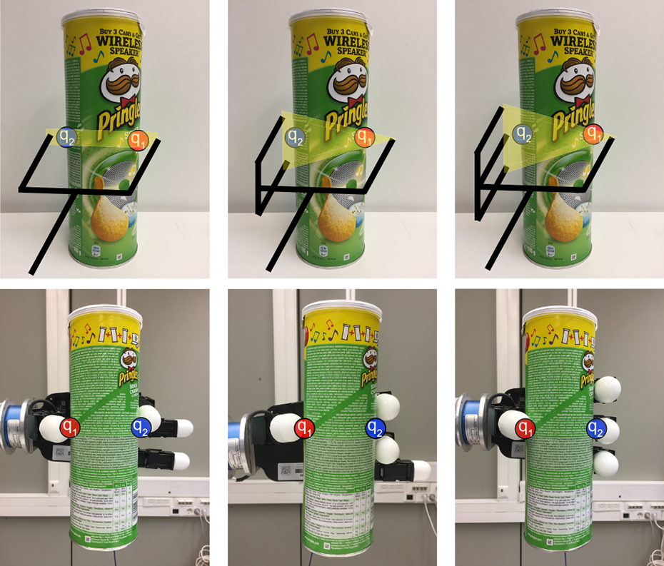
Representation of how the antipodal configuration is approximated in this work using
Perpendicular grasp
Since our grasping areas are spherical, there are chances that the grasp configuration Θ will not be parallel to the cutting plane γ. We want our points to be at equal distances from it so the grasps are perpendicular to the main axis
Taking these four factors into account, we propose the following ranking function to assess the potential stability of a grasp configuration Θ

Configurations ranked with our function equation (1) can have a maximum value equal to 8.0, if
Curvature and normal directions are evaluated by
These subfunctions are weighted in order to balance their influence with
Finally, we also take into account the maximum amplitude of the grasper in use in order to select the best grasp configuration. During the ranking of potential points
Estimation of hand pose
We propose the two best points of contact that can be used straightforwardly with grippers moving each of the plates towards each proposed contact. The Allegro hand we use has four fingers, one of which acts as the thumb. In order to perform three-fingered grasps, we take the following criterion: one of the contact points corresponds to the place the thumb must reach during a grasp, while the other contact point remains between the first two fingers (index and middle). This means that the first and second finger wrap around the second contact point. Figure 4 shows an example of this grasp configuration.
Adaptation of our two best contact points for two-fingered grasp (i.e. grippers), three-fingered grasp and four-fingered grasp.
Four-fingered grasps would follow a similar criterion. However, in this case, the second contact point corresponds to the place the second finger (middle) must reach, while the first and the third finger wrap around it. Figure 4 shows an example of this. In this work, we perform three-fingered grasps so we do not make use of the third finger. We have made this decision owing to the size of the Allegro’s fingertips, which are large. Using four fingers would lead to issues with some of the small objects tested, like one of the wrapping fingers not making contact with the object.
Once we have found the best grasp configuration, we determine the pose our hand should acquire in order to perform a grasp on these such points. This is done by using the main axis
Let

Grasping pose of the hand estimated from the contact points: (left) seen during the simulation and (right) in reality.
Last, this reference frame is translated backwards from the object so that the closing movement of the hand places the fingers in the desired positions. To perform this, we measured the distance between the fingertips and the palm of the hand, where the reference frame is located, during a closing movement. Thus, knowing the distance between q1 and q2 would allow us to know the position of the hand so that the fingers would contact at the same time the desired points, applying collinear forces. Consequently, the built frame is translated backwards (on XH axis) a distance that depends on the morphology of the hand in use. Figure 5 shows this position both in simulation and in reality.
Grasp execution system
This work has been developed under the robot operating system (ROS) framework and programmed in C++. The whole system is integrated into ROS, thus enabling us to have multiple nodes running simultaneously and sharing information among them. The grasp computation node is available at https://github.com/yayaneath/GeoGrasp. In addition, our robot model is defined in URDF files so we can load it and simulate grasps before sending them to the real robot. We have done this by also integrating the MoveIt! package 49 into our workflow in order to simulate the robot and plan trajectories that take into account collidable objects. All these components allow us to work in a real scenario, as seen in Figure 1, but to model the environment, as shown in Figure 6, in order to plan and virtually perform grasping trajectories.

Environment used to simulate grasps using MoveIt! Right picture shows a planned trajectory with collidable objects on the table.
Solution architecture
We have integrated the process in charge of reading a published point cloud and computing grasps into a single node, making use of the proposed contacts computation. We call this node pointcloud_listener. It executes our proposed method and creates a custom ROS message called GraspConfiguration for each of the segmented objects in the scene. This message holds the information needed to perform a grasp:
A second node, called allegro_plan_grasp, subscribes to the topic in which SceneObjects messages are published. This node reads the SceneObjects message and publishes an approximated collision box for each object in the MoveIt! planning scene. Since each GraspConfiguration holds the cloud of the K object
The allegro_plan_grasp then proceeds to plan a grasp on the closest object to the camera: the object located furthest to the left with regard to the robot. We have employed this criterion because we are using the left arm so grasping these objects first will ease the planning of collision-free trajectories. Moreover, if we first remove the objects that are closest to the camera, it will be possible to see the rest of the objects in the back better. Finally, this node is also responsible for calculating the pose of the hand used to grasp the object, using the method described in the previous section. In Figure 7, we display a scheme that represents our main nodes and their interactions through the use of ROS.

Architecture of the solution implemented.
With regard to planning the trajectories, we have several planners available in the MovetIt! package. After testing them, we decided to use the RRTConnectkConfigDefault planner because it was able to find good trajectories in a short amount of time.
Grasping steps
Before beginning this process, we configure the arm in a preparing position in which it is ready to move towards the table but it is not visible from the camera. In consequence, the arm and the hand do not interfere with the grasping point computation. This position is displayed in reality in the previous Figure 1, and Figure 6 shows it in simulation. We visit this position after each iteration of the grasping steps routine in order to prepare the robot to grasp another object. A human operator frees the robot’s hand from the currently grasped object beforehand. It is possible to change this to any task depending on the goal of the robot: this could be to place grasped objects inside a box, to place them on a conveyor belt or hand them to a human collaborator, among many other possibilities.
In order to grasp the closest object, we have divided the process into four steps (see Figure 8): First, we move the hand to a point 10 cm away from the object but facing it with the previously computed pose. We take this pre-grasping position to facilitate the planning of the following steps, since MoveIt! planners do not always find the optimal path with 7 DoF arms. In the figure, this is represented with the reference system centred in the orange sphere, labelled as number one. We then move the hand forward towards the object, keeping it open and oriented. The hand reaches its final pose in which closing its fingers will place their tips on the computed grasping points. In the figure, we represent this position with the reference system centred in the pink sphere, labelled as number two. We command the thumb and the first two fingers to close and make contact with the object. Finally, we move 15 cm upwards so that the robot lifts the grasped object. This step is represented in the figure with the reference system centred in the white sphere, labelled as number 4.

Grasping steps as represented in the simulation: (1) pre-grasping, (2) grasping and (4) lift.
Experimentation
We have tested our proposal using two object sets: basic, a set with objects that have a basic geometry like a cylinder, a box or a sphere; complex, another set with more complex shapes and materials. The basic set comprises the following 14 objects: a shower soap bottle, a can of crisps, a detergent bottle, a carton of milk, a twisted plastic glass, a salt bottle, a sponge, a pencil holder, a pen box, a coke can, a carton of juice, a toothpaste box, a plastic apple and a plastic ball. The complex set comprises 13 objects: an Olaf soft toy, a Minion soft toy, a plastic Creeper toy, a stuffed rugby ball, a toy wardrobe, a stuffed football, a toy horn, a shoe, a plastic mug, a toy train, a mini drill, a toy bunny and a hammer. We have included objects with distinct geometric shapes, along with different sizes and materials, as can be seen in Figure 9.

Set of objects tested in experimentation: (left) basic set, (right) complex set.
In order to assess the goodness of our method, we have divided these tests into two subsections. One evaluates the system as regards grasping objects in isolation and in different poses. The other evaluates its ability to clear the table on which various objects are placed randomly. We do also measure the time required to compute grasping points in order to ensure it can work in real time. The experiments were carried out on a computer with an Intel Core i7-4770 @ 3.40 GHz (8 cores) and 8 GiB DDR3 RAM. The computer runs Ubuntu 16.04 and ROS Kinetic.
Grasp objects in isolation
In each experiment, the goal was to grasp the target object and lift it. If the object slipped during the grasp or after lifting it, it was marked as a failure. A sample of one grasp sequence can be seen in Figure 10, in which each of the steps described in subsection ‘Grasping steps’ are represented.

Whole grasp sequence with the real robot and arms joints positions during the sequence: (first shaded area) ready position as seen in the first picture, (second shaded area) reaching the pre-grasp position seen in the second picture, (third shaded area) final grasp position shown in the third picture and (forth shaded area) lift position in the last picture.
For this experiment, we placed on the table a single object in a different pose each time. The poses tested can be categorized in the following general orientations: frontal standing, turned standing, frontal lying, lateral lying and turned lying. These poses included orientations in which the object was not perfectly parallel nor perpendicular to the table, so its main axis had some angle with respect to the table. For each pose and object tested, we performed three grasp attempts, changing the position of the object but maintaining the pose, with the exception of the spheres: we made five attempts with them but with fewer poses due to their regular geometry.
Table 1 contains the results of our isolated grasps experiments. We classified the basic object set in general geometrical categories, such as boxes, cylinders and spheres. Boxes have multiple faces so they were all tested in eight poses. With regard to cylinders, these are regular objects and fewer poses were, therefore, used. Spheres are complete revolution objects: they are seen almost identically from different points of views. Consequently, we performed 10 different trials (two poses) with each of them. As for the complex set, they were tested in a diverse number of poses, but at least six poses, except for the Football and the Rugby, which were tested as the basic spheres. As a result, we have executed about 503 real grasps using these two objects sets.
Grasping rate of isolated objects.a

BVs: bad view.
a Tries corresponds to the total sum of attempts among poses tested. Avg. Rank states for the average rank of the executed best grasp configuration. Grasp rate discards failed grasps caused by bad view conditions (BVs in the table).
Regarding the average grasp rank obtained by each of the objects in these tests, it can be seen that our algorithm is able to find grasps configurations that at least score 50% points of the maximum ranking points (8.0 points). More precisely, we have found that spheres have in average a higher score than the rest of the items. The main reason for this is that spheres present the same geometry independently of the point of view we use for finding grasping points on them. In contrast, the rest of the objects present significant differences in the seen geometry depending on the point of view. Moreover, it is easier to score more points on r2 because the continuous curvature of the spheres allows the method to find more antipodal configurations.
These results also show that the worst performing basic objects in terms of grasp ranking points were mostly the smaller ones. For instance, the salt bottle holds the lowest average ranking among all: just 3.34 points, very far from the second worst performing object, the juice box with 4.48 points. Since these objects are smaller than the others, the camera could not record properly their geometry due to the fact of being in the limits of the optimal operating distance of it. Consequently, their point clouds were not dense so the proposed method did not have enough information to find better ranking configurations.
When it comes to finding grasps on the complex set, the average ranking points computed are similar to those obtained in the basic set, except for the hammer: this object obtained an average ranking of −2.03 points. Checking further the results, we found that most of the best grasps computed for the hammer had negative
We attained an average grasp rate of 82.77% for the basic set and 76.00% for the complex set. This gives a total average grasp rate of 79.51%, taking into account attempts with successful grasps, slips and bad views (these terms are explained below). If we discard failures caused by bad views, these rates raise to 88.69% (basic), 81.26% (complex) and 85.11% (total). Figure 11 shows samples of computed grasps in each of the grasp results considered. As can be seen in it, the successful grasps are configured as we wanted them: perpendicular to the main axis of the object and contacting them on their opposite edges. This leads to successful grasps that are stable. Moreover, the method works correctly with objects of different shapes and sizes in diverse poses. We have seen that our method works best with spheres because their geometry allows us to find more points that can configure an antipodal grasp. This also applies to regular cylinders, like the can of crisps or the coke can.

Computed grasps samples as seen from the point of view of the camera.
The proposed grasps are slippery if the contact points are in the middle of a face and they are not on opposite faces. For example, let us take the example of the carton of milk that slipped in Figure 11. In this test, the milk is lying on the table slightly rotated. The first contact point is placed on the furthest edge of the upper face but the second contact point is on the middle of the closest face of the object. When the robotic hand closed on these points, the contacts were not collinear and the object slipped due to the forces applied. The very same can be said of the carton of juice. This is the most common case of slippery grasps that we have found in the experiments and it mostly affected boxes.
We represent another case of slips with the rugby ball sample. Given the point of view, most of the volume of the ball is hidden behind the frontal face. As a result, the computed contact points do not enclose much of the object and it slips away once we lift the arm. The centroid of the cluster is, in this case, not close to the real centre of mass of the object. In addition, the rugby ball is made of a slippery, soft material that deforms under pressure.
Materials are an important property to take into account. Our Allegro robotic hand has rubber-like fingertips that produce sufficient friction to avoid slips when grasping cardboard, metal, wood and plastic objects. However, stuffed objects are usually made of soft materials with low friction coefficients. In addition, they deform once grasped. We have seen during our experiments that some promising grasp configurations failed owing to this. This was a frequent case when lifting the Olaf soft toy, which slipped because it was a soft heavy object. This was also an issue with the shoe, because it was a deformable object, except for its sole. Thus, after grasping it from some other part, the shoe deformed and the fingers slipped.
Generally speaking, the worst performing objects for our method are those with geometries that can hide most of their mass and volume when seen from certain points of view (like we have discussed above with the rugby ball). Moreover, those objects made of soft materials with low friction coefficients are also difficult to grasp (like the Olaf soft toy or the shoe). Grasps configurations for these three items scored in average more than 5.5 points during these experiments. However, they have the lowest grasp success rates as well: 60.00% for the shoe, 70.00% for the Olaf toy and 78.57% for the rugby ball. This happens because our ranking function cannot take this type of information into account: we do not recognize the object beforehand. Although we approximate antipodal configurations to keep the contacts in the friction cones, soft objects can deform themselves while being grasped and hence they can slide. This is even worse if the point of view limits the computed grasping points so they do not enclose most of the volume of the object.
With regard to bad views, we count as bad views those points of view that only hold one mostly flat face of the object, which is oriented towards the camera, and the main axis of the object is parallel to the table and the camera XC axis. This situation was manually identified during experimentation by checking that these conditions were met by the point cloud being processed. See any of the presented samples in Figure 11 to verify this. Following our geometric rules in subsection ‘Grasping areas’, the grasping areas should be on the maximum and minimum points of the ZC axis. Placing one of the fingers on the minimum is not a problem because that area is visible (blue point at the top in Figure 12). However, due to the position of the camera, the back of the object is not visible so in this case the maximum ZC values are at the bottom of the object, which is in contact with the table. It is for this reason that this other contact ends in the lower part of the cloud. We present Figure 12 to illustrate this issue with a lateral perspective of the same carton of milk example, in which it will be noted that greater z-component values are in the lowest area of the object.

Bad view sample: (top) perspective from the camera, (bottom) lateral view of the point cloud.
Our method has very limited geometric information to work with in this case, resulting in poor contact points. Although these grasp configurations always fail, since they place the fingers on the same flat surface, they usually push the object and change its perspective with respect to the camera. As a consequence, in a second attempt to grasp the object, the grasp computation can work with a different point of view of it. We do not believe that it is possible to successfully grasp an object in this orientation given only its frontal face and no other information. We discard these failures for the computation of the grasp rate because the point of view of the camera and the quality of the cloud are responsible for the failed grasp. The same object in the same orientation seen from a distinct point of view, or even a reconstructed point cloud of the object with two or more points of view, would have resulted in a different grasp configuration that could be more promising.
Clear the table task
In these experiments, we randomly took a subset of the testing objects, put them inside a box, mixed its contents and then poured them on the table. Next, we executed the whole grasping sequence described previously attempting to grasp the closest object to the camera, but we eventually freed the robots’ hand from the grasped object. After each attempt, the arm moved to its ready position and the contact points for the remaining objects in the scene were computed again. Table 2 presents the results obtained for four experiments when different objects were used in them.
Results obtained in the clear the table task.

BVs: bad view.
It is possible to state that this task is successfully carried out by our method. Basically, each attempt consists of executing a grasp on a single object but with more collidable objects nearby in the scene, meaning that the planner is more constrained. We obtain an average success rate of 72.00% as regards grasping an object on the first attempt and a 100.00% on the second attempt, giving a final 86.00% grasp success rate. The issues presented previously, like bad views due to perspective conditions or slips, have also occurred in these experiments. However, we also faced a new case of slippery grasp.
Since multiple objects are lying on the table in clutter, the process in charge of segmenting the objects can confuse two objects and group them in the same cluster if they are too close together. We present Figure 13, which shows a sample of this. On the first attempt in the Scene A, the closest object was the salt bottle. Nevertheless, owing to noise in the cloud and the perspective, the method grouped its cloud with the toy wardrobe and a pair of contact points was, therefore, computed for both of them at the same time, as if they were a single object. Despite this, the robot decided to go for the stuffed football because its centroid was closer than the centroid of the salt bottle and the toy wardrobe together. After grasping the football, the salt bottle was correctly distinguished from the scene because its cloud did not have sufficient noise for it to be grouped with the toy wardrobe.
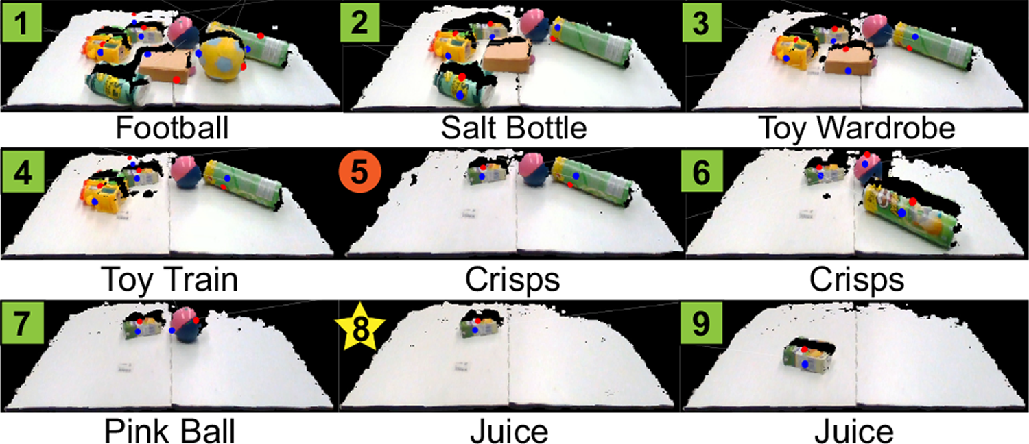
Point clouds at each step of clearing scene A: (box) successful grasp, (star, like step 8) slippery grasp, (circle, like step 5) bad contact points due to the point of view. Labels at the bottom indicate the object the robot attempted to grasp.
The same situation occurred in experiment C. However, this time the cluster made of the two mixed objects was the closest item and the robot attempted to grasp it. The result was a slippery grasp that moved the objects apart when the hand closed over the computed contact points. We have seen that this issue can be handled by our method by attempting to grasp the cluster and performing a failing grasp that does not pick up any of the objects but at least separates them. In consequence, in the following attempt, the scene is different and they may not be grouped together again. Nevertheless, the segmentation method in the proposed algorithm constitutes a module that could be changed for any other segmentation method, since the rest of the algorithm works with segmented point clouds containing the objects.
Execution times
We have calculated the amount of time required to find the best pair of contact points given the point cloud of the object, that is, the time spent on finding the grasping areas on the point cloud of an object and ranking each pair of potential contact points. We have also calculated this for point clouds with multiple objects. Table 3 presents the results obtained in terms of CPU execution time in milliseconds depending on the size of the input cloud. We additionally indicate the Root Mean Square Error (RMSE) of these times.
Execution times as regards computing a pair of contact points.

RMSE: root mean square error of the average time.
On the one hand, the biggest object in our set is the stuffed Olaf. This condition is reflected in the average amount of points contained in its recorded point clouds. It is, therefore, the object that requires the most time to be processed, reaching an average of almost 40 ms. On the other hand, the object with the smallest cloud is the mini-drill. On average, it had less than 800 points in its points clouds so processing them took an average of 9.61 ms. This object was not the smallest in dimensions, that was the juice box, but since it had a darker area around the handle, the depth camera could not record completely that part.
Generally, it takes us an average of 17.43 ms to find the best pair of grasping points given the point cloud of an object. This is clearly a fast approach as regards robotic grasping. In short, the amount of time required to process a single scene depends directly on the total number of points. The size of the point cloud simultaneously depends on the size of the objects, how close they are to the camera and the occlusions they produce.
Comparison to other methods
First of all, we compare the new version of the ranking metric introduced in this work with the one first presented by Zapata-Impata et al. 42 The changes affect the way the best grasp configuration is evaluated and the difference in the result can be seen in Figure 14. We recorded the point cloud of some objects and ran both ranking functions in order to check the difference in the computed grasp configurations under exactly the same conditions.

Difference in the computed best grasp for various objects using: (top row) the ranking function introduced by Zapata-Impata et al. 42 (bottom row) the improved version presented in this work.
With the ranking function implemented by Zapata-Impata et al., the proposed grasps are not configured completely perpendicular to the estimated axis of the object. As a result, when the gripper is executing the grasp, the object is contacted in such a way that is not stable. With the changes introduced in this work, we evaluate more appropriately the angle defined by the line that connects the grasping points and the axis of the objects. Hence, the computed grasps in our implementation are more stable because they are configured in a perpendicular orientation. See the first two objects (juice box and carton of milk) in Figure 14.
In addition, our improved version of the ranking function evaluates more correctly the curvature and the antipodal configuration of the ranked grasping configurations. See the right-most object (toy Creeper) in Figure 14. The ranking function proposed by Zapata-Impata et al. selects the same first point (blue point on the left) as us. However, the second point (red point on the right) is selected at the edge next to the edge where the first point is located. The surface on this second point is possibly less curved but the whole grasp configuration is far from being antipodal. In contrast, our improved version of the ranking function selects the second point on the opposite edge of the first point, defining a better grasp: the grasp points configure an antipodal grasp, which is more perpendicular to the estimated axis as well.
The current state-of-the-art results for robotic grasping using 3D point clouds are achieved by ten Pas et al. 39 In their work, the authors reported their performance with four approaches. Check Table 4 to find the comparison between their approach and the method we propose. The data contained in the table has been extracted from their paper. Regarding our numbers, the average grasp success reported is the average obtained in all of our experiments and the execution time is the one obtained from processing a point cloud similar in size to the ones reported by ten Pas et al.
Performance comparison of our method with current state-of-the-art results.
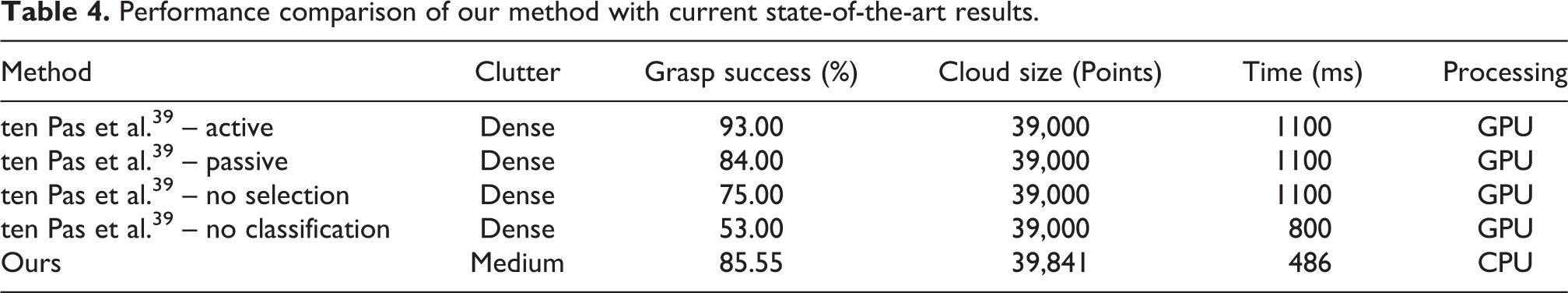
As can be seen, our method achieves the fastest results. It is remarkable that our execution times are attained using a CPU while the reported times in the work of ten Pas et al. are on a GPU. If we compare it to the Active method, the improvement in the speed calculus is of 126%, with a loss in the grasp success rate of less than 8 points. Nevertheless, the grasp success rate they report is achieved after using a point cloud obtained while moving a camera above the objects, something we do not have to do. Thus, that point cloud holds much more information about the objects’ geometry than just one single partial view.
The Passive results are obtained by using two fixed cameras, being this a closer set-up to our experiments where we used one fixed camera. The authors collected a data set of grasps using a simulator and then trained a neural network in order to learn to rank grasp poses. Using this method with a stitched point cloud from two points of views, they achieved an 84% grasp success rate. In our set-up, we do not collect nor train any model so our method does not have any prior knowledge about the objects. Despite this fact, we still achieve a higher grasp success rate, in addition to compute grasps in less than half of their time.
The fastest approach reported in their work is the No classification method. In this solution, they sampled grasp poses that were later on filtered using a set of rules so they did not make use of the trained neural network. Our method improves the grasping success rate of that approach in 61% and its time in 64%.
Despite the improvement in computation time and achieving similar grasping rates, our method is limited to medium levels of occlusion due to the segmentation method in use. In contrast, ten Past et al. work has proven to work successfully on dense clutter scenarios since their method does not need to segment the processed point cloud.
Conclusions
In this work, we describe a method for computing a pair of contact points given a single 3D point cloud with a partial view of an unknown object, available at https://github.com/yayaneath/GeoGrasp. This method analyses the cloud geometry and finds the best contact points on the basis of a set of simple geometry conditions that must be fulfilled. We propose a custom function that we use as a metric to evaluate the potential stability of the contact points computed. Our inspiration is the way in which humans usually grasp objects: by the centre of mass and perpendicular to its main axis. It is for this reason that we search for a perpendicular plane to the approximated main axis of the object and through its centroid, thus enabling potential contact points to be found near the opposite edges of this plane.
We use both these points and the axis of the object to compute a grasping pose for our Allegro robotic hand. We have followed this methodology in order to provide our robot with autonomy so that it can flexibly reach and grasp objects of diverse shapes and in distinct poses, with no need for it to have any prior knowledge of them. We have additionally built a whole system using ROS and packages like MoveIt! to simulate grasps and plan them before sending the trajectories to the real robot.
Experimentation with 27 objects and the execution of about 500 real grasps has allowed us to ascertain that the proposed method is fast and accurate. We have attained an average success rate of 85.55% in our experiments, discarding failures due to the bad point of view of the camera. On average, we compute these grasping points in 17.5 ms per object, improving the current state of the art. It is remarkable that we required only a single point cloud with a partial view of the object and no prior knowledge nor training phase in order to achieve these rates. This makes our approach useful and accessible for a wide range of environments: from robots with low computational power to industrial systems with great throughput needs.
However, our approach is highly sensitive to the point of view of the camera and the quality of the point cloud, standing this as the main limitation of the system. Point clouds can be noisy due to factors like distance or light conditions. In our experimental set-up, we were limited to work in the optimal range distance of the depth camera, so objects could not be more than 1.5 m away from it. Otherwise, the recorded point cloud could not capture properly the geometry of the object, or even the object would not be recognizable from the background. In addition, the segmentation stage is paramount for computing the best grasp configurations and the current segmentation method used is limited to scenarios which are not densely cluttered.
Although the presented experiments only work with partial views, it is still possible to process reconstructed scenes with multiple points of view, or even complete 3D objects, using our proposed method. In those cases, the grasp computation can find better grasp configurations thanks to the existence of more information about the geometry of the objects. However, the main advantage of the proposed system is that it can work with partial views from a single point cloud and find stable grasps.
We believe that there is room for improvement. In the future, we would like to enhance the segmentation stage in such a way that densely cluttered scenarios would no longer cause issues concerning two objects being confused as a single one. In addition, we would like to extend the contact points computation to find n grasping points for n-fingered robotic hands, parameterizing the algorithm to take into account the morphology of the hand and its kinematics. Moreover, we wish to explore the possibility of using tactile sensors on the fingertips, which could help us detect slips and deformations. Finally, we wish to add a human detector process to the system in order to avoid collisions with operators and collaborate with them safely.
Footnotes
Declaration of conflicting interests
The author(s) declared no potential conflicts of interest with respect to the research, authorship, and/or publication of this article.
Funding
The author(s) disclosed receipt of the following financial support for the research, authorship, and/or publication of this article: This work was funded by the Spanish Ministry of Economy, Industry and Competitiveness through the project DPI2015-68087-R (predoctoral grant BES-2016-078290) as well as the European Commission and FEDER funds through the COMMANDIA project (SOE2/P1/F0638), action supported by Interreg-V Sudoe.