
Abstract
With the advent of force control in legged robots, there is an increasing demand in research on controlling contact forces that can ensure stable interaction and balance of the system. This article aims to solve the force distribution problem by an analytic solution to regulate the contact forces particularly in a computationally efficient manner. To this end, compliance models, consisting of a virtual model of the torso and impedance models of supporting feet, are developed for a quadruped robot. The linear constraints are formulated for the analytic method based on the compliance models, and the minimization of foot slippage and the internal forces within the closed chain are also taken into account. Moreover, given the compliance models, the postural compensation of the torso can be achieved by modifying the trajectories of supporting feet in order to generate desired forces. The comparisons between the proposed analytic and numerical methods show that the analytic one is advantageous for embedded controllers due to its high computational efficiency. Finally, the effectiveness of the proposed method is first validated in simulations and then in experiments on a physical quadruped robot, and the data are presented and analyzed.
Introduction
The distinct advantages of the legged system, such as a quadruped robot, particularly has the capability of being more versatile in challenging and complex terrain compared to their wheeled counterparts. This motivates the research of designing and developing force-controlled robots that can adapt to the obstacles and pitfalls and attain stable locomotion. 1 –3
Generally, to satisfy the force–moment balance criteria for maintaining dynamic locomotion, the active force controller will apply a net wrench (force and moment) for a legged system. Nevertheless, the wrench cannot be applied directly on the torso but only through the contact forces since they are under-actuated floating-based systems. 4 Furthermore, there exists an infinite number of possible contact forces, when constraints are more than free-floating DOFs, for achieving the constraint-consistent motion. For example, a quadruped has more than two point feet supporting the torso. So to determine the mapping between the desired net wrench on the torso and the contact forces of the supporting feet is a critical part of the force distribution for this type of floating-based systems. 5 –7
Therefore, to analyze the contact forces that a legged robot can exert, there are a number of approaches to solve the problem of the contact force distribution in the literature, which can be categorized into two main classes. One is to obtain the solutions by means of numerical optimization, such as quadratic programming (QP) algorithms, 8 –11 and the other obtains analytic calculation by imposing extra constraints. The optimization-based methods determine the optimal contact forces through cost criteria and contact constraints. More specifically, the contact force distribution of the legged system is formulated as an optimal method to prevent the feet from slippage, minimizing internal force and other physical constraints. 12 Based on this, inverse dynamics is introduced to solve required torques in the joint space subject to contact constraints. 10,11
The other approach resolves the problem of contact force distribution through the analytic solution, which is beneficial for especially for embedded applications, where low-cost controllers demand effective solutions using limited amount of computation. It is characterized that the under-determined force system can be transformed into a determined one by means of imposing equality constraints. 13 By adding some extra constraints, a fully determined equation can be formulated such that leg forces can be determined by a unique solution. For instance, Trojnacki and Zielinska 14 obtain the three components of contact forces by an analytic method, and Zhang et al. 15 transforms the virtual forces into joint torques for the diagonal supporting legs by the Jacobian-transpose mapping.
In addition, due to the uncertainty of foot–ground interactions and the unknown force disturbances, the performance of legged locomotion is barely satisfactory while walking on rough terrain. In order to improve the robustness to unpredicted disturbances, compliant properties, especially the impedance modulation, is of high interest in the robotics community for the reduction of foot–ground impacts. 16,17 Thereby, researchers have successfully achieved compliant locomotion for both position- and force-controlled legged robots such as humanoids 18 –20 and quadruped robots. 21,22
The contribution of this article is the analytic solution for rapid computation of contact force distribution for legged robots, which was demonstrated effectively on a real quadruped robot EHbot (see Figure 1). Using compliance models consisting of a virtual model of torso and impedance models of feet in the Cartesian space, we are able to develop Cartesian mapping from the supporting feet to the torso and add the linear constraints for obtaining the analytic solution. A unique solution for force distribution is formulated by combining the constraints of dynamic motion equations, the foot slippage risk and the minimization of internal forces. Furthermore, in order to evaluate the performance of the proposed analytic solution used for quadruped locomotion control, real experimental results were obtained to demonstrate locomotion performance. The analytic method is benchmarked against a QP-based optimization method. In addition, the computational efficiency of the analytic method is more than twice higher than that of the numerical optimization and is hence more suitable for embedded solutions.

The quadruped robot EHbot is a force-controlled platform with 12 actuated degrees of freedom.
The remainder of this article is organized as follows. In the second section, the system modeling of the quadruped robots, that is, virtual model and impedance model in the Cartesian space, is presented. Based on these models, the third section formulates an analytic solution for distributing contact forces. Furthermore, the simulations and experiments conducted using the proposed method are further provided in the fourth section with data analysis. Finally, the conclusion and future work are given in the fifth section.
System modeling
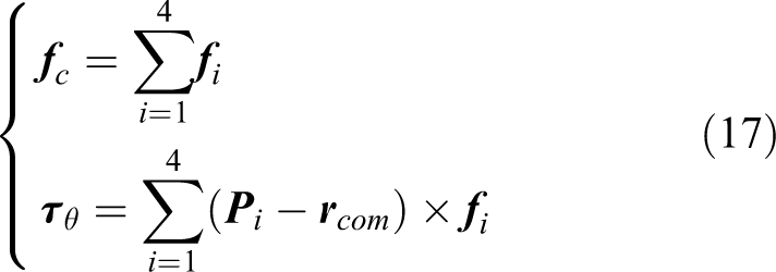
Suppose that the contact surfaces between the feet and the terrain are small enough to be considered as points, then the contact forces between them can be considered as point forces. 23 The center of mass (CoM) dynamics of a generic quadruped system is shown in Figure 2. The centroid dynamics 24 can be described as


where

The model of the generic quadruped system. The sum of contact forces on supporting feet is equivalent to the resultant force at the CoP. W represents the inertial frame, B represents the torso frame. CoP: center of pressure.
As shown in Figure 3, here a virtual model controller is applied at the torso to regulate the net wrench in the Cartesian space. 25 For the feet as end effectors, impedance control (IC) is formulated consisting of four individual impedance models in the Cartesian coordinate. Given all these Cartesian models and parameters, we can develop the mapping relationship to correlate the reflection of stiffness at the torso by the stiffness of the feet or leg. Therefore, given the stiffness at the end effectors, that is, feet, the additional contact forces can be computed by the change of reference positions to generate desired net wrench at the torso for correcting postural errors. This computation can be mathematically formulated by adding equality constraints to yield an analytic solution, which will be explained further.

Cartesian compliance models consist of a virtual model of torso and impedance models of feet in Cartesian space.
As mentioned above, the virtual net wrench is generated by the virtual model for tracking the desired locomotion. Contact forces of supporting feet are therefore required to produce appropriate virtual wrench to satisfy the force and moment equilibrium equations. According to the constraints of geometry and force, the relationship of the stiffness parameters of the torso and legs can be calculated theoretically. As shown in Figure 3, the height, pitch, and roll angles of the six-dimensional floating base (torso) play a key role in stability, compared to the motions in the forward, lateral direction and the yaw angle. Hence, the quantities of interest are the pitch and roll of the torso, and the height of the CoM described as follows


where the subscript
For simplicity, the moment components around the x and y axes generated by the virtual model are equivalent to the moment components of the impedance model on the sagittal and frontal plane, respectively. In addition, the velocity of the supporting foot is small enough such that the damping parameters have less effect on the virtual force. Thus it is reasonable for us to formulate a stiffness mapping to calculate the stiffness parameters of the virtual model. It should be noted that the stiffness mapping formulation neglects damping effects, while the virtual forces and moments produced by both the impedance model and the virtual model take damping into account. Thereby


where


Assume small angular deviations and thus constant position vectors

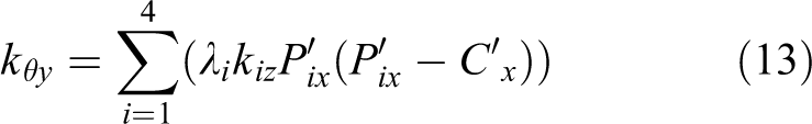
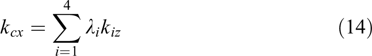
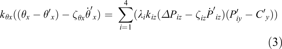
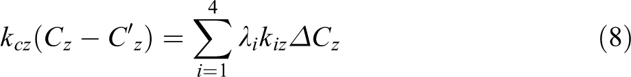
So given the impedance parameters of four feet and the corresponding coordinates, we can project the impedance of each foot into the virtual model of the torso. Furthermore, the compensation for the torsos height, pitch, and roll angles are

where
Force distribution algorithm
In the preview section, the compliance models for quadruped robots are formulated in the Cartesian space by utilizing the impedance models of feet and the virtual model of the torso. In this section, we develop a linear mapping relationship between the rotational deviation of torso and the translational displacement of each foot. Thereafter, the linear mapping can be used for the analytic solution to the problem of contact force distribution, and this can be applied in the modifications of supporting feet trajectories for compensating postural errors of the torso, which is critical to satisfy the stability based on the quadrupedal state estimator. 26
To track the desired locomotion and satisfy the force and moment equilibrium equations, the system therefore needs to apply appropriate net wrench defined by a virtual model controller for changing the linear and angular momentum. The virtual net wrench exerted on the robot can be written as

The equations of motion in equations (1) and (2) are resulted by the desired net wrench generated by a virtual model controller as in equation (16), which are in fact realized by the distribution of contact forces
where

The subscript i represents the ith contact point, that is,

where the direction cosine matrix (DCM)

where the
Equation (19) establishes the linear relations between the rotational increment of the torso and the translational increment of each foot in the Cartesian space. However, compared to the tangential forces generated by friction, the normal components are dominant due to large magnitudes. 27 Thereby, only the projection of vertical deviations is utilized

It is clearly indicated in equation (21) that there are two contributions to the displacement of foot: one is the rotation of pitch and roll angles represented by the first two terms, and the other is the translation of the torso represented by the last term. Therefore, based on the required compensation of the torso (15), the trajectories of supporting feet can be modified accordingly.
Therefore, according to the feet’s impedance models, the vertical force of the supporting foot along the z-axis direction can be calculated by three offset displacement variables

The linear equations of the displacement errors of the torso and contact forces of supporting feet are established based on the equation (21). Then these equations can be applied into the contact force distribution method for obtaining a unique solution.
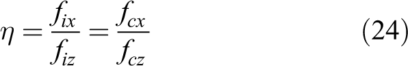
In order to avoid foot slippage, each force vector must be inside the friction cone during foot–ground interaction. We hereby define η as the radio of tangential component to the normal component of the ground reaction force (GRF). Thus,
To prevent slippage by minimum norms of distributed forces, setting all the radios the GRFs

Generally, terrestrial mammal and quadruped robot walk mostly in sagittal direction with minimized sideway movements, so the tractive forces are mainly along the forward direction of quadruped system.
15
In order to obtain an analytic solution for the latter derivation, the ratio η can be simplified by assuming negligible lateral tractive forces as zero
Hence, we have
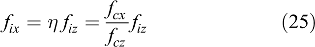
Once
The above formulation of analytically solving the contact forces considers the proportional relation of the force component by reinforcing η. However, to prevent foot slippage in case of centroidal forces
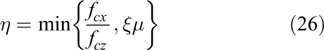
Note that this constraint is a linearized Coulomb friction cone represented by an outer approximation in a pyramid shape instead of the circular one.
From the above formulations which introduce six constraints and combining the Newton–Euler dynamics (17), we can obtain seven equations with seven unknowns, where the linear equation in the form of
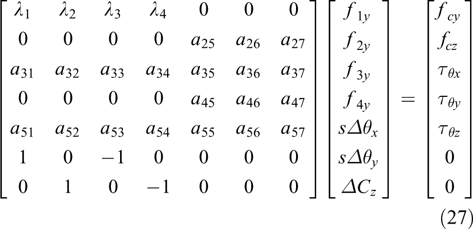
All the elements in coefficient matrix
The equation (27) has a solution if and only if

More generally, the equation (27) can be solved by using pseudo inverse as

With the solution from equation (28) or (29) will be used for computing the feedforward and feedback terms, respectively. The solution of
The contact forces in
All these four contact forces are used for the feedback control of the translational and rotational motion, which are realized via the joint torque control as

Simulation and experimental results
In order to validate the proposed method of contact force distribution, we demonstrate a series of tests in simulations and then on a quadruped prototype, EHbot. First, a set of random virtual net wrench in Table 1 are used to calculate and analyze the results of contact forces using the proposed analytic solution in simulation.
Range of magnitude of random net wrenches.

Based on Table 1, 10,000 random net wrenches are generated to simulate the centroidal forces and torques computed by the virtual model. Under the normal standing situation, the information of EHbot, such as position and impedance parameters, is used for obtaining the coefficient matrix

The normal forces versus the absolute tangential forces: (a) without friction constraint; and (b) with the friction constraint for anti-slippage. The blue line represent the boundary of the friction cone with a conservative friction coefficient
As illustrated in Figure 4(b), the implementation of friction constraints can effectively avoid foot slippage with the possibility of slipping risk reduced from 6.47% to 0.04% (with ξ = 0.95) despite the existence of poorly defined virtual wrenches. More importantly, using the friction constraints, the infeasible wrench input in certain circumstances (e.g. high acceleration) can be effectively resolved for satisfying the physical viability. In turn, the introduction of the anti-slip factor ξ as a safety margin also limits the viability range of the quadruped locomotion, which can be a disadvantage. Nevertheless, for static walking gait of quadruped robots at low speed, that is, the system is over-actuated with three or four feet on the ground, the anti-slip factor ξ can meet the requirements of the flexibility of the quadruped locomotion.
We implemented the proposed algorithm of contact force distribution on the EHbot quadruped. EHbot, an electro-hydraulic quadruped prototype, is the latest version in the lab. It has a variety of sensors developed to explore and analyze the balance control of legged system. More information about the experimental system can be found in Shi et al. 29 The trajectories of supporting feet were modified using equation (21) for the compensation of torsos posture. To validate the effectiveness, we first carried out a series of experiments of static motion, with the front legs standing on a box using three different controller: (a) IC, only the impedance models of supporting feet were applied without the proposed force distribution to adjust the torsos posture; (b) the proposed force distribution (Force_Dist.) & IC, in which the analytic solution of the contact force distribution was applied with the virtual model control and leg impedance models; (c) feedforward compensation of modify foot trajectories (ModifyTraj.) & Force_Dist. & IC, in which the steady error of torsos posture was reduced by modifying the trajectories of supporting feet.
Figure 5 shows the results of the average normal forces of the front and hind legs in each experiment. The results demonstrate that the larger force errors of the front and hind legs exist while using only the IC. Despite using the contact force distribution will generate net moment to reduce the postural error of the torso, this feedback control term a priori requires the non-zero postural error in order to compute a control effort. Hence, feedforward compensation is needed such as modifying the supporting feet trajectories in accordance with the Cartesian compliance models. Note that the difference of normal forces of the front and hind legs is mainly caused by asymmetric distribution of the mass. As shown in Figure 5, large angular errors can be minimized by the feedback control using distributed contact forces, and the trajectory modification of the supporting feet can further reduce the postural errors to zero, which also suggests that the assumption of our formulation of small angular errors, that is, equations (9) and (10), is reasonable.

Experimental results of the mean normal forces of the front and hind legs while the front legs standing on a box at a height of 150 mm. Three experiments were carried out with different controls (a) Cartesian impedance control only; (b) proposed force distribution and Cartesian impedance control; and (c) modified trajectories and proposed force distribution and Cartesian impedance control. The lower graph show the snapshots of the posture of the robot in each experiment.
The second validation is the simulation of quadruped walking on rough terrain (see Figure 6) with 0.2 m/s. The test was carried out in the Gazebo 7 simulator. As shown in Figure 7, the yellow shaded area represents the duration of terrain disturbance. Figure 7(a) shows that the maximum amplitudes of pitch and roll angles are less than 3.0° and 6.0°. Figure 7(b) shows that the postural angles can restore to the desired ones in presence of large terrain variations during 24 s and 28 s. Besides, it was found that when the FL foot steps on a high plank (at 24.2 s), the large errors between the desired and actual normal forces cause the system to be unstable. Once the controller reduces the residuals close to zero, the corresponding posture is then stable again during 27 s and 28 s.

Snapshots of the simulation of quadruped walking on rough terrain.

Simulation results of quadruped walking on rough terrain with proposed controller. Upper graph is the pitch (red line) and roll (blue line) angle of the torso with maximum amplitude less than 3.0° and 6.0°, respectively. The yellow shaded area represents the duration of terrain disturbance. Lower graph presents the leg contact patterns with stride duration of 2.0 s and the normal force of the FL (left-front) leg during large terrain disturbances. Bar patterns indicate the stance phase. Red line indicates the distributed normal force. Blue line is the actual normal force.
In the third validation, in order to compare the performance of the proposed analytic solution with an optimal solution in equation (12), we applied both methods to the robot walking in place, in both the simulation and the experiments, under the same circumstances (terrain, computer, etc.). Note that all the above algorithms are implemented on a personal computer with 2.3 GHz quad-core Intel Core i5-6300HQ processor. The qpOASES-3.2.0 library 30 is used for optimal method. And ROS Indigo and Gazebo-7 on Ubuntu Linux are used to build the simulation platform. Figure 8 shows the experimental results of comparing the torso’s roll angles from both methods. We see that the maximum roll angle amplitude with the analytic method is no more than 5.5°, which is slightly bigger than the maximum angle amplitude (approximately 4.0°) with optimal method. The phenomena of angle amplitude’s asymmetry may be caused by the uneven distribution of mass.

The comparison of the roll angles of a quadruped physical quadruped prototype EHbot solved via the analytic and optimal method. The maximum roll angle amplitude with the analytic solution (red line) is no more than 5.5°. While the maximum roll angle amplitude with the optimal method (blue line) is about 4.0°.
It should be emphasized that the analytic solution is more computationally efficient and can provide more computing resources for other algorithms. Compared to the average computation of the optimal solution of 0.16 ms, our analytic approach has an average of 0.07 ms only, which is less half the time. Similar results have been discovered in different computers. As can be seen in Figure 9, the snapshots of conducted experiments show that the proposed method was successfully implemented on a quadruped platform EHbot. These tests demonstrated the effectiveness of the proposed method for contact force distribution.

Snapshots of the experiment of walking in place on a quadruped robot EHbot.
Conclusion
This article proposed an analytic solution for solving the problem of contact force distribution considering friction constraints for stable quadruped locomotion. Using impedance models in the Cartesian space for the control of legs and virtual model control of the torso, we are able to develop linear relationship between the postural errors and the corresponding increment of foot trajectories for the feedforward compensation. Hence, posture errors of torso can be compensated by modifying the trajectories of supporting feet. Then by combining with the Newton–Euler dynamics, the internal forces can be minimized by using the tangential-normal ratio η, which is used for the friction constraints to prevent foot slippage. All this can be formulated analytically, and thus the solution of force distribution can be computed with high computational efficiency for the implementation on low cost controllers. This allows a wider range of applications in which real-time computation is critical.
However, there are some limitations in this analytic method. One of the assumption is that the lateral tractive force is close to zero, so this control method is vulnerable to large lateral disturbances. In addition, as a trade-off, the performance of this algorithm is less desirable than that of the optimal method, therefore it is suitable for low-cost controller for reducing the computation. In the future, we would like to reformulate the problem to achieve better performance in terms of accuracy of the solutions at high computational efficiency.
Footnotes
Declaration of conflicting interests
The author(s) declared no potential conflicts of interest with respect to the research, authorship, and/or publication of this article.
Funding
The author(s) disclosed receipt of the following financial support for the research, authorship, and/or publication of this article: This work was supported by National Nature Science Foundation of China under Grant No. 61473015, 61773139, and U1713222, the Shenzhen special fund for future industrial development JCYJ20160425150757025 and Shenzhen Peacock Plan KQTD2016112515134654.
Supplemental material
Supplemental material for this article is available online.
Appendix 1
Some elements of coefficient matrix
The determinant of the coefficient matrix is
References
Supplementary Material
Please find the following supplemental material available below.
For Open Access articles published under a Creative Commons License, all supplemental material carries the same license as the article it is associated with.
For non-Open Access articles published, all supplemental material carries a non-exclusive license, and permission requests for re-use of supplemental material or any part of supplemental material shall be sent directly to the copyright owner as specified in the copyright notice associated with the article.