
Abstract
In the article, a heavy-duty quadruped robot was designed. A parallel cylinder transmission scheme for the heavy load torque of the hip joint of heavy-duty hydraulic quadruped robot is proposed, the mathematical model of the parallel cylinder system is derived, the model characteristics of the parallel cylinder system are analyzed, the characteristics of internal force and joint control of parallel cylinders are considered, the force/position hybrid control of parallel cylinder is proposed to eliminate the internal forces and realize the requirement of joint control and the force/position control is decoupled by the design of the force and position signal. According to the characteristics of the servo cylinder force control model, the flow compensation and speed compensation are introduced, the minimum control synthesis controller is used to control the servo cylinder force and the proportional integral controller is applied to control the position of servo cylinder. The compound control strategy is analyzed on the table of parallel cylinder, and the experimental results show that the amplitude attenuation and phase lag of position and force are less than 10% and 18°, respectively, and the efficiency of the proposed control strategy is verified. The research results of this article will be widely used in many fields of robot control in the future.
Keywords
Introduction
Most electro-hydraulic servo actuators have been used as driving units of hydraulic quadruped robot, which have the characteristics of large driving force, high power density and compact structure. Since 2005, Boston Power Company has announced the research and development of hydraulic quadruped robots such as BigDog, LS3, Wildcat, SPOT and so on, the excellent dynamic performances of the hydraulic quadruped robots have attracted wide attention immediately. 1,2
Under the influence of this background, the research work of hydraulic quadruped robot has been carried out in many countries. The hydraulic quadruped, HyQ (as shown in Figure 1) MiniHyQ and HyQ2MAX have successively developed a multipurpose robot system with hydraulic transmission actuation by the Department of Advanced Robotics of the Istituto Italiano di Tecnologia (IIT). 3 Korea Institute of Science and Technology has also launched a quadruped robot called Jinpoong. 4 Hydraulic quadruped robots have been studied in Shandong University, Beijing Institute of Technology, Harbin University of Technology and National Defense University of Science and Technology. 5 –7

Physical diagram of hydraulic quadruped robot HyQ of Istituto Italiano di Tecnologia. (a) Images for 2012, no stereo cameras installed. (b) Images for 2012, stereo camera mounted on a particular device.
The robots mentioned in this article except for the LS3, the hip joints of all above-mentioned quadruped robots are driven by a single actuator. The difference is that HyQ uses a single motor and other robots use a single electro-hydraulic servo actuator. A double actuator cylinder transmission scheme is presented for this study, the LS3 robot has a payload of up to 181 kg. And also because there are the special backgrounds of Boston dynamics, the technical data on LS3 robots have been less reported. 8
Hydraulic quadruped motion has always been an active field of robot research at present. Up to now, few studies have been made to integrate force/position hydraulic control of a parallel cylinder transmission system on quadruped platforms. 9 For the development of hydraulic quadruped robots, hip joint motion is an extremely complicated process of the robot, which involves different components from four symmetrical legs, four rotating joints and each leg hydraulic actuator to a hinged torso equipped with computers, controllers and sensors. 10 –12
Due to the larger distance between the robots’ foot and roll shaft, in the same foot end force, the required driving torque is larger. 13 –15 In order to obtain the required driving torque, it can be realized by increasing the oil supply pressure, increasing the effective area of the hydraulic cylinder and adopting multi-cylinder parallel connection and other ways. The limitation of hydraulic components makes the oil supply pressure of hydraulic system cannot be infinitely increased. Although the method of increasing the effective area of the hydraulic cylinder can increase the torque, it cannot be designed too bigger for the structure limitation (there is not enough running space for larger cylinder, as shown in the green and red circles in Figure 4), which further limits the exchange range of the electro-hydraulic servo actuator and increases the processing cost. Therefore, in view of the above-mentioned factors, multi-cylinder parallel is an ideal choice to achieve large torque output of the robot.
In this article, according to the larger load torque of hip joint of heavy-duty hydraulic quadruped robot, the parallel cylinder drive model was analyzed, considering the characteristics of position control and driving force control of roll joint, the mathematical model of parallel cylinder system was derived and the decoupling algorithm force/position hybrid control of parallel cylinder was constructed by analyzing the characteristics of model. Considering the model characteristics of force control of electro-hydraulic servo actuator, the minimal control synthesis controller was designed, and the driving force control was realized. The algorithm of force/position hybrid control was verified on semi physical system of cylinder parallel, and the efficiency of the proposed control strategy was verified.
Control parameters analysis and kinematics model of mechanical system
Analysis of double cylinder driving form
The joint description of the hydraulic drive robot is shown in Figure 2. For the parallel actuator, A, B and C are the connecting points of bottom of the hydraulic cylinder, the joint shaft and the piston rod, respectively, C′ is the position of the hydraulic cylinder when it is fully extended. From the diagram, the cylinder bottom of another hydraulic cylinder A′ cannot be located in the sector area composed of CBC′ and DBE when the driving mode is double cylinder. At this point, the drives joint of piston rod have a dead center, and the desired motion cannot be achieved.

Principle diagram of parallel actuator.
According to the above-mentioned analysis, the bottom end of another hydraulic cylinder can be arranged in the sector area composed of CBD and C′BE. When A′ is arranged in the area C′BE, its structure is shown in Figure 3. In the form of figures (a) and (b), these methods are easy to cause the movement interference of the robot leg structure in the inside and outside pendulum. And the form (b) will increase the overall width of the robot.
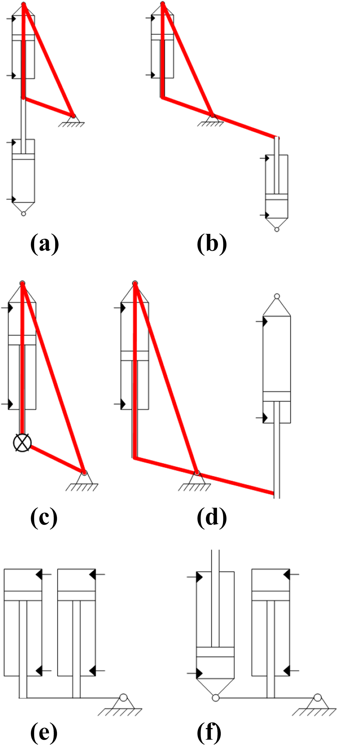
Types of parallel cylinder.
When A′ is arranged in the CBD region, its structure is shown in Figure 3. If using the form of figure (d), the two hydraulic cylinders are located on both sides of the joint shaft. Because the rotation of the roll joint is more than 45°, and the joint contains a hydraulic cylinder. In order to achieve the desired joint rotation angle, it is necessary to increase the length of the arm of force, which does not meet the requirements of compact structure. In figure (c), two hydraulic cylinders are located on the same side of the joint, avoiding the problem of figure (d), for this purpose, this article uses the form shown in figure (c).
For figure (c), there are two kinds of arrangement of two hydraulic cylinders. In figure (e), the driving force of roll joint in the positive and negative directions are different. The form of figure (f) can guarantee the same driving force of roll joint in the positive and negative directions, and it is an ideal choice. However, due to the change of link form, it is difficult to exchange actuator. Namely, figure (e) shows the best choice.
Electro-hydraulic servo actuator modelling
The three-dimensional model of hydraulic quadruped robot driven by parallel cylinder system is shown in Figure 4. The quadruped robot has 12 active degrees of freedom (DOFs) and 4 passive DOFs. The whole machine consists of 16 electro-hydraulic servo actuators of the same type. The four roll joints are driven by two electro-hydraulic servo actuators to increase the joint drive torque.

Three-dimensional model of hydraulic quadruped robot. (a) Model of hydraulic quadruped robot and (b) single leg model of quadruped robot.
In order to obtain the equivalent model of electro-hydraulic servo actuator, the following assumptions are made: (1) The moment of inertia of leg mechanism rotate around roll shaft is JL; (2) the torque of force to roll shaft is TL; and (3) the equivalent stiffness of damping spring to roll shaft is

Diagram of parallel cylinder system.
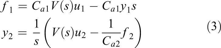
Figure 5 shows that roll shaft actuator is a typical redundant drive system. In the position control mode, because the two actuators do not operate synchronously, a larger internal force will be generated and reduce the effective driving torque of the roll actuator. In order to avoid movement interference, the position of actuator should be taken into account in the driving force control mode. According to the works of Wang et al., 16 Shao et al., 17 Gong et al. 18 and Zhang et al., 19 the transfer function of single cylinder electro-hydraulic position servo system can be obtained, as shown in the following equation

where A
p is the effective area of piston of servo cylinder, Ka is the gain of servo amplifier, Ksv
is the flow gain of servo valve, ω0 is the composite natural frequency, ζ0 is the comprehensive damping ratio, Kh
is the hydraulic spring stiffness, K is the load spring stiffness,
Double cylinder motion analysis
Due to the actuator installation error, the installation and measurement error of the displacement sensor, the dynamic performance difference of the actuator and the synchronization of the actuator motion cannot be guaranteed. And the actuator and robot joints are rigid contact, and the smaller displacement deviation of actuator will produce greater internal force, thereby reducing the effective output force of actuator. The position control and the driving force control of the two actuators are carried out, which is, the force/position hybrid control of the roll joint is realized indirectly. Not only the required driving torque is obtained but also the position of robot joint is ensured.
The formula (1) shows that for the position control, hydraulic cylinder external disturbance force f is the output of hydraulic cylinder of force control. That is, there is a coupling between the output of position control cylinder and the output of force control cylinder. The output of the system influences each other, which reduces the precision of the position servo and the drive force servo. If decoupling is achieved, the desired force/position control accuracy can be obtained.
The decouple of force/position hybrid control
Due to the coupling of force/position hybrid control hydraulic cylinder, the direct input of each signal command will affect the servo accuracy of hydraulic cylinder. If the input signal is properly selected and the decoupling of the two hydraulic cylinders is realized, the mutual influence between the two hydraulic cylinders can be eliminated so as to improve the control quality of the system.
If


Equation (1) can be rewritten as

Equation (2) can be expressed as equation (3) for cylinders 1 and 2
The relationship between displacement and force of the parallel cylinder system can be described as


The matrix form of equation (3) is shown as follows

Equation (6) can be rewritten as

Equation (7) can be rewritten as

Equation (8) can be rewritten as

If

Thus

The decoupling of the input signal is realized by formula (11). In the actual system, the input signal can be written as
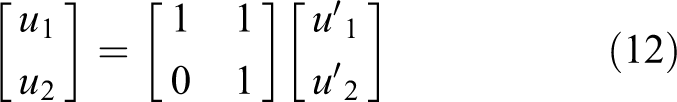
Equation (12) can be rewritten as

Usually, only smaller control signal is needed to obtain the required driving force, so

According to equation (14), the decoupling of the input signal is realized by the double cylinder parallel system, so that the position control cylinder and force control cylinder have no influence on each other. The diagram of parallel cylinder system of force/position control is obtained, as shown in Figure 6.

Diagram of parallel cylinder of force/position control.
Kinematics and dynamics analysis of quadruped robot
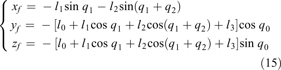
The hydraulic quadruped robot dimension is shown in Figure 7, where l0, l1, l2 and l3 are the length of the corresponding link; q0, q1 and q2 are the joint angle of the corresponding link;

Dimension of hydraulic quadruped robot leg.
Kinematics equation of robot
As shown in Figure 7, the foot end equation is described as follows
From equation (16), the relationship between roll actuator displacement and joint angle of hip joint can be described as

Because of the structure limitation, foot end coordinate value
Equation (16) coordinates value xf and yf can be rewritten as

The value of


Equation (17) can be rewritten as

The value of


Because of the structure limitation of hydraulic quadruped robot, then
Dynamic equations of robot
The kinetic energy and potential energy of robot can be obtained from Figure 7, on this basis, the system dynamic equation (23) can be obtained according to the Lagrange equation
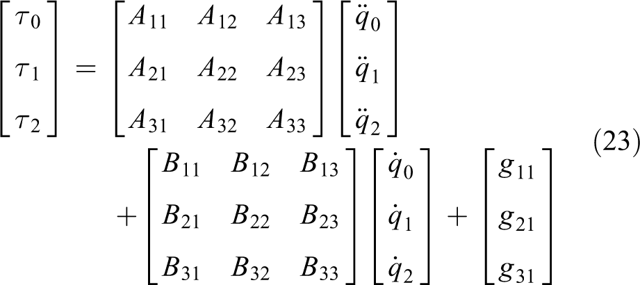
where

Thus, the desired trajectory can be planned by kinematics equation, and the needed joint torque can be obtained by the dynamic equation.
In this study, the joint motion of a hydraulic quadruped robot is driven by a hydraulic cylinder mounted on the legs of the robot. Therefore, it must be based on the length of the leg of the hydraulic quadruped robot designed and the installation position of the hydraulic cylinder in the leg. In order to describe the output decouple of force/position hybrid control of robot, thus the output decouple of force/position hybrid control in the AMESim. The characteristic of decouple of force/position hybrid control system is analyzed by drawing the curve time-domain analysis diagram of the desired location and the physical location by AMEsim. Time-domain curve of decouple of force/position hybrid control system slope response is shown in Figure 8. Time-domain curve of decouple of force/position hybrid control system step response is shown in Figure 9.

Time-domain curve of decouple of force/position hybrid control system slope response.
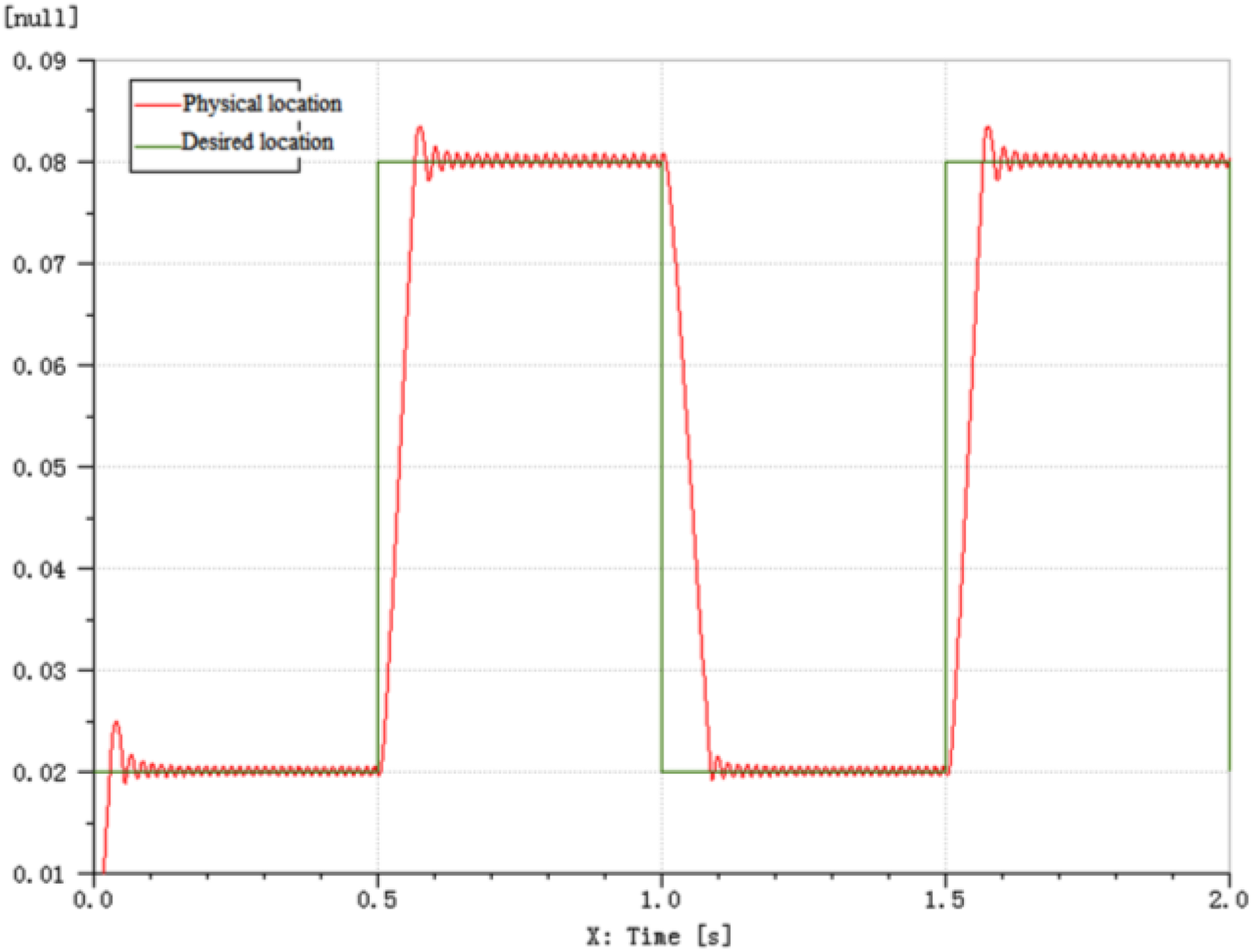
Time-domain curve of decouple of force/position hybrid control system step response.
Controller design
The proportional integral controller is adopted in the position control, and the composite strategy with flow compensation, velocity compensation and minimal control synthesis is adopted in the force control, which is illustrated in the work of Ba et al. 20
Experiment study
The composite strategy can effectively reduce the inner force and improve the effective driving force; it is verified on the table of parallel cylinder system. The electro-hydraulic servo actuator of quadruped robot is shown in Figure 10. During the experiment process, the supply pressure is 7.0 MPa, the sensor signal quality is improved by using low-pass filter with 250 rad/s cut-off frequency.
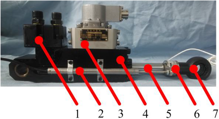
Electro-hydraulic servo actuator of quadruped robot. 1. Valve block. 2. Displacement sensor. 3. Asymmetric servo valve. 4. Hydraulic cylinder. 5. Position rod. 6. Force sensor. 7. Joint bearing.
Experiment of position control
Based on the diagonal trotting state, the two legs of the quadruped robot on the diagonal line are completely identical in motion and are in the same phase or in the supporting phase. This kind of gait has low energy consumption, fast speed and relatively stable walking. The hip joint position response curve is shown in Figure 11. For this article, the parallel cylinder system is zero bound damping, and the steady-state error and asymmetry of velocity are shown as asymmetric amplitude attenuation and phase hysteresis.

Comparison of actual and expected position response curves of hip joint.
The displacement response curves of 1.0-, 1.5- and 2.0-Hz systems are shown in Figure 12. Curve 1 is the command signal, and curves 2 and 3 are the corresponding position response curve of cylinders 1 and 2, respectively.

Position curve. Response curve of (a) 1.0 Hz, (b) 1.5 Hz and (c) 2.0 Hz.
The force response curves of 1.0-, 1.5- and 2.0-Hz systems are shown in Figure 13. Curves 1 and 2 are the corresponding force curve of cylinders 1 and 2, respectively.

Force curve. Response curve of (a) 1.0 Hz, (b) 1.5 Hz and (c) 2.0 Hz.
As shown in Figure 12, curves 2 and 3 have the similar response characteristics.
As shown in Figure 13, curves 1 and 2 have different performance with the same position response characteristics. Curve 2 is always negative, curve 1 is changed in positive and negative, and it reduces the output force of actuator when its value is positive.
Experiment of internal force inhibit
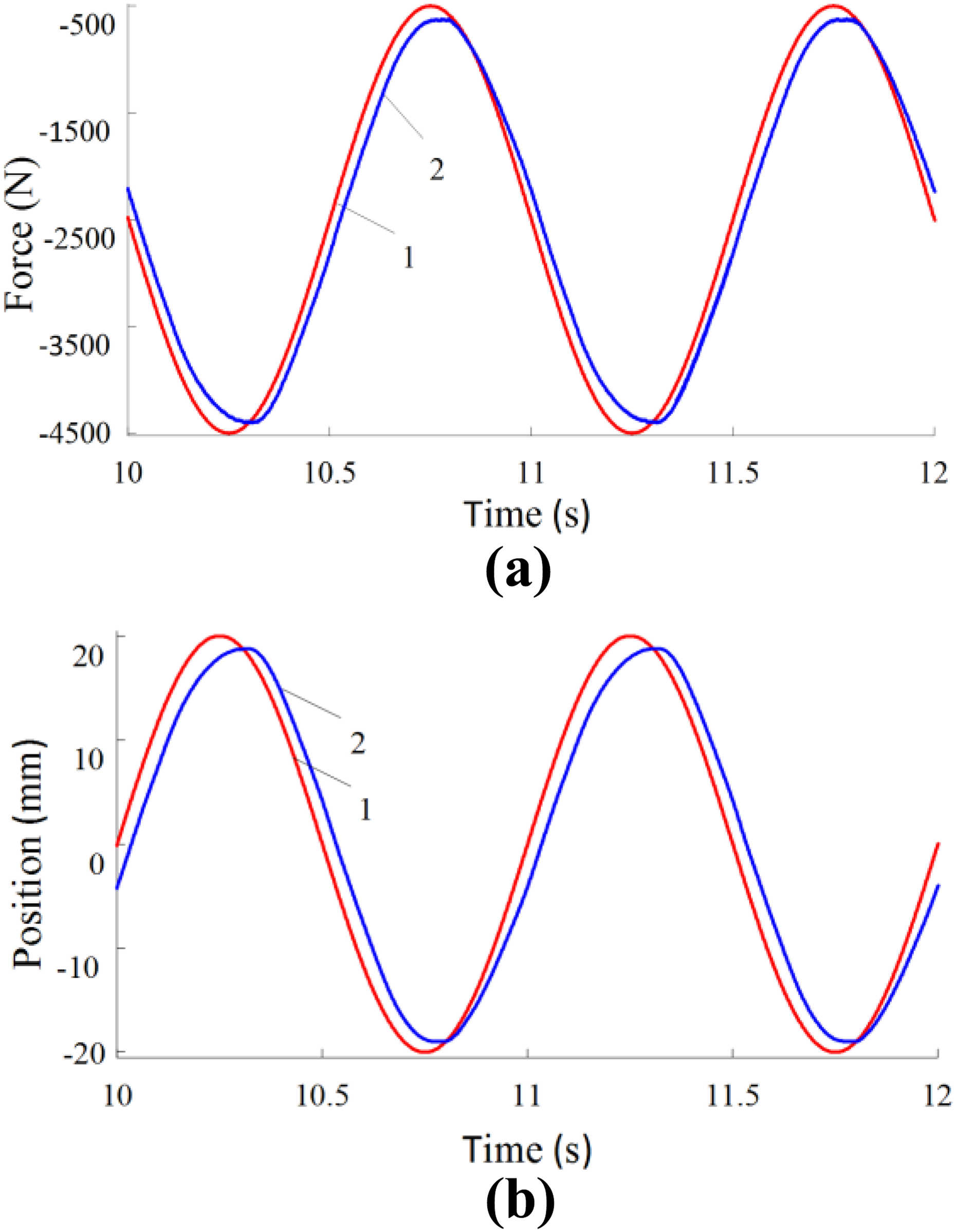
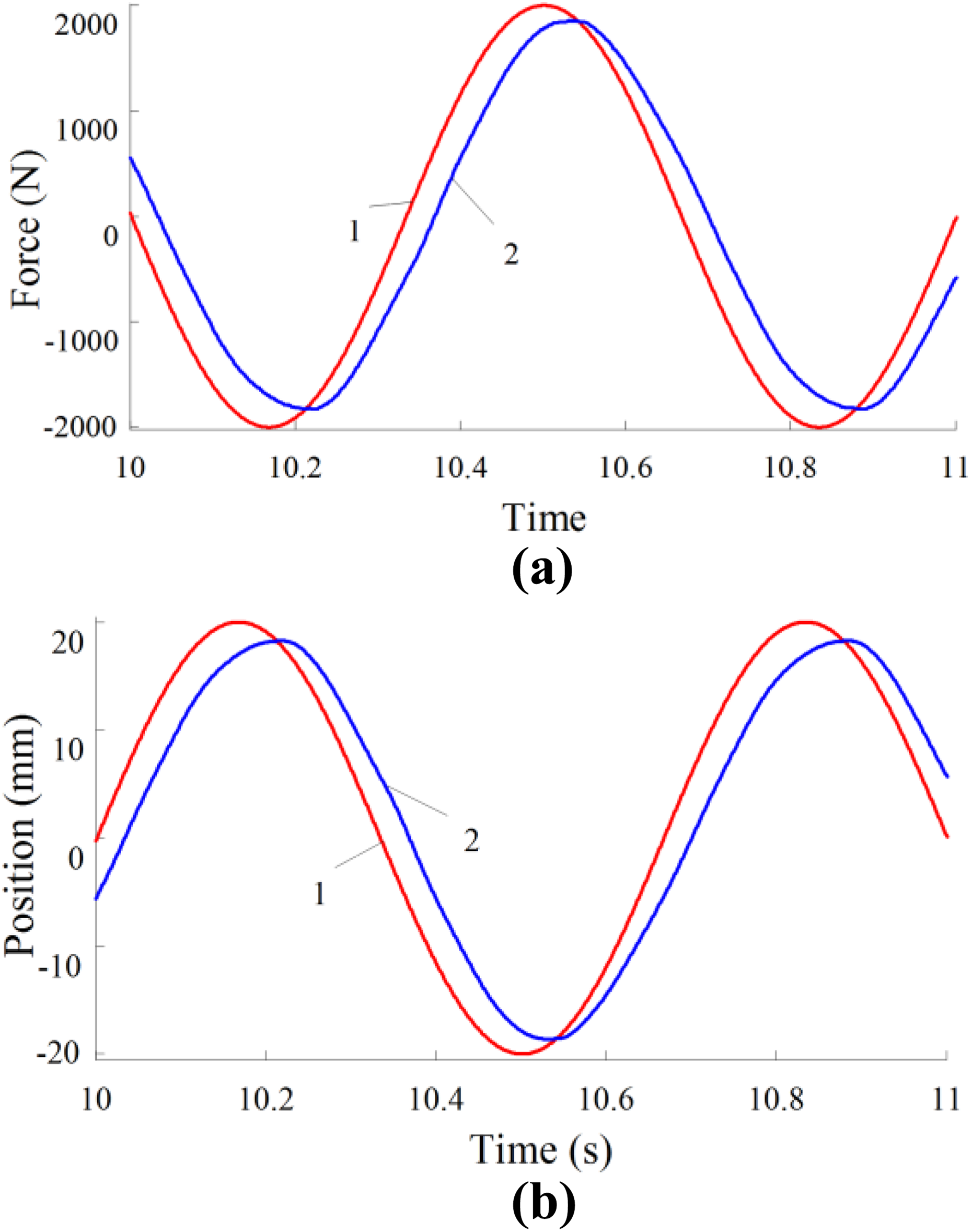
The displacement and force response curves of 1.0-, 1.5- and 2.0-Hz systems are shown in Figures 14 to 16. Figures 14(a), 15(a) and 16(a) show the driving force response curve of servo cylinder, the signal amplitude is 2000 N. And Figures 14(b), 15(b) and 16(b) show the displacement response curve of servo cylinder, and the signal amplitude is 20 mm. Curve 1 is the command signal, and curve 2 is the corresponding response curve.
Response curve of 1.0 Hz. (a) Driving force curve and (b) position curve.
Response curve of 1.5 Hz. (a) Driving force curve and (b) position curve.

Response curve of 2.0 Hz. (a) Driving force curve and (b) position curve.
It is shown that the double cylinder parallel system has good tracking performance under given signal. The amplitude attenuation and phase lag of position tracking signal and force tracking signal are close to each other. When the command signals are 1.0, 1.5 and 2.0 Hz, the amplitude attenuation is 5%, 7.5% and 8%, respectively, and the phase lag is 9°, 13° and 18°, respectively. The effectiveness of the force/position hybrid control of parallel cylinder is proved. With the increase of excitation signal frequency, both amplitude attenuation and phase lag of the system are increasing. In engineering, phase lag can be compensated by feedforward controller.
Conclusions
In this article, a scheme for heavy-duty quadruped robot to analyze motion and force/position hydraulic control of a parallel cylinder transmission system was proposed.
According to the larger load torque of hip joint of heavy-duty hydraulic quadruped robot, the parallel cylinder drive was proposed to improve the driving torque.
According to the characteristics of parallel cylinder system, the decouple of force/position control was realized by designing the force signal and position signal.
The composite strategy was verified on the table of parallel cylinder system, and the experimental results show that the force control and position control were have good dynamic response, and the efficiency of the proposed control strategy was verified.
The research results of this article will be widely used in many fields of robot control in the future, such as hoisting operation, machining, remote sensing control and so on.
In the following research, various optimization conditions are also applied to the inverse solution of the contact force or control torque of the multi-DOFs robot. The stability of the system is being analyzed and results will be added to the next study.
Footnotes
Acknowledgement
The authors gratefully acknowledge the Harbin Institute of Technology (HIT) as well as the Harbin University of Science and Technology (HUST) for their support.
Declaration of conflicting interests
The author(s) declared no potential conflicts of interest with respect to the research, authorship, and/or publication of this article.
Funding
The author(s) received no financial support for the research, authorship, and/or publication of this article.