
Abstract
Fishes can avoid colliding with obstacles and track baits depending on the lateral distributed sense nodes which can sense the pressure variances of the surrounding flow field. Fish often uses the lateral-line system as their only means for navigation, especially under poor visual conditions. This sensing mechanism provides a new perspective for researchers and engineers to build such a sensing system that could be applied to control and near field navigation for underwater robots and vehicles. In this article, a pressure-sensing-based is proposed, with 10 pressure sensors acting as lateral line and use the three-dimensional printer to print the fish structure and install the artificial lateral line on it. Through preliminary experiments and numerical simulation, we obtain the pressure sensor data. By comparing the experimental data with the numerical simulation data, it can be verified that the pressure variation of the pressure sensor in the numerical simulation data is consistent with that in the experimental data. The artificial lateral line provides a new sense to man-made underwater vehicles and marine robots, so that they can sense like fish.
Introduction
As the scope of human activities becomes more and more extensive, it is necessary to guarantee the supply of all kinds of energy, which results in the present situation of the shortage of resources. The ocean covers 70.8% of the earth’s surface, which provides rich mineral resources, marine resources, oil, and natural gas. Early humans make use of marine resources by fishing or other tools. 1 With the advanced civilization, mankind became aware of the importance of the sea to human development. In fact, human utilization of marine resources is very limited due to the complexity of the marine environment and the lack of light in the seafloor. For this reason, people are developing all kinds of sophisticated instruments and sensing detection devices such as snake robot 2,3 to assist mankind in the further exploration.
Fish in the darkness of the water environment can show excellent ability in swimming, this completely because the fish has incomparable perception system. 4 The flow of the surrounding water environment provides important environmental information. Found in most fish and some other aquatic organisms, the lateral line is a common mechanosensory system that serves an important role in various behaviors including station holding, rheotaxis (the ability to orient parallel to a flow field), schooling, prey detection and capture, and social communication. 5 The neuromast, a mechanoreceptive structure, is believed to be responsible for the functionality of the lateral line. Specifically, as illustrated in Figure 1, superficial neuromasts located on the body surface and protruding into the external fluid respond to steady and low-frequency components in the flow in proportion to the net velocity. Canal neuromasts situated in subdermal canals along the lateral lines respond to high-frequency components and react proportionally to the net acceleration (or the pressure gradient). 6 In effect, by detecting water motions and pressure gradients in the surrounding environment, the lateral line system provides hydrodynamic information that in turn facilitates many behavioral decisions.
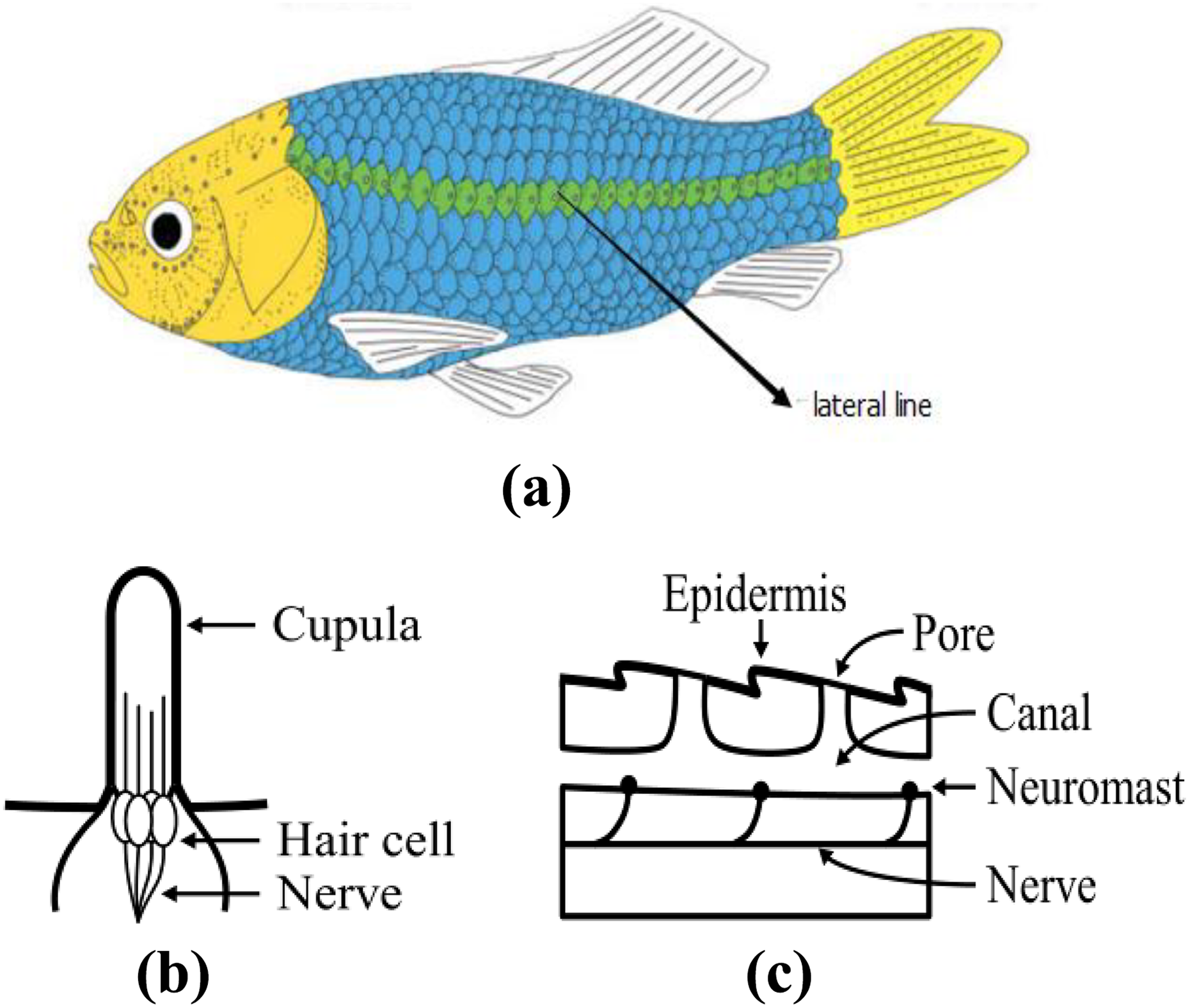
(a) Schematic of a typical layout of the lateral line in a fish. (b) Schematic of the superficial neuromasts that are located on body surface and respond to low-frequency components and net velocity. (c) Schematic of the canal neuromasts that are inside subdermal canals and respond to high-frequency components and net acceleration of the flow.
In order to cope with different complex environments, underwater robots have begun to equip different sensing systems. At present, the sensing ability of underwater vehicle mainly rely on ultrasonic and visual image processing method. 7 However, the underwater environment is complex, the water wave noise is seriously disturbed, and the optical environment such as refraction and lack of illumination can cause very strong interference to the existing sensing system of underwater robot. 8 It is an urgent problem to overcome these reasons, to make the underwater robot perceive the surrounding environment and to complete complex task more accurately.
Researchers hope that underwater robots can make full use of surrounding water environment information. Usually, the underwater vehicle senses the flow information through the Doppler analyzer. 9 The Doppler analyzer can measure the global flow rate, and its value will be used to compensate for the drift in the navigation system. Compared with the lateral-line system of fish, Doppler analyzer cannot detect local flow. 10 At the same time, the Doppler analyzer is quite expensive and the bulky instrument still needs a lot of energy. Therefore, the Doppler analyzer is not suitable for small underwater vehicle. 11
Therefore, the research of artificial lateral-line system design and its sensing ability has great value in scientific research and practical application. The artificial lateral-line system can enable the underwater robot to locate and perceive the location of the obstacles and ensure that the underwater robot can make effective obstacle avoidance and path planning. 12 At the same time, the underwater vehicle can not only sense the change information of water environment caused by external events but also can get information about changes in the water environment caused by their own motion in vast waters. 8 The original intention of designing the artificial lateral-line system is to give the underwater robot the ability to perceive the fluid change in the surrounding water. The artificial lateral line is a method to sense complex environment, which is different from the previous engineering methods, and to improve the sensitivity of underwater vehicle motion perception in the water environment. It provides more precise perceptual conditions and control information for underwater obstacle avoidance and its own path planning, which makes the underwater robot achieve accurate position and pose control in water.
In the past few years, many kinds of flow sensors and sensor arrays were fabricated by mimicking the superficial lateral line. 13 Different materials, such as IPMC, were used and different structures were designed such as cantilever beam. 6,14,15 Probes were proposed as an alternative to measure the external flow velocity and direction. Localizing and identifying a cylinder with square and circular cross sections in still and running water were also investigated. 16 Most researches on lateral-line applications focused on the fluid flow properties instead of pressure information. 17 On the other hand, the canal lateral line can respond to hydrodynamic stimuli even in the presence of unidirectional water flow, whereas superficial lateral line, which predominate in still-water fish, cannot. 18 Even the lateral-line system consists of both superficial and canal lateral lines, it is unnecessary to build a sensing system completely the same as biological lateral line. 19 Therefore, our work focuses on the pressure information in the local field.
In this article, we use three-dimensional (3-D) printer to print the simple fish-shaped structure and select 10 pressure sensors which meet the experimental standard as the sensing units of the artificial lateral-line system and design the outer surface and the joint of the artificial lateral-line system.
Prototype and experimental device
In view of the characteristics of high efficiency, high speed, and low noise when tuna swims in the water, we designed the underwater robot structure by imitating the shape characteristics of tuna. This article simplifies the design of underwater robot structure without considering the part of the caudal and pectoral fins.
As shown in Figure 2, the robot body is spindle-shaped and symmetrical, with a nearly circular cross section, a length of 380 mm and a maximum diameter of 140 mm. Ten equally spaced pressure sensors are arranged according to the distribution of the fish’s lateral lines. The distance between them is 35 mm and S1–S10 are the numbers of 10 sensors. Figure 3 is a 3-D model of a fish-shaped structure.
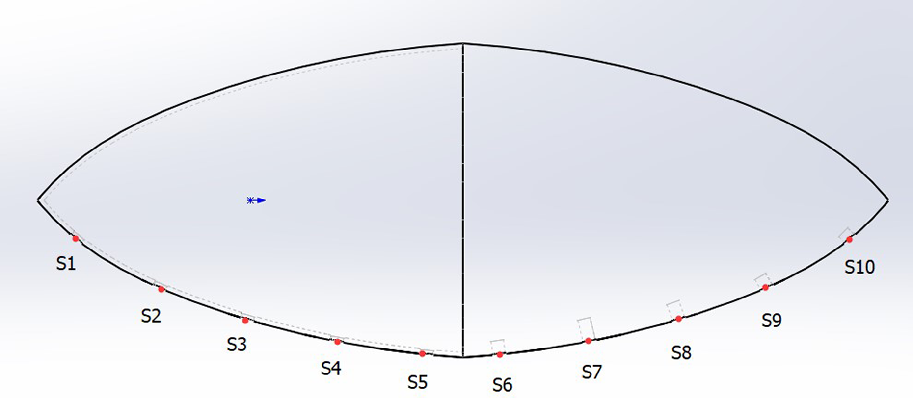
The underwater robot structure.

Three-dimensional model.
Simulation model
Simulation and modeling
According to the biological principle of fish lateral line and the shape of fish, SolidWorks is used to establish geometric model and import ANSYS to meshing and we use ANSYS FLUENT for numerical analysis fluid dynamics software. The model parameter settings are as follows: establishing a calculation domain of 4.5 m long, 4 m high, and 0.6 m wide. At the same time, the lateral-line model was placed at 20 cm below the water, and the wave was generated by open channel wave bc. Figure 4 shows the simulation model and solution region.
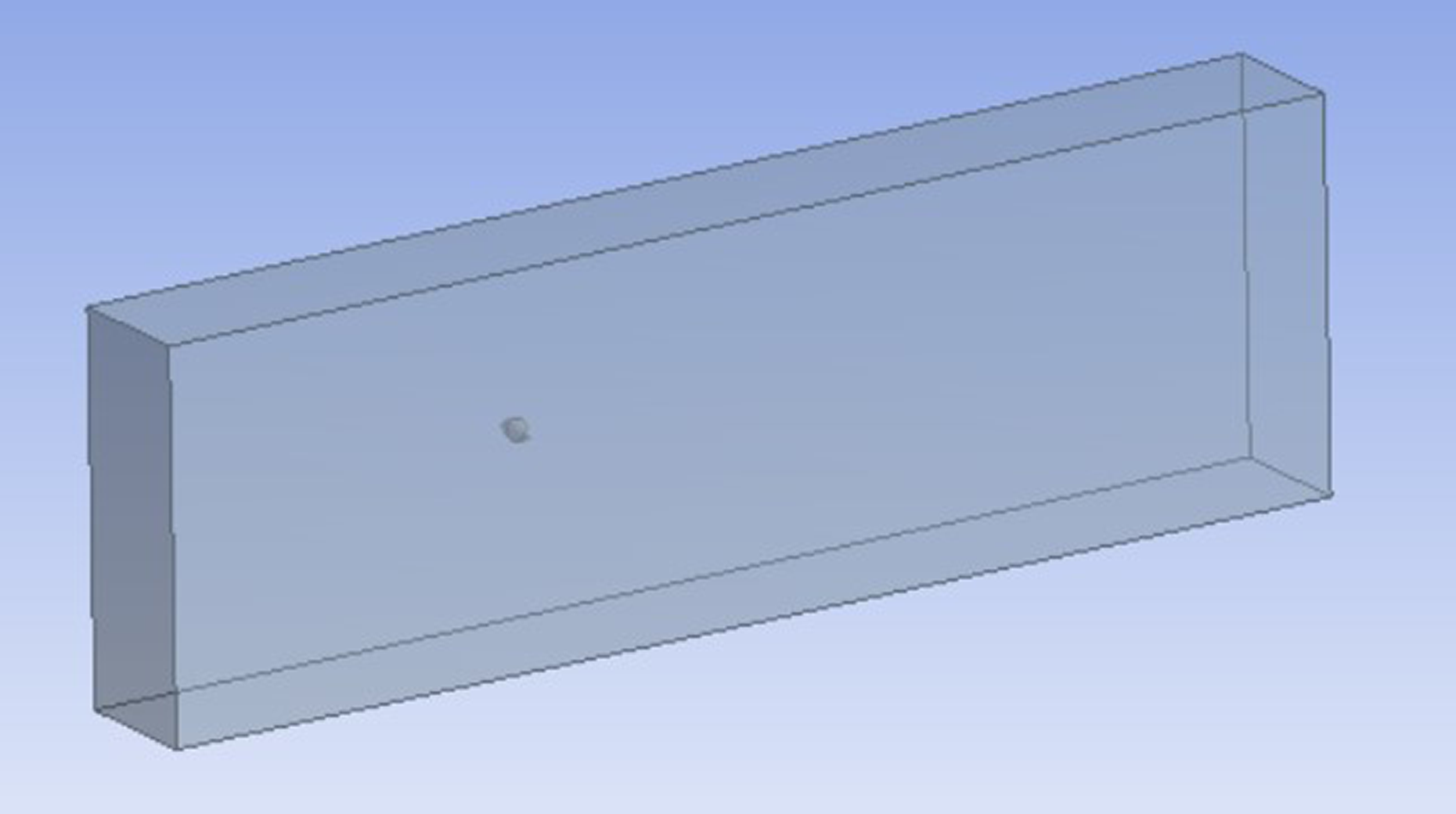
Simulation model and solution region.
Boundary conditions and parameter settings of the model
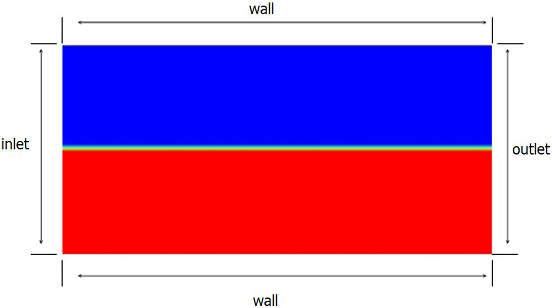
In order to simulate the real water flow field environment, the water inlet boundary is set as the velocity inlet, and the outlet boundary is set as the pressure outlet. The upper boundary can be set as wall because the airflow in the calculation domain has little influence on the wave forming process. The upper half part (the blue region) is the gas phase, and the lower part (the blue region) is the liquid phase. Figure 5 shows the calculation domain boundary condition setting.
Calculation domain boundary condition setting.
An area (red region in Figure 5) of 4.5 × 2 m2 is set as the liquid at the initial time. The physical properties of the gas–liquid two phases in the flow field are shown in Table 1.
Physical parameters of flow field calculation.

In the wave-making process, the gas–liquid exchange surface is considered as the problem of free surface problem. The volume of fluid (VOF) model is chosen as the method to solve the problem. The two-phase flow is selected and the gravity of the fluid is considered.
Simulation results and analysis
The pressure changes of S1–S8 pressure sensor were monitored by FLUENT simulation under the condition that the angle between the lateral line of artificial fish and the direction of incoming flow was 90° and 45°, respectively. 1. The lateral line with an angle of 90° to the flow direction
As we can see in Figure 6, after about 1.4 s, the force of the sensor shows stable periodic variation. The average maximum value is 15.65 N, and the average minimum value is 4.01 N. When the pressure increases, the pressure distribution of each point on the lateral line is “convex,” and the pressure distribution at each point on the lateral line is “concave” distribution when the pressure decreases. The pressure distribution is shown in Figure 7(a). At 3.25 s, the pressure distribution as shown in Figure 7(b) and at 5.68 s, the pressure distribution as shown in Figure 7(c). At 6.22 s, the pressure distribution as shown in Figure 7(d). This shows that the sensor in the middle of the lateral line is first affected by the wave force, followed by the wave force on both sides of the sensor. When the water wave leaves, the sensor in the middle first feels the wave leaving.
The pressure curve of the sensor that flows in the direction perpendicular to the lateral line.

Pressure distribution at different times on the lateral line.
Figure 8 shows the periodic distribution of pressure difference between adjacent points on the lateral line. It can be seen that the pressure difference between points 1–2 and 7–8 at the same time is largest. The difference in pressure between point 2–3 and point 5–6 points 3–4 and point 4–5 are at minimal value. The pressure difference between the sensors on the side of the lateral line is relatively low, and the pressure difference between the sensors in the middle is relatively small.

The variation curve of the pressure difference between two adjacent points.
2. The lateral line with an angle of 45° to the flow direction
As can be seen from Figure 9, after 0.9 s, the force of the sensor has a stable periodic change which is about 0.85 s and the change of pressure is not very large, with an average maximum of 8.07 N, and the average minimum is 7.44 N.

The force curve of a sensor with an angle of 45° between the side line and the water flow.
Figure 10 shows the variation of pressure difference between adjacent two points on the fish lateral line at 45°angle between the lateral line and the water flow. It can be seen that at the same time, the point 1–2 is the biggest difference, followed by points 2–3 and 5–6. The pressure difference between points 3–4, 6–7, and 7–8 decreases in turn. The closer the point of the lateral line is to the wave, the smaller the pressure difference between the adjacent two points is. The farther the point on the lateral line is away from the wave, the greater the pressure difference between the adjacent two points.

The variation curve of the pressure difference between two adjacent two points.
Experimental device and results
Our prototype possesses a 3-D printed fish-shaped body mounted with 10 off-the-shelf pressure sensors (MS5803-05BA). Two pairs of 5 V voltage supply wires and 10 analog pressure signal outputs which are inserted into the fish-shaped body through the top structure. The outer surface and joints were coated with waterproof materials to prevent water from seeping into the body. We install the pressure sensor array on the underwater robot body, as shown in Figure 11(a), and the front view after installation is shown in Figure 11(b).

(a) Sensor array connection and (b) front view of underwater robot body.
Figure 12 shows the experimental device. The experiments were performed in a tank filled with water. We fixed the underwater robot structure and placed it 2 cm below the water, and waves are periodically produced at the same location in the pool using the ball, and the force of the 10 sensors are collected in real time.

Experimental device.
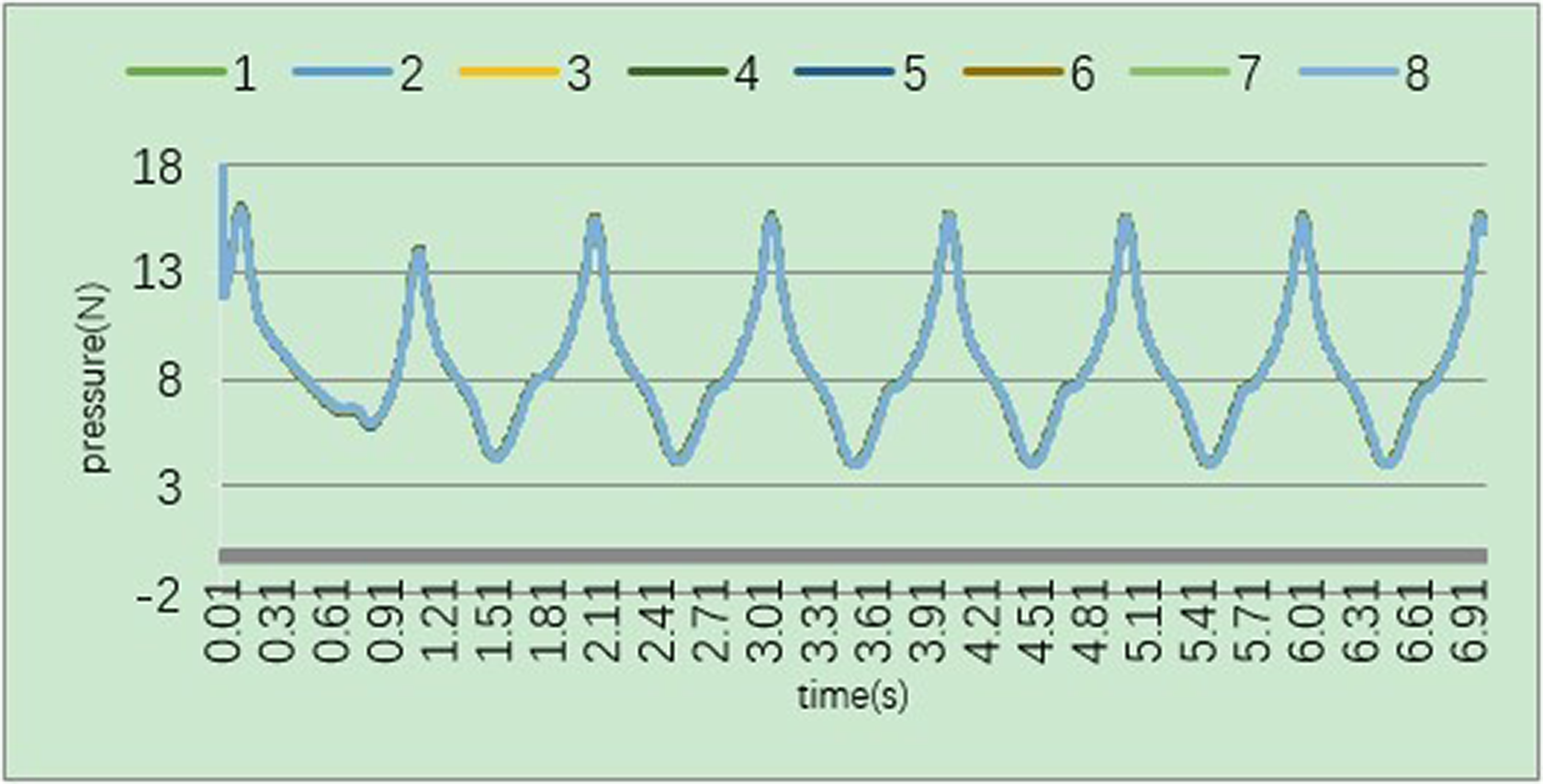
The experimental data are collected as shown in Figure 13. Because of the fish structure is symmetrical, the data of S1–S5 sensor are the same as the sensor data of S6–S10, so we choose the data of the S1–S5 sensors to compare with the simulation data. By comparing the pressure curves of the sensors in Figures 6 and 13, it can be seen that when the artificial fish lateral line is affected by water flow in the water, after 0.61 s, the pressure of the sensors collected by experimental data and simulation data shows the same periodic fluctuations and the experimental data and simulation data show that the pressure of different sensors has obvious differences and presents periodical changes. When the water wave comes, the sensor in the middle of the lateral line is first affected by the wave force, followed by the wave force on both sides of the sensor. When the water wave leaves, the middle sensor first feels the wave leaving. When the pressure increases, the pressure distribution of each point on the lateral line is “convex.” When the pressure decreases, the pressure distribution of each point on the lateral line is “concave.”

Experimental results.
By comparing the experimental data and the simulation data in Figure 14, it can be seen that the data of the 10 sensors of the artificial fish side line show the same change rule when they encounter the water flow. Thus, the rationality and accuracy of artificial fish lateral line are verified.
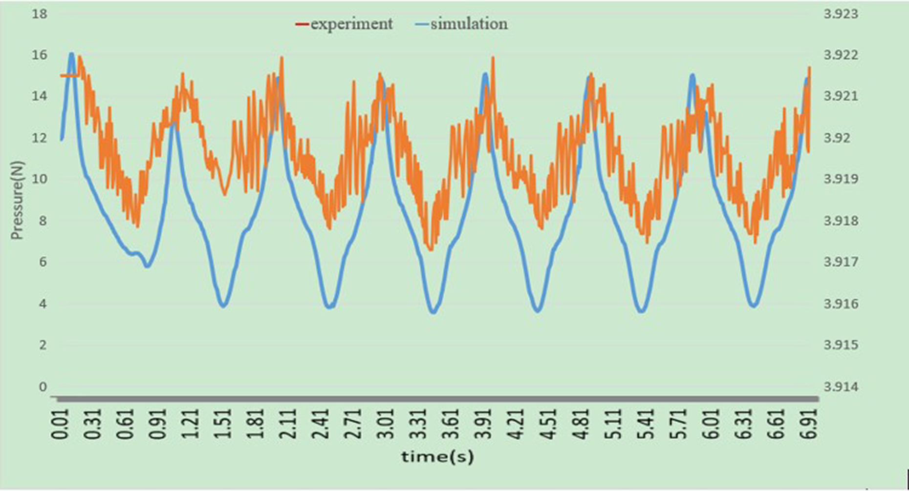
Matching graphs of simulation and experiment.
Conclusion and future works
In this article, we set up an artificial lateral-line system inspired by the fish lateral line. The pressure sensors are arranged on the fish-shaped structure which is printed by the 3-D printer. Through experiments and numerical simulation, the experimental data of the pressure sensor are obtained. The feasibility and accuracy of the artificial fish lateral line were verified by comparing the experimental data with the numerical simulation data.
There is no doubt that the artificial lateral line can be used as the sensing system of the underwater robot to perceive the change of water flow in the surrounding water environment. At the same time, the artificial lateral line can provide important environmental information for underwater robots, enable them to avoid obstacles effectively, and achieve precise attitude control, so as to ensure that underwater robots can complete complex underwater tasks.
In the near future, we will equip the artificial fish lateral line on the underwater robot and we will search for advanced classical optimization methods and intelligent control strategies based on artificial lateral-line features.
Footnotes
Declaration of conflicting interests
The author(s) declared no potential conflicts of interest with respect to the research, authorship, and/or publication of this article.
Funding
The author(s) disclosed receipt of the following financial support for the research, authorship, and/or publication of this article: This work was financially supported by the National Natural Science Foundation of China (no. 51005142, 51775323), the Innovation Program of Shanghai Municipal Education Commission (no. 14YZ010), and the Shanghai Natural Science Foundation (no. 14ZR1414900).