
Abstract
The development of skills related to computer programming and robotics and the introduction of computational thinking principles in high schools are worldwide trends today. An effective way of initiating young students in this world consists in proposing them stimulating challenges. This work presents a robotic platform that has been successfully used to develop a competition (called Drone Challenge) in which students had to program the navigation system for a simulated unmanned aerial vehicle (or drone). Both the competition and the supporting platform are described in detail. In particular, the article provides a deep technical description of the main components of the platform, namely the drone simulator and the navigation development framework. The results of the survey conducted after the challenge point to the suitability of the working platform deployed.
Keywords
Introduction
In the literature, many works can be found proposing ways to teach computer programming and, in general, to engage K-12 students with Science, Technology, Engineering, and Mathematics (STEM) subjects. Most of them are focused on robotics programming. For example, He et al. 1 describe a summer K-12 robotics course. Bower 2 discusses strategies for teaching beginner students how to program mobile robots for autonomous operation. In the study by Ilori and Watchorn, 3 a robotics mentorship program mixes undergraduate engineering students with primary and secondary ones. A robotics unit is integrated into a fourth-grade science curriculum. 4 West et al. 5 rely on Arduino-based robot kits and real and simulated exploration rovers. In many cases, these proposals are based on the development of robotics challenges for students, such as the well-known RoboCupJunior, 6 the IT-Adventures, 7 the Junior Soccer Simulation, 8 and the Zero Robotics 9 competitions. Game-based learning environments have also been used to motivate young students. This is the case of the LOGO-like environment proposed by Paliokas et al. 10 and the robot game environment described by Shim et al., 11 which combines tangible user interfaces with an educational robot.
At the same time, there is a new trend in K-12 education, referred to as computational thinking. Computational thinking is based on the principle of applying concepts and practices borrowed from the computer programming world to solve problems in any discipline (not only the computing one). Computational concepts include sequences, loops, conditionals, operators, and so on. Some examples of computational practices are experimentation and iteration, testing and debugging, abstracting and modularizing, and reusing and mixing. Since the seminal work of Wing, 12 the number of initiatives introducing these ideas in the teaching/learning process at K-12 level has notably grown. A complete review of such efforts can be found in the study by Heintz et al. 13 Perhaps the most popular approaches are the Scratch, 14 Blocky, 15 and Code.org 16 block-based (or visual) programming environments. Turchi and Malizia 17 suggest extending this kind of environments with tangible user interfaces. Alternative initiatives to block-based coding 18 rely on digital storytelling, and studies in the literature 19,20 propose using robotics (like the current work) for promoting computational thinking. Visual programming and robotics also meet at the popular Makeblock platform 21 and in the LEGO-based platform described by Yadagiri et al. 22 Finally, García-Peñalvo and Mendes 23 explore the effects of recent computational thinking experiences in pre-university education.
In this context, and with the goal of promoting skills related to computer programming and robotics among the secondary school students of the Spanish region of Castilla-La Mancha, the Faculty of Computer Science Engineering of the University of Castilla-La Mancha 24 designed a drone programming competition consisting in the development of the automatic navigation system for an unmanned aerial vehicle. 25 The name of this competition is Drone Challenge, 26 and its two first editions were carried out from April to June 2017 and from February to April 2018, respectively.
In this work, aside from describing the goals, rules and phases of the competition, and the way in which it was carried out, we present in detail the working platform deployed for the participants, since we consider that it is an excellent baseline for the development of computer programming skills at K-12 level. At a glance, the platform allows the students to design their proposals using a development environment based on Matlab/Simulink [version: R2017a, MathWorks]. 27 Then, they can evaluate the performance of their designs in a simulation environment based on the robot operating system (ROS) 28 and Gazebo. 29 Furthermore, the article provides the results of a survey conducted after the competition with the aim of collecting the participants’ opinion about the tools employed and the development of the challenge.
To sum up, the main contributions of this work are threefold: (1) the proposal of a complete robotic platform for the development and test of drone navigation systems; (2) the description of a challenge for secondary students based on this platform; (3) an evaluation of both the platform and the competition, based on the opinions provided by the participants in the event.
The rest of this work is structured as follows. First, in the second section, the Drone Challenge competition is described. Then, in the third section, the working platform is detailed. After that, in the fourth section, the contents of the survey proposed and an overview of the responses collected are presented. Finally, in the fifth section, conclusions and some future works derived from this work are summarized.
The drone challenge competition
Drone Challenge is a contest for student teams, in which each of them must program the automatic navigation system for an unmanned aerial vehicle (from now on, just “drone”). The drone considered is a quadcopter, since this is the most popular type of drone today. In fact, although navigation systems are tested in a simulation environment, the final prize is a commercial drone for each one of the components of the winner team.
In particular, each team must provide some intelligence to a simulated quadcopter, so that it is able to take off from a base, cross several floating frames in a specific order (red, green, and blue), and finally land over the starting point. Figure 1 shows the competition arena, in which we can observe the colored frames, the drone on its takeoff base, and a golden carpet identifying the allowed flying area. We assume that the drone is equipped with a camera, which helps in the process of locating the frames. Each milestone (crossing a frame, crossing all the frames in the right order, and landing over the starting point) provides a point for the try. In case of a tie, the time of each try is also considered.

The competition arena.
Obviously, the solution to the challenge is not unique. Each team can choose its own strategy for the drone navigation system. At the same time, the performance of two implementations for the same strategy may be different, resulting in different flight times. Therefore, the challenge proposed stimulates the creativity of the participants. This concept is very close to the concept of computational thinking. Indeed, the expressions “creative computation” and “creative thinking” are often used as synonyms or complementary of computational thinking.
To evaluate the quality of each proposal, the navigation system developed is tested in different scenarios (or simulated worlds), in which the position of the colored frames, the takeoff base, and the drone’s initial orientation vary. Ideally, the drone should exhibit exactly the same behavior (taking off, crossing the frames in the right order, and landing) in all of them.
Although students have to deal with several complex tools, an effort has been made to adapt these tools to their level, not being required to have previous experience with them. Also, there are lots of low-level implementation details such as the drone stability control, the way in which video is processed, and the public–subscribe protocol used for the communication between tools, which participants do not need to know to develop their proposals. Third section focuses on all these implementation aspects.
Regarding the phases of the competition, there is an initial phase, which lasts between 8 weeks and 10 weeks, in which the enrolled teams have to develop their proposals in their respective schools. Then, the submitted navigation systems are assessed to determine the set of teams that will finally participate in the final phase of the competition. In the first edition of the competition, 20 teams coming from all the provinces of the region of Castilla-La Mancha were enrolled in this initial phase. In the second edition, the number of enrolled teams grew to 62. Since each team is composed of two, three, or four students supervised by a teacher, more than 80 people in the first edition and 260 people in the second edition were working in their proposals during this phase of the competition.
The final phase took place in the facilities of the Faculty of Computer Science Engineering, on June 30, 2017 and on April 23, 2018. Only 7 teams, involving a total of 30 people, and 14 teams, involving a total of 59 people, participated in this final phase in each edition. Regarding the scheduling of the final phase, during the first hour, teams test their navigation systems in seven different scenarios, and they can make last-minute tunings to their implementations. Then, all the proposals are frozen, and three of the previous scenarios are randomly chosen. During the last hour of the final, proposals are tested in these three scenarios under the supervision of the judges of the competition.
A supporting application, the Game Monitor, is available for the participants during the initial phase of the competition, so that they can know and improve the quality of their proposals, and it is also employed by the judges during the final phase. It is a separate Matlab/Simulink program that connects to the simulation environment to measure the time required to complete each try. In particular, while the simulation is running, it provides the time during which the drone engines are on and shows the location of the drone in a top view of the scenario (see Figure 2). This tool is also in charge of checking whether the drone exits the flying scenario (a 10 × 10 × 4 m3), since this situation must be penalized (see Figure 3), and whether the try has reached the maximum allowed time (set to 3 min).
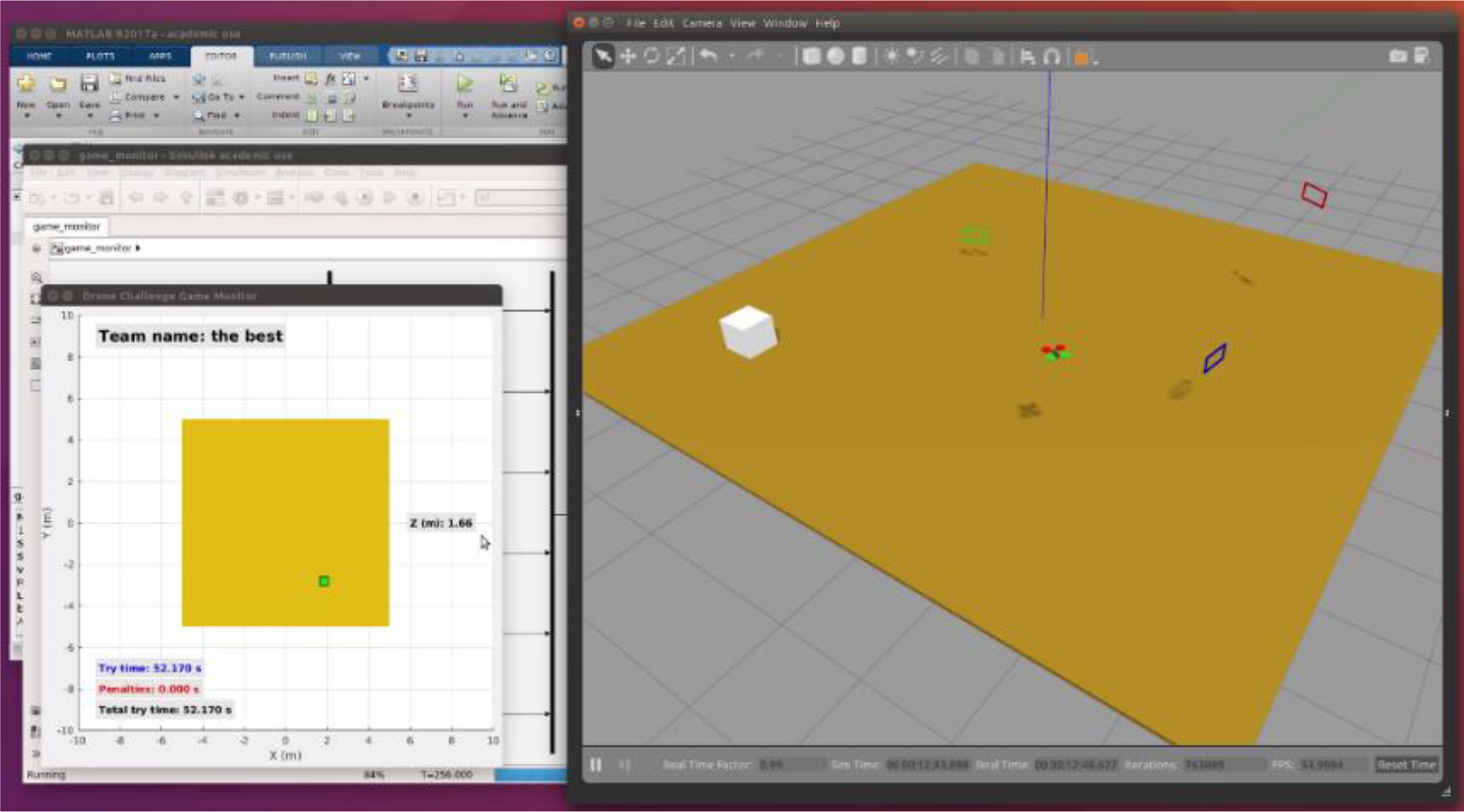
Game monitor snapshot.

Game monitor snapshot (drone out of the scenario).
Apart from the Game Monitor, a small client–server application was developed for the final phase so that, while the judges of the competition are assessing proposals, participants can check their “virtual” place in an instantaneous ranking. To have this ranking updated in real time, each judge uses a smartphone to fill in a Web form with the results of each try and sends immediately this information to the server.
Finally, with respect to the interaction with the participants during the competition, it is mainly supported by its “official” blog, 26 which has been conceived as a dynamic tool. In this space, students can access to a set of video tutorials organized in several categories. Figure 4 shows an example. Through these tutorials, the organization provides detailed instructions for installing and configuring the working environment and gives advice and suggestions for the development of the proposals. These tutorials also offer solutions to the problems or doubts that the participants pose as they work on their designs. On average, each of these tutorials has received more than 100 views during the first edition of the challenge and more than 160 views during the second one. Video tutorials are complemented by the traditional “Frequently asked questions” section of the blog.

The “how to cross a frame” video tutorial.
The robotic platform
The working environment employed by the participants in the Drone Challenge competition described in the previous section is composed of two main components: a drone simulator and a navigation development framework. Next, we detail both components. As said above, most of the details provided here are hidden for the students, but they would be available if we wanted, for example, to use this platform for designing a different competition or for teaching purposes.
Drone simulator
The drone simulator (Figure 5) is based on Gazebo, 29 a realistic robotics simulator included in the popular ROS. 28 It runs on Ubuntu and allows testing the navigation system programmed in a simulated scenario. Students just must launch the Gazebo simulator, specifying the name of the scenario in which their program will be tested.

Drone simulator developed in Gazebo.
This subsection focuses on the design of the drone model incorporated into the simulator. As we will see, we have used Simulink for solving the model. Then, the solution obtained has been programmed in the ROS/Gazebo plugin managing the simulated drone.
Quadcopter state-space model
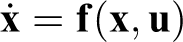
To model and control the drone, we have used the state–space theory of linear time-invariant systems. 30 At first, the nonlinear system dynamics is represented by the following state and output equations

Where
First, the system input vector
From now on, we will use the

Drone reference system (X axis in red, Y axis in green, and Z axis in blue).
Let vector

Drone position and orientation (odometry) in Simulink.
Considering that the drone behavior does not depend on its location, from the point of view of the sustentation control we do not need the information provided by
Finally, we define the output vector
Nonlinear drone dynamics
After defining the input (
Translation movement is given by the set of forces acting over the object, according to the expression

Use of the 6-DOF Simulink block. DOF: degree of freedom.
The drone modeled looks like the one shown in left side of Figure 9. Rotors are arranged in a square, and they are located at 25 cm from the center of gravity. Each propeller covers a circumference of 20 cm in diameter. We have considered a mass of 300 g, and a total inertia equal to the inertia of a 40 × 40 ×5 cm3 box with uniform density. The right side of Figure 9 shows the drone inertial properties, defined according to the simulation description format (SDF) specification.
31


Quadcopter aspect and inertial properties.
Translation equations
The set of forces contributing to the drone translation movement are given by the expression

Drone translation movement.
The 6-DOF Simulink block requires input forces and moments expressed in the drone coordinate system. However, the gravity is initially defined with respect to the earth coordinate system, as

Gravity force in the drone coordinate system.
The angular speed of each rotor is
We define the aerodynamic thrust force T as the one produced (in opposite sense) by the air pushed by a propeller. This force is proportional to the square of the propeller rotation speed Ω, that is,
Altogether the four drone rotors will produce a resultant force (

Figure 12 shows the Simulink model implementing this force.

Aerodynamic thrust force.
Finally, we define the aerodynamic drag force (

In our model, the
Figure 13 shows the Simulink model implementing this force.

Aerodynamic drag force.
Rotation equations
As said before, the moments contributing to the rotation movement experienced by the drone are given by the expression

Moments involved in the drone rotation.
Next, we describe these moments, called aerodynamic thrust (
We define the aerodynamic thrust moment (

Regarding the (longitudinal) X axis, rotors producing a positive moment are those located on the left side (NW and SW). On the other hand, regarding the (perpendicular) Y axis, rotors producing a positive moment are those located on the rear side (SW and SE). Since

Aerodynamic thrust moment.
The turn of a rotor produces a drone rotation in opposite sense. Rotors can turn at different speeds, according to the sense indicated in Figure 16 left. Collectively, this produces a rotor aerodynamic drag moment (

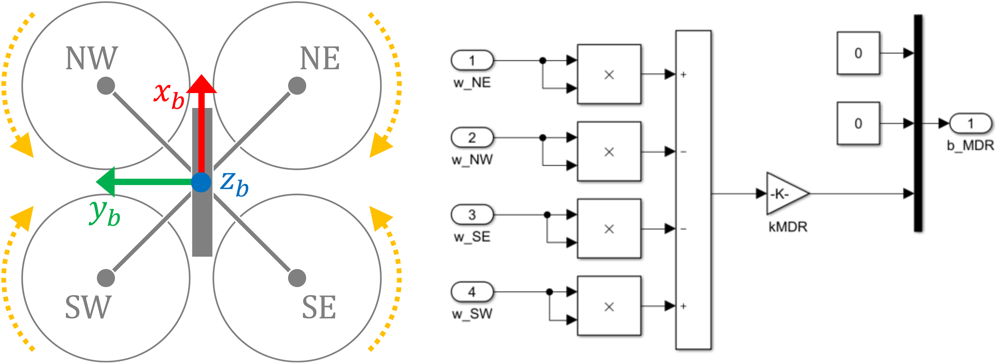
Drone rotors and rotor aerodynamic drag moment.
Finally, we define the aerodynamic drag moment (

Again, we assume similar frictions in the X and Y axes. The

Aerodynamic drag moment.
Linearization
After modeling the above equations in Simulink, they are linearized using the linear analysis tool. Figure 18 shows the complete system, with the input and the output in open loop. The operating point applied is the drone perfectly balanced, with null linear and angular speeds. The input is similar for all the rotors, so that each one compensates a quarter of the weight of the drone.

Drone non-linear model.
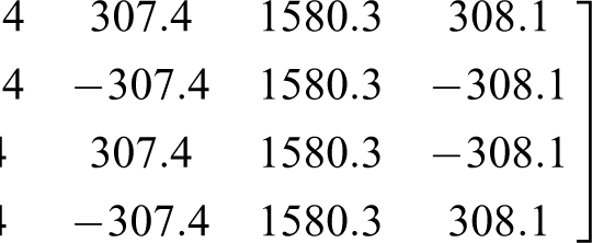
After the linearization, we obtain the transformation for the initial system expression, where the values obtained for the state (


Low-level control
We have defined previously the system output as
Once we have linearized the nonlinear system modeling of the quadcopter, we apply a controlled feedback of the state and the accumulated error (


To compute the control matrices

Then, we define a new system, modeling the follow-up error

Since the obtained system does not have an input, we can apply the pole placement method. The chosen eigenvalues are

To conclude this subsection, we will outline the behavior of the ROS/Gazebo plugin developed after solving the model. Each simulation cycle starts by reading the drone X and Y values. Then, considering the proposed reference, the instantaneous error is computed. The result of this computation is used to update the accumulated error. After that, the set of matrix operations previously described are performed, producing the rotation value for all the rotors. As a result, the drone follows the given reference.
Navigation development framework
The navigation development framework (Figure 19, left panel) is based on the popular engineering tool Matlab/Simulink, 27 which can be run over different operating systems (including Microsoft Windows, macOS, and Ubuntu). Students define the drone’s behavior by programming the autopilot block on the left. As we will see, it can be done in an easy and visual way, by means of a reduced set of commands. Note that it is also possible to control the drone manually using a joystick. The drone simulator block on the right employs the Matlab Robotics System Toolbox 32 to connect to Gazebo through several ROS topics (Figure 19 right panel).

Navigation development framework (high-level view).
Quadcopter odometry
Gazebo continuously publishes on a ROS topic, to which Simulink is subscribed, a vector

ROS topic publishing quadcopter odometry. ROS: robot operating system.
Video image processing
The model also receives the video frames acquired by the drone’s built-in camera. This camera presents the following characteristics: Refresh rate: 5 Hz Resolution: 320 × 240 pixels Color range: 24 bits/pixel Angle of view: 90° Projection plane: 160 cm from the focal point.
All the above means that, if we place a frame on the projection plane, its size in pixels on the image corresponds to its actual size in centimeters.
Each frame is automatically processed, looking for any colored pixel. Figure 21 shows an example of this processing. Plot on the right shows the red and blue frames detected in the image shown on the left. The result of this processing is available for the programmers through the cam bus. More in detail, this bus is composed of three fields (called, respectively, red, green, and blue) that provide the limits of the image region where the corresponding frame has been located, referred to as N (north), S (south), E (east), and W (west) (see Table 1).

Example of video image processing.
Data provided to the programmer in the example of Figure 21.

N: north; S: south; E: east; W: west.
From this information, we can conclude whether a frame is completely displayed on the screen. If so, knowing that the actual height of each frame is 23 cm, we can infer the distance X to it by applying the method shown in Figure 22.
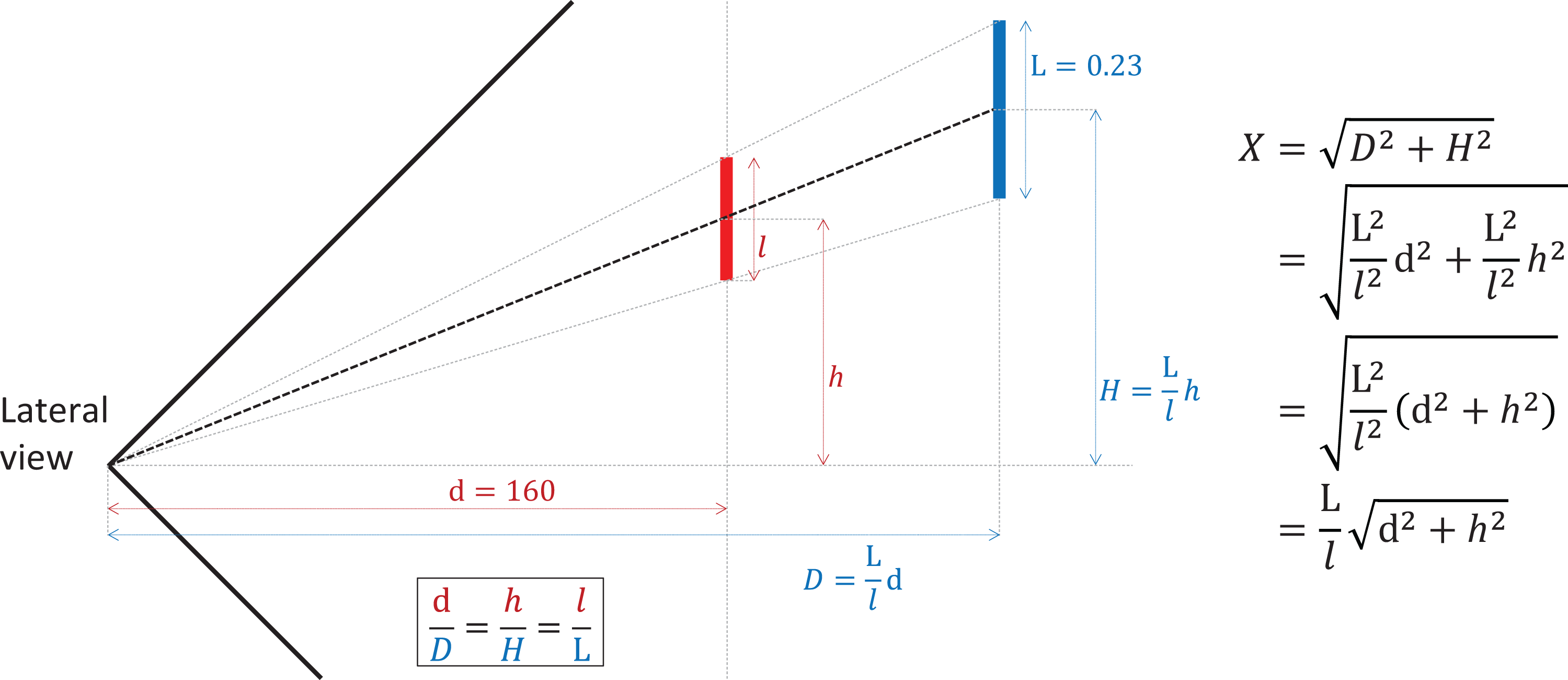
Distance to a frame.
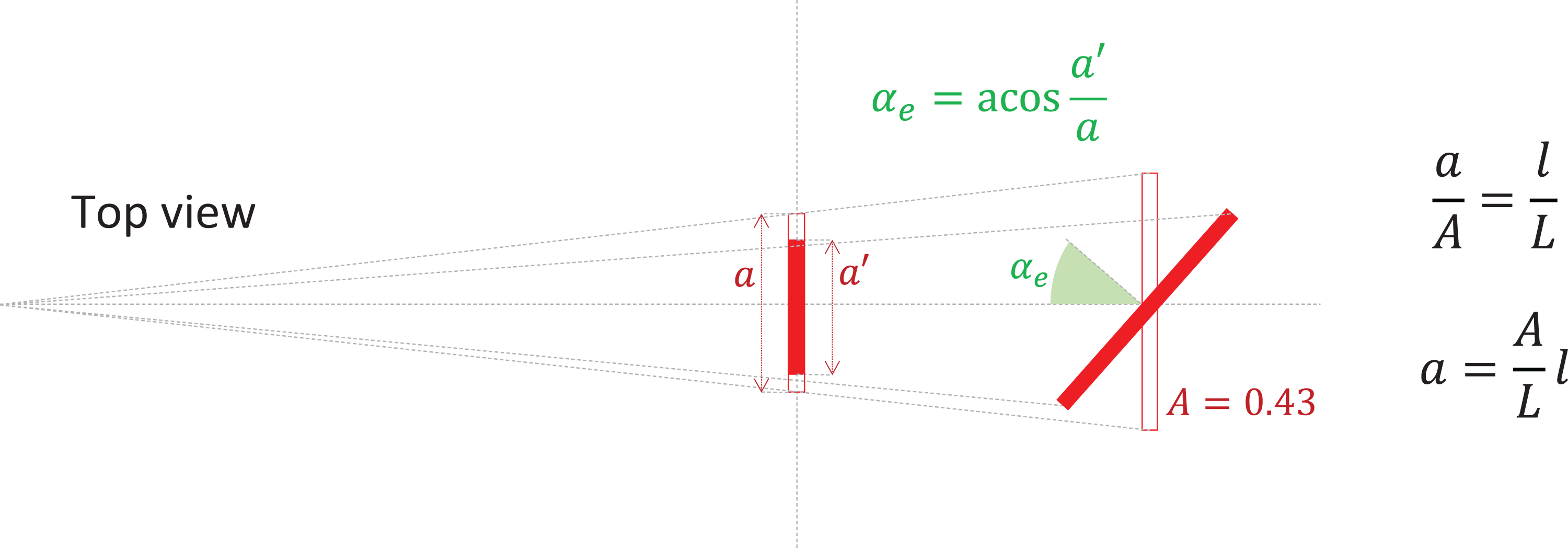
In the same way, once the distance has been computed, and knowing that the actual width of each frame is 43 cm, we can infer the angle of inclination (in absolute value) with which we approach by means of the procedure shown in Figure 23.
Angle of inclination.
The following Matlab code fragment implements these computations:

Quadcopter navigation
Programmers control the movement of the drone by setting five variables composing the cmd bus (Figure 24 left). This bus publishes data into a ROS topic to which Gazebo has been previously subscripted. For debugging purposes, this bus is monitored by means of a Simulink viewer (Figure 24 right).

ROS topic publishing quadcopter commands. ROS: robot operating system.
The on variable is a binary value used for activating or deactivating the drone engines. If it is set to 0, the drone will drop. Otherwise, it will move according to the rest of control variables. The velX, velY, and velZ variables are real numbers between −1 and +1 that provide the drone with different velocities according to the drone reference system (see Figure 6). Finally, the rotZ variable is also a real number between −1 and +1 that allows to define a horizontal turn (around the Z axis).
Programmers define the value for these variables from a state machine implemented in Stateflow (inside Simulink). The use of this tool is very easy and intuitive. Figure 25 shows two examples. According to the state machine shown on the left, the drone continuously starts the engines, ascends until it reaches an altitude of 2 m, stays in this position for 3 s, descends until it reaches an altitude of 0.7 m, and finally stops the engines. According to the behavior shown on the right, the drone ascends, and then, maintaining its altitude, it moves to a specific scenario position (defined by X = 2 m and Y = 3 m). Finally, it lands on the floor.
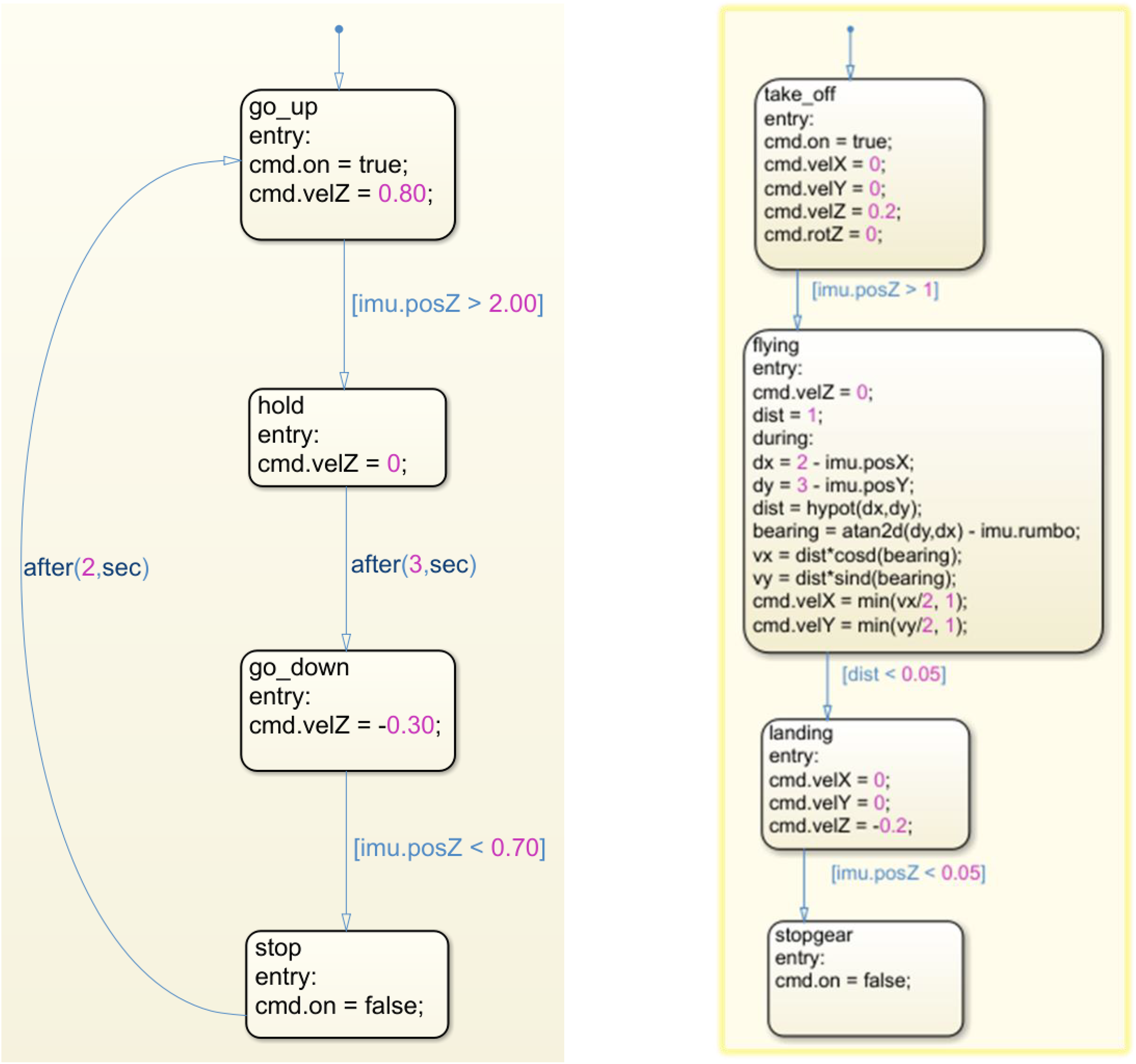
Two examples of drone behavior programmed in stateflow.
Survey for participants
After the second edition of the Drone Challenge competition, we asked the participants to answer an anonymous and voluntary online survey to collect their opinion about different aspects of the challenge. It was answered by exactly 36 people (19 students and 17 teachers), 34 of whom attended to the final phase of the competition. Therefore, we consider that their opinions can be representative enough.
The survey was composed of two parts. Questions in the first part tried to determine the participant’s profile. In particular, they were asked to indicate their educational level, their background in programming and robotics, and their interest in studying a STEM degree (in case of being a student). Table 2 details the questions composing this part of the survey. As it can be observed in this and the following tables, instead of using a Likert-type scale, most of the questions are Yes/No questions. The reason for this decision was that we tried to maintain the concentration of the young students until the end of the survey, composed of 24 questions.
Questions related to the participant’s profile.

STEM: Science, Technology, Engineering, and Mathematics.
a Spanish curriculum at secondary level (high school) considers first a four-year mandatory stage, for students from 12 to 15 years old. This stage is called “Enseñanza Secundaria Obligatoria (ESO).” Then, there is a two-year stage, referred to as “Educación Secundaria Superior,” for students between 16 years and 17 years. In this period, students can take the “Bachillerato,” oriented to academic degrees, or a “Ciclo Formativo,” focused on the labor market.
From the responses provided by the participants, we can firstly observe that three quarters of the students come from the “Bachillerato” educational level (see Table 3), that is, they are about to enroll in an academic degree. According to Table 4, we may conclude that less than half of the students are familiar with programming and robotics. On the other hand, most of the teachers have some background in programming, but they are not so familiar with robotics (questions Q3 and Q4). Both findings are not surprising if we analyze the current curriculum at secondary level. Aside from that, nearly all the students expressed their interest in enrolling in an STEM degree (Q5). Most of them were interested in a computing engineering degree.
Responses to question Q2 (Educational Level).

Responses to Questions Related to the Participant’s Profile.

The second part of the conducted survey was composed of three blocks. The first block (see Table 5) was focused on polling the opinion of the participants regarding the set of tools composing the working environment and the utility of video tutorials.
Questions related to the working environment.

ROS: robot operating system.
According to the responses collected (see Table 6), the general opinion about both the development and simulation environments was positive (Q7 and Q10). However, some of the participants complained about the computational power required to run the simulation environment. We believe that the reason is that many of them employed Linux virtual machines for running ROS and Gazebo. Another reason could be the amount of issues when starting Gazebo (in both the real and the physical machine). Finally, most of the participants found video tutorials useful in preparing the working environment and designing their proposals (Q11 and Q12).
Responses to questions related to the working environment.

Then, the second block (see Table 7) was focused on the opinion of the participants about the way in which their proposals had been assessed. This block of questions was addressed to those teams that reached the final phase of the competition.
Questions related to the evaluation of proposals.

From the corresponding responses (see Table 8), we must highlight that a high percentage of both students and teachers believed that their proposals had been evaluated fairly. In addition, most of them knew the assessment procedure.
Responses to questions related to the evaluation of proposals.

Finally, the third block (see Table 9) collected the general opinion and feelings about the competition. This block was opened to all the participants in the competition (not only to those attending to the final phase).
Questions related to the opinion about the competition.

The responses obtained in this last block of questions (see Table 10) showed that, although more than a half of the participants considered that the required technical level was appropriate, there was not a complete consensus about it (Q17). Perhaps the reason for this is that at this educational level there is a generalized lack of familiarity with the Matlab/Simulink tool, as we can see in the responses provided to questions Q8 and Q9 (in Table 6). On the other hand, we can see that most of the responses to questions Q19 to Q21 were positive. Therefore, we may conclude that participants enjoyed their participation in the event. Moreover, most of the responses to question Q23 were also positive, which shows that students are willing to participate in future editions of the challenge.
Responses to questions related to the opinion about the competition.

Conclusions and future works
In this work, we have presented a platform for the development of programming and robotics competitions for young students, such as the Drone Challenge event described. We consider that this platform is a suitable tool for being used to practice different aspects related to computer programming and aerial robotics at K-12 level. Furthermore, this framework may also be used for supporting robotics subjects in engineering degree programs, since, as we have seen, it allows to work at different abstraction levels.
The results of the survey conducted after the Drone Challenge competition indicate that participants had a very positive opinion about the working platform and the way in which the competition had developed.
As future works, after solving the issues related to the simulation environment (or, alternatively, replacing it by a real drone platform), we plan to use this tool as a starting point for the design of future programming challenges for secondary school students. We also believe that this framework could be useful to develop a research line on autonomous navigation for flying robots.
Footnotes
Declaration of conflicting interests
The author(s) declared no potential conflicts of interest with respect to the research, authorship, and/or publication of this article.
Funding
The author(s) disclosed the receipt of following financial support for the research, authorship, and/or publication of this article: This work has been partially supported by the TIN2015-66972-C5-2-R (MINECO/FEDER) project.