
Abstract
A motion control approach is proposed for hydraulic actuated quadruped robots, aiming to achieve active compliance and robust motion control. The approach is designed with a structure of three layers. Servo valve-controlled asymmetric hydraulic cylinder model is established to obtain the relationship between the desired torque and the control current signal, which is the bottom layer. The middle layer is based on the virtual model of the leg for active compliance. The upper layer considers the torso posture and velocity into planning the foot trajectories based on the spring loaded inverted pendulum model. Trotting gait simulations are conducted based on the proposed framework in the simulation software environment Webots. The motion control approach has been implemented on a robot prototype SCalf-II (SDU calf), where experiments have been conducted including omnidirectional trotting gait, lateral impact recovery and climbing slopes. The experiments demonstrate that the proposed approach can effectively control the hydraulic actuated robots.
Introduction
Quadrupeds in the nature like goats, horses and cheetahs show a great advantage of agility and versatility in running, climbing, balancing on uneven terrain and so on. The quadrupeds are inherently stable than bipedal animals and simple in structure compared to the hexagonal. In recent years, many researchers have shown great interests in building quadruped robots.
Our purpose is to design a quadruped robot that has the animal-like dynamic motion behaviour and high payload capacity. To achieve this goal, actuators need to be selected deliberately. Compared to electric actuators, the hydraulic actuator is an ideal choice for highly dynamic robots as it is compact and durable with fast response speed and large output force. 1 The hydraulic actuators are easy to implement in the system and efficient in increasing the force capabilities even without gear transmissions compared to the electric motors. They can withstand high external disturbance robustly. They have a substantially higher power to weight ratio than the electric drives. All the joints of the SCalf-II robot (Shandong University) are actuated by the hydraulic actuators.
Dynamic motions of the quadruped robots have been studied for years, and many control methods have been proposed. Zero moment point (ZMP) method is often used to realize locomotion control, which have been implemented on small quadruped robots like littledog. 2,3 Ryo et al. 4 proposed a 3-D sway compensation trajectory that enables the quadruped robot to keep ZMP on the diagonal line of the support legs. Dynamically stable walking on unknown and rough terrain was tested on the TITAN-VIII by employing the 3-D sway compensation trajectory and posture control method. The capture point method was proposed for the legged locomotion control. 5 Jerry et al. 6 proposed a Center of Pressure (CoP)-based trajectory generation method to achieve the rough terrain locomotion. 6 Bai proposed a body trajectory planning by virtue of a terrain evaluation to obtain the optimal path. 7,8 However, all these control methods could not adapt to complex terrains or resist external disturbances.
Central pattern generator (CPG) network is a popular choice when it comes to the quadruped robot trajectory generation. Kimura et al. proposed a CPG-based neural network with reflex feedbacks to control the Tekken robot and realize the trotting gait. 9 CPG has been used to calculate the ZMP trajectory to produce walking gait. 10 CPG-based smooth trajectory generator and an attitude controller is used by the HyQ robot, 11 which is built by the Italian Institute of Technology. The CPG-based control method provides an effective way to realize locomotion control especially in the rough terrain. However, the locomotion generator is complex and parameter sensitive.
The most famous approach for controlling legged robots is the three-part locomotion algorithm proposed by Marc Raibert, 12 who has designed and accomplished locomotion control in monopod, biped and quadruped robots. The BigDog robot, which is built by the Boston Dynamic company, is a milestone of quadruped robots featuring high motion performance and dynamic gaits. Its control approach is based on Raibert’s three-part locomotion algorithm. 13 Other quadruped robots like LS3 and Spot developed by the Boston Dynamic company are considered to apply the same control algorithm even though without details in published information.
To ensure robustness against disturbances caused by terrain irregularities or slippage, to protect the hardware from damage through unexpected collisions and to safely cooperate with human collaborators, many compliant control methods for legged robots have been proposed. Passive compliance is usually obtained by applying springs or other elastic components in the structural design. 14 For example, the serial elastic actuator (SEA) is applied by many legged robots such as the StarlETH. 15 Many legged robots use sophisticated cable pulley systems that allow concentrating all the actuators in the robot base to achieve mechanical compliance. However, for heavyweight legged robots over 100 kg, it becomes hard to implement the SEAs or cable transmission in the actuation system.
Active compliance is usually achieved via control of the joint torque or contact force at the foot. A proper processing of the dynamic relationship at the contact point brings additional benefits to overall control of the robot. Model-based approaches such as inverse dynamic feedforward control are often implemented. 16 Impedance or admittance control can significantly increase the versatility and compliance of the robot. 17 Using high gain proportional–derivative (PD) servo controller with an admittance controller, which decreases the stiffness when force error appears, the HyQ robot achieves active compliance. 18 Virtual model control (VMC) is widely used in legged robots. 19 The StarlETH uses VMC to improve the adaptive abilities to different terrains. 15 The compliant feature is not only desirable but essential for legged robots to improve adaptive ability in complex terrains.
In this work, a novel control approach for the quadruped robot is proposed, which consists of three layers from bottom–top, from the actuators to the legs and then the entire robot. The proposed method is robust for the quadruped robot to achieve dynamic motion in different terrains. In detail, advantages of the proposed approach can be summarized as follows: The proposed approach is a complete control algorithm for the hydraulic actuated robot, which covers the torque control of actuators, the VMC of single leg and the motion control of the robot. The three parts are decoupled that other legged robot platform can partially or fully borrow from this approach to control their robots. The control algorithm has a good robust performance for the legged robot because active compliance and self-adjusting gait are considered to design the motion controller. The locomotion control approach can automatically adapt to the environment and external disturbance. Slope climbing and high stair adaptation strategies are proposed to improve the adaptive ability to the environment. Other control strategies can easily be incorporated into this algorithm.
This article is organized as follows. The second section depicts the kinematics of the SCalf-II robot. The hydraulic actuator model is deduced in the third section, where the VMC approach for realizing active compliance is described. In the fourth section, a spring loaded inverted pendulum (SLIP)-based approach for locomotion is described and the performance-improving strategies including terrain adaptation and slope climbing are detailed. Experimental and simulation results obtained from the robot prototype as well as simulation model are described in the fifth section. Achievements and shortcomings of the locomotion controllers used in the SCalf series of robots are discussed in the sixth section. Finally, conclusions are given in the last section.
Kinematics of robot
This section details the structure and parameters of the quadruped robot SCalf-II. The joint angle and torque are calculated based on these parameters. Then, kinematics-related formulations of the leg are derived as the basic law of motion.
Structure and parameters of the SCalf-II
SCalf-II is a hydraulic actuated quadruped robot, which is around 1.1 m long, 0.45 m wide, and 1.1 m high with fully extended legs, as shown in Figure 1. The total mass of the robot is about 120 kg. The robot has an onboard power station driven by a gasoline engine (Rotex 125) that rotates at 8000 r/min. The engine drives the variable pump and the hydraulic pressure station to provide stable 19 MPa pressure in the pines. Each leg consists of three rotating joints: the roll joint used for adduction and abduction at the hip (Hip A/A), the pitch joint used for flexion and extension at hip (Hip F/E) and the pitch joint used for flexion and extension at the knee (Knee F/E). Each joint is actuated by a hydraulic cylinder which is controlled by a servo value with position and force sensors.

Overview of the SCalf-II. (a) The quadruped robot SCalf-II and (b) structure of one leg.
The SCalf-II has four identically constructed legs so the parameters are same in the coordinate frame at hip joint of each leg. Forward kinematics and inverse kinematics in hip coordinates are in the same form because of the same structure of the leg. Figure 2 shows the left hind leg of the SCalf-II, and θ0, θ1 and θ2 are defined as the joint angle of Hip A/A, Hip F/E and Knee F/E, respectively. The masses of the Hip A/A, Hip F/E and Knee F/E and their linkages are 3.00 kg, 3.64 kg and 1.42 kg, respectively. The hydraulic servo units are installed in the Hip A/A and Hip F/E, where each weighs 1.68 kg. Compared to the total mass of the robot, the mass of each leg is very small, so in the control model, we simplified the leg into a massless bar model. The kinematics equations are based on these joint angles, which can be obtained by analysing trigonometric function of the output length of hydraulic cylinder and structure parameters


Leg parameters for kinematics: (a) front view and (b) side view.
The specification of leg parameters is shown in Table 1. The joint torque can be obtained by a cross product of the actuator force and its force arm

where f0, f1 and f2 are the forces measured by the force sensors at the joint Hip A/A, Hip F/E and Knee F/E, respectively.
Specifications of leg.

Kinematics of the leg
Kinematic equations of the leg are needed to achieve motion planning, and the leg motion execution requires inverse kinematics calculation. The kinematic equations of the leg is deduced as follows

By solving kinematic equations, the inverse kinematics of the leg can be written as

Differentiating equation (3), we can get the Jacobin matrix of the leg, which establishes the relationship between the joint space and the end-effector space of the leg.

where c0 and s0 denote
Leg controller modelling
This section details the active compliance control of the hydraulic actuators. Firstly, the hydraulic actuator model is established to get the relationship between the output force and the input current. Then the virtual model of the leg is built to achieve active compliance. The controller for actuators and legs is the foundation for the locomotion control of the robot.
Hydraulic actuator modelling
The schematic of the valve-controlled hydraulic cylinder is shown in Figure 3. To control the output force, the mathematical relation between the force and the valve input current

where q is the hydraulic flow, Kv is the valve property gain, K1 is the valve input current to the valve spool position gain, K2 is the hydraulic pressure to the valve spool position gain and Pa and Pb are the pressure in chambers a and b, respectively.

where

The model of the hydraulic cylinder controlled by a servo valve.
To simplify the output force for engineering realization, we choose

where

Considering the viscous friction we can get

where B is the viscous coefficient.
Taking account of equations (6) to (10), the dynamic force can be modelled as

the linearized coefficient

Block diagram for the open-loop linearized hydraulic force control.
Now, we can obtain the transfer function between the output force and the input current with the load modelled as a first-order inertial element.

where Ml is the inertia of the load, and Bl is the viscous friction coefficient of load. Considering external force applied to the system, the acceleration of the hydraulic cylinder is obtained as

Transforming equation (13) into Laplace equation
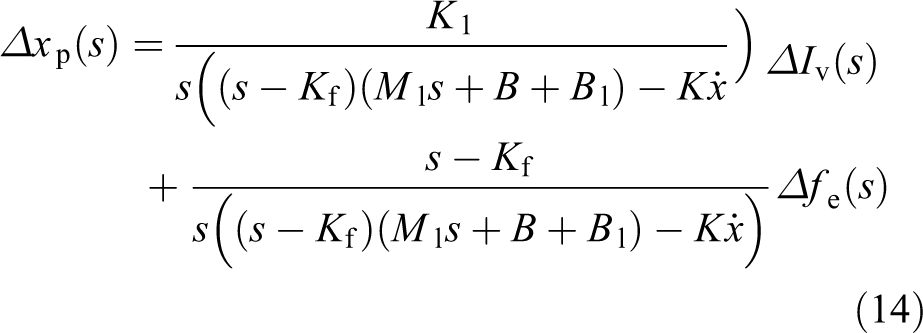

By eliminating

It can be seen that output force of the hydraulic actuator has relationship with the valve current, the velocity and acceleration of the hydraulic cylinder. We can separate the current Iv into two parts
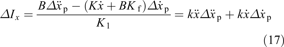
Then, the equation (16) can be simplified as
where
In this way, we could control the output force of the hydraulic actuator.

VMC of the leg
When it comes to active compliance, PD controller with floating-based inverse dynamics-based approach is usually adopted. 24 This method is not associated with force feedback, and it is hard to obtain precise information about the contact force as no contact sensor is installed at the foot of the SCalf-II. Although the joint torque can be measured by a joint force sensor and the foot force can be estimated, the problem of inaccuracy may cause unexpected kicking motions. 18 The VMC approach is used as the active compliance control strategy in this project as it needs no precise dynamic parameter. 25
Figure 5 shows the VMC approach used in the leg control of the SCalf-II. The inner loop implements the torque control detailed in the ‘Hydraulic actuator modelling’ section, and the outer loop is a position regulator. Pr is a vector
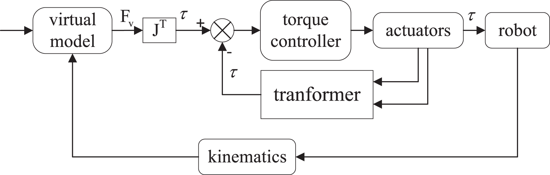
VMC schematic diagram. VMC: virtual model control.
In this approach, the virtual linear spring–damper components are placed at the end of foot in 3-D space, as shown in Figure 6. Each direction of the motion is tracked by a virtual force calculated by the model. The desired force can be established as

where

Virtual model of the quadruped robot leg.
Since the desired force at the end-effector workspace is obtained, Jacobian matrix is used to transpose it into the joint workspace, where the hydraulic actuator is controlled

where
Robot locomotion control
SLIP model-based locomotion approach is used to achieve robust motion control. Adaptive strategies to improve the dynamic abilities are detailed in this section. The locomotion approach proposed here is the upper layer controller of our three-layer control approach.
SLIP model of the locomotion control
To simplify the locomotion control, the quadruped robot is often equivalent to a hopping model shown in Figure 7. The control approach used here is based on Raibert’s three-part locomotion algorithm 12 : hopping control, speed control and posture control. The leg motion can be divided into two states: stance state and swing state. Footstep regulation is achieved in the swing state. Balance control of the torso is achieved in the stance state. The difference between the quadruped robot and hopping model is the hopping control. It is easy to control the step height of the quadruped robot as it has enough degree of freedom.
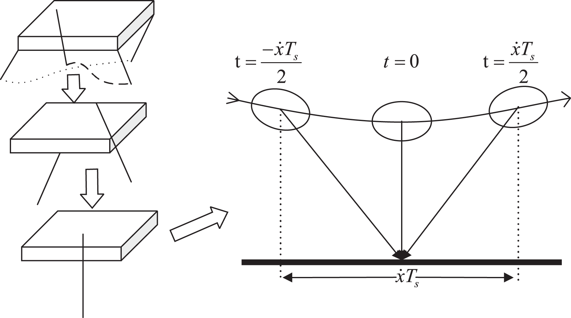
Simply SLIP model, the quadruped robot in trot gait can be seen as a biped robot and further a hopping robot, the motion of hopping model is shown on the right side. SLIP: spring loaded inverted pendulum.
Stance state control
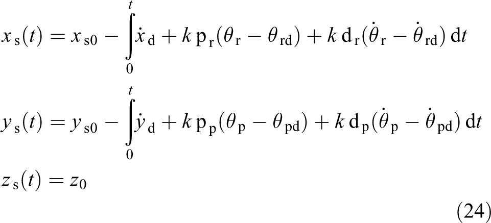
To keep the desired torso height, the leg in the stance state should maintain its length, which means the variation of the hip coordinates along z-axis is zero. Due to the compliant of the leg and the rhythm of periodic motion, the coordinate of the z-axis changes in a limited range, which means there are small differences in the length of the robot legs at different points in the stance state, as shown in Figure 7. Meanwhile, to keep the continuous motion speed, the motion along x-axis is a function of the starting point and the desired velocity

where
The torso orientation should be adjusted during the stance phase, where a PD section is used in the velocity control to maintain the torso orientation to the desired value. The introduction of

where
Swing state control
The foot trajectory in the swing state should be symmetrical in the hip coordinate when the robot is moving at a steady speed. To eliminate the gap in position and velocity between the swing and stance state, the new starting point
To have a smooth transition from swing state to stance state, which can reduce the impact force to the robot, the velocity along z-axis is set to zero at the time of lift-off

where
A set of fifth-order trajectory formulation is established to maintain these constraints

The trajectory is not constant in each period but a cluster line, which changes with different torso posture and motion desired targets, such as velocity and step height.
Trajectory map from single leg to quadruped robot
In our work, the quadruped robot moves in trot gait with a parameter

Trot gait map from single leg to the quadruped robot.
Omnidirectional motion control
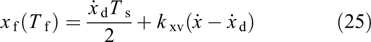
The robot can move along x-axis and y-axis based on the above trajectory without turning motion. We can achieve turning with a mixture of trajectories along x-axis and y-axis for they are decoupled. The turning motion is designed as the rotating along z axis. The desired coordinate of the robot leg with expected turning angular speed ω is
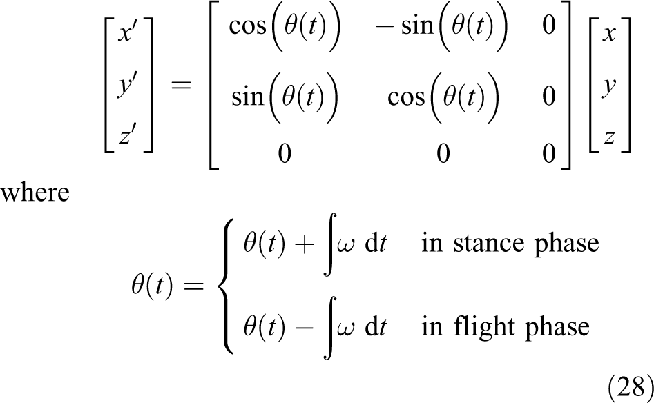
where x, y and z are the regulated trajectory detailed in the ‘SLIP model of the locomotion control’ section; x′, y′ and z′ are the adjusted trajectory for turning with angular speed ω.
Terrain adaptation strategies
Slope adaptation strategy
Without adjusting strategy, it is assumed that the desired torso angle is always same to terrain angle.

where

Torso adjusting strategy.
High stair adaptation strategy
In most cases, the robot can navigate on the general rugged terrain based on the active compliance. When facing big obstacles, such as high stair (over 10 cm), the corresponding gait adjusting strategy is needed. The variable stiffness and variable leg length (VSVL) control strategies are proposed to solve this problem. Firstly, in the swing state, the virtual spring stiffness of VMC is reduced to achieve soft collision. We try to adjust the spring stiffness in the swing period by a cosine function with the period of double stance state time, but the performance is good in simulation instead in the real system. A discount of the support phase stiffness is used as the swing phase stiffness. Secondly, foot collision detection is used to determine whether to touch the ground in advance or to delay the contact, which responds to large topographic mutations. When encountering this situation, the spring length of the VMC changes to the length at the collision time and sustains the length in the entire cycle. A state machine is used to recover the original parameters in a relatively large period such as 10 times of the gait period, which makes the robot back to normal state. This strategy has a great effect in simulation; however, collision detection cannot be realized in the current prototype as no sensors are installed at the foot of the SCalf-II. Currently, the SCalf-II is using the crawling gait to adapt to large obstacles.
Simulations and experiments
Simulations and experiments have been conducted to verify the proposed control approach. Most of adaptive strategies were carried out in simulation and the SCalf-II robot simultaneously. The joint torque control experiment was conducted on the single leg prototype to show the active compliance.
Simulations
In this work, the simulation is conducted in Webots, which is a development environment used to model, program and simulate mobile robots. The following simulation results are either obtained directly from Webots or plotted by Matlab with the logging date from Webots. The robot model in the simulation is shown in Figure 10, which is modelled with the same structure of SCalf-II.
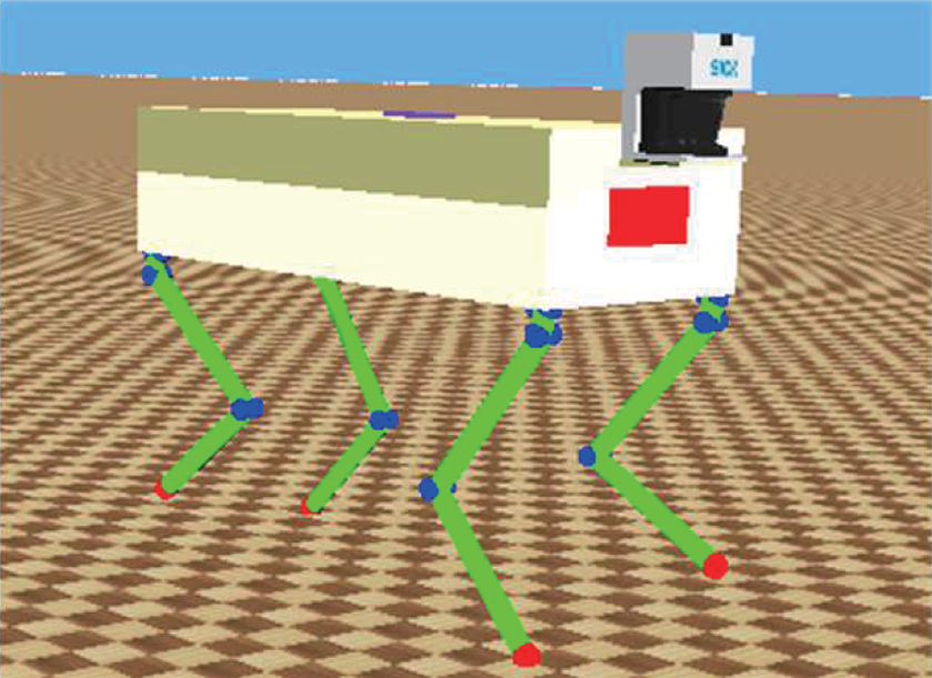
The quadruped robot model in the simulation software Webots.
Trotting motion simulations
The ability to move forward or sideward, make turns, accelerate and decelerate is essential for the quadruped robot to pass through complex terrains. A slalom involving all the basic motions is shown in Figure 11. All the motion commands mentioned above are given by the operator. The quadruped robot starts from the initial place and accelerates to 0.5 m/s with a rotation angular velocity of 0.2 rad/s. After the first column, the rotation angular velocity changes to −0.2 rad/s to round the second column. Lateral movement is chosen across the space between columns in returning path then back to initial place. The trajectory of the robot’s center of gravity (COG) during the slalom motion is shown in Figure 12. The start position is marked with an asterisk. In Figure 13, an acceleration and deceleration is shown by increasing the desired forward velocity (solid line) with a step of 0.1 m/s until 2 m/s and then decreasing to 0. The dashed line is the robot velocity in the simulation. The tracking result shows that the control method has a good acceleration and deceleration performance.

The robot slalom to show basic motion ability.

The trajectory of COG during slalom. Asterisk point indicates the starting COG. The robot walks through two rods through a motion with rotation and then returns through the forward and traverse movements. COG: centre of gravity.

Speed increasing from 0 to 2 m/s then reducing to 0.
Active compliance control of single leg
To evaluate the performance of active compliance using VMC, single leg dropping down simulation was carried out in Webots. The simulation model is shown on the right of Figure 14(a). Figure 14(b) shows the contact force of the single leg dropping down from 25 cm in vertical height. If the three sets of data are drawn at the same starting time, the impact peaks will be overlapped. To display the impact peak clearly, the three sets of data are plotted with a certain interval. The solid line is the contact force without compliance. The figure only shows the first impact as it touches the ground and then bounces back without compliance. The dotted line is the VMC simulation results the impact force is 3216 N, which is significantly reduced compared to the 5000 N without compliance. The simulation result proves that VMC can achieve good active compliance.

Simulation and experiment of the single leg drop-down, the leg is about 30 kg in total weight, we set the toe position of
Lateral impact recovery
Recovery from unexpected perturbations can verify the robust ability of the control approach. Due to the morphology of the quadruped robot, it is hard for the robot to balance along the coronal plane, which means the roll angle of the quadruped robot. In the simulation, a pendulum bob was used to exert an unexpected impact. The impulse acted on the robot was 135.55 kg·m/s, and the recovery process is shown in Figure 15. The robot has a 0.185 rad tilt in the torso roll angle when encountering the push power and successfully recovers from the perturbation quickly. The test proves that the locomotion control approach has strong robustness against external disturbances.

Velocity and posture of the robot during lateral impact recovery.
Up and down the stair
This section shows the robot going up and down the 15 cm stair using the VSVL control methods. The virtual spring stiffness of VMC is 50,000 Nm in the stance state and 25,000 Nm in the swing state. The leg length variable is shown in Figure 16 during this process. RF leg first steps on the stair and then keeps the leg length at the current moment. Then the LF leg steps on the stair and the length variable is about the stair height. At the same time, both hind legs vary their lengths in the opposite direction to keep the torso posture. The state machine has been adjusting the length of each leg to restore the target height during this time. After 20 s, the robot steps down the stair, and all the lengths of the legs need to be increased to maintain the stability of the body

Leg length variable during up and down 15 cm stairs.
Slope adaptation
The max slope the robot can get through can be used to demonstrate the robot
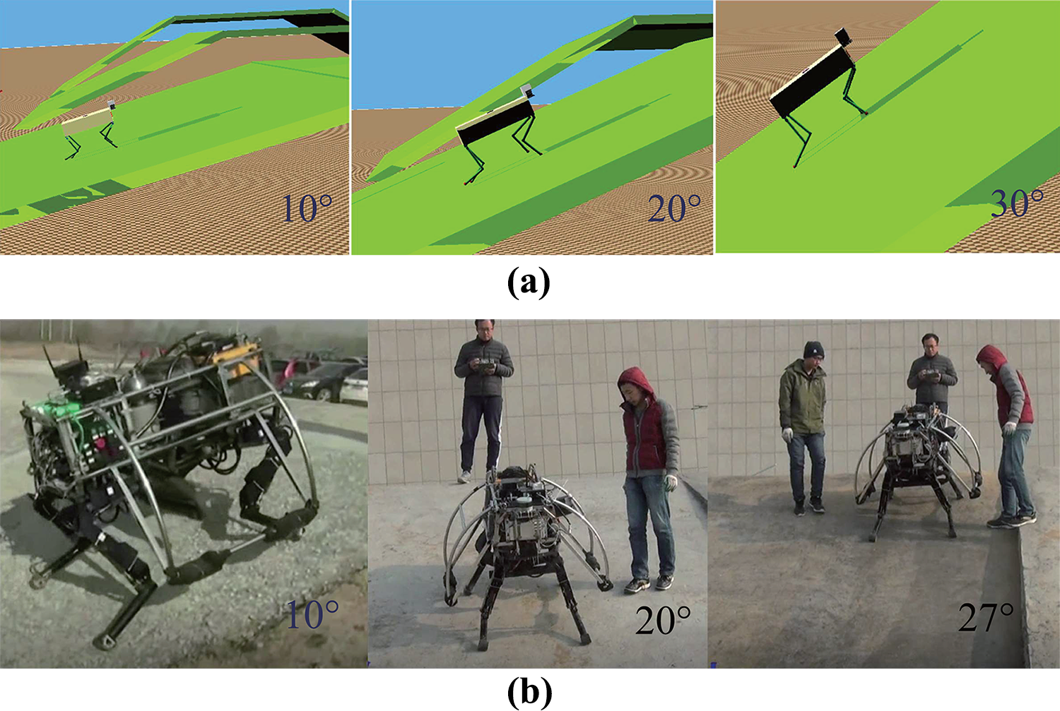
Climbing slope experiments, the slope is 10°, 20°, 30° ((a) climbing slope in simulation) from left to right in simulation and 10°, 20°, 27° ((b) climbing slope in experiments) for SCalf-II, as 27° is the max slope succeed for the SCalf-II prototype.
Experiments
For the SCalf-II, the main system is controlled by a PCM-3362 board (Advantech) running real-time patched QNX, which is a Unix-like real-time operating system. Controller area network (CAN) bus is used to communicate the main system with a power controller, which receives the command of the power signal and returns operation condition information. The analogy signals about position, and force sensors are collected by a 12-bit DAS module PCM-3718 at 250 Hz. The torso posture is measured by the VG440 module at 100 Hz. Valves are controlled by a 12-bit analog output module Ruby-MM-1612 with voltage-controlled current source circuit. All the experiments’ results shown below are based on these control hardware.
Table 2 compares different quadrupeds robots’ control system configurations with the SCalf-II. The BigDog (Boston Dynamic Company, Boston, USA) is a hydraulically driven quadruped robot, the HyQ (Italian Institute of Technology, Genoa, Italy) is an electro-hydraulic driven quadruped robot and the MIT Cheetah (MIT) is an electric motor driven quadruped robot. By comparing the actuator response frequency, servo control frequency and IMU acquisition frequency, it shows that Scalf-II robot can obtain good motion control effect with lower performance hardware, which saves cost and reflects the robustness of the proposed control method.
Different robot control system configurations.

Joint torque tracking experiments
Joint torque control is the fundamental servo control of the robot motion, which decides the effect of upper layer control performance. A series of joint torque tracking experiments on our robot in different tracking frequency from 0.5 Hz to 1.5 Hz were carried out as shown in Figure 18. A sinusoid signal with an amplitude of 10 Nm is the desired torque, shown as the dashed line. The hydraulic actuator output shown in solid line, which proves that the hydraulic actuator model we established in the ‘Hydraulic actuator modelling’ section has a good torque tracking ability.

Torque tracking experiments: (a) torque tracking of 0.5 Hz sine signal and (b) torque tracking of 1.5 Hz sine signal.
Active compliance experiments
On our single-leg platform, the same dropping down experiment as in the simulation was carried out. As shown in Figure 14(b), prototype experiments in dash line show that the impact is 3600 N, which is not as good as the simulation result (dot line) because of the limitation of the valve bandwidth and dynamics of the hydraulic cylinder. But the impact is significantly reduced compared to the no-active compliance control. This proves that using VMC can achieve a good compliant effect on the actual system.
The active compliance of the SCalf-II prototype was proved by the following experiments. The robot went through a general uneven terrain (fluctuation is less than 5 cm) using the position control without compliance and active compliance control, respectively. The effect of active compliance on the SCalf-II is shown by comparing torso posture and acceleration. As shown in Figure 19, pitch angle variable is over 0.13 rad without active compliance and limited in 0.08 rad using the VMC. The results verify that the VMC enables the robot with smaller fluctuations during rough terrain, which means active compliance improves the robot adaptive ability to complex terrains.
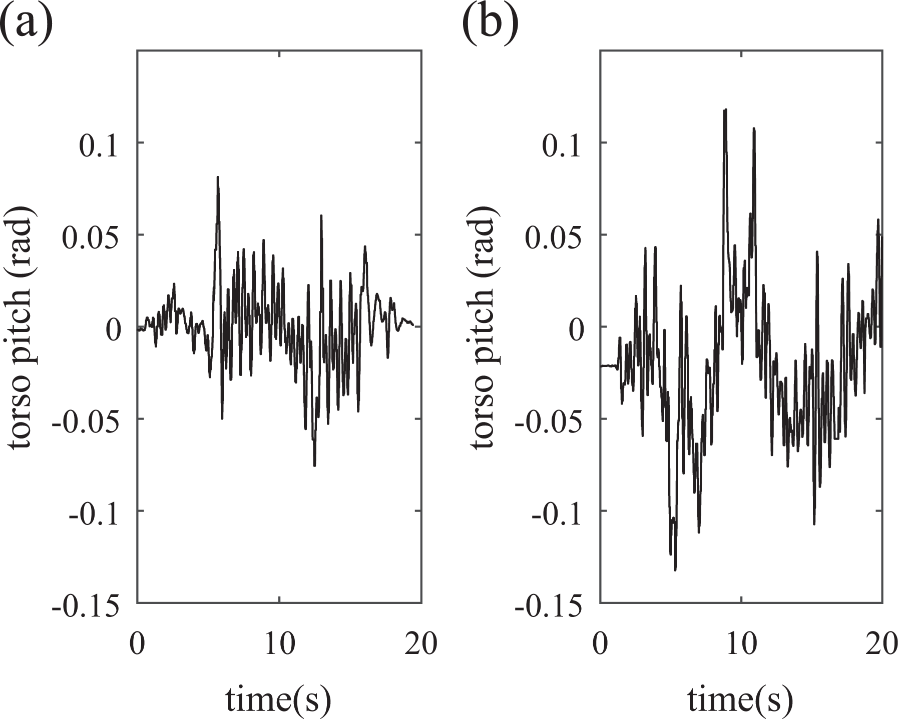
Torso pitch angle variation through uneven terrain (a) using VMC as active compliance and (b) position control without compliance. VMC: virtual model control.
Push recovery
The quadruped robot in the dynamic gait has only two or less than two legs in the support phase at a time. In the dynamic gait, there is no static stability, which requires at least three legs in the support phase. The stability of a quadruped robot is evaluated by the balance performance of the robot in dynamic gait. As detailed in the ‘Lateral impact recovery’ section, the quadruped robot is more difficult to maintain balance due to its topology. Artificially applying lateral thrust to detect the balance recovery ability of the robot is an effective way to test the robustness of the robot motion control algorithm.
For the SCalf-II, a push impact was exerted by a person on the broadside of the robot, as shown in Figure 20. The push recovery in the experiment has the same result as in the simulation. The experimental result of torso posture and adjusting speed during the push recovery is shown in Figure 21. The roll angle is 0.2618 rad pushed by human and after 5 s, the robot returns to stable state. As the robot movement and the response speed of the actuator are limited by the valve bandwidth, the robot’s adjustment process is about twice as long as that in the simulation. However, the ability of recovery from unexpected impact makes the robot robust to go through complex terrains.

Push recovery process in the quadruped robot prototype.

SCalf-II push recovery experiment results.
Climbing slopes
Same as the test in the simulation, the climbing ability of the SCalf-II was tested by a series of slopes in increasing gradient from 10° to 27° as shown in Figure 17(b). The robot perceives information about the terrain by the position of the feet and torso orientation collected by the IMU(VG44). The max slope succeeded by the SCalf-II was about 27° as the robot cannot get enough friction force on the foot surface to avoid sliding on more gradient slopes. The climbing slope ability can be influenced by the ground property, which means the robot can perform better at greater friction and harder ground.
Discussion
This section summarizes the locomotion algorithms used on the SCalf series of robots to illustrate the advantages of the proposed control method in terms of motion performance.
A COG trajectory planning method for the SCalf robot to travel on rough terrain is proposed by Shuaishuai et al. 29 Stable motion of the robot in static gait is achieved by the planning of COG trajectory, but the robot cannot achieve good dynamic performance.
To improve the dynamic motion capability of the SCalf robot, a locomotion algorithm based on full-scale virtual model is proposed by Guoteng et al. 30 The effectiveness and robustness of the proposed method are verified by dynamic simulation. However, the high-bandwidth servo actuator and high precision sensors required by this control method constrain its application on the physical platform.
A controller designed for the LittleCalf to achieve dynamic locomotion is proposed by Guoteng et al. 31 The LittleCalf is a scaled down version of the SCalf robot used to verify the control algorithm before applying to the SCalf robots. The controller takes the torso attitude angles and velocities into planning foot trajectories and enabled the robot to have a wide range of trotting gaits and omnidirectional motions. However, this control algorithm is based on position control. It does not consider the interaction force between the foot and the ground. The large grounding force will cause damage to the linkage and actuators of the robot in physical platform.
The locomotion algorithm proposed in this article deals with the constraints of physical platform and dynamic motion requirements. The proposed active compliance control method can reduce the interaction force between the foot and the ground to protect the robot body. The gait control method based on SLIP model realizes the dynamic motion capability of the robot and, at the same time, makes adaptive adjustment for external disturbances. This control method achieves good motion performance of the robot under the condition of constrained physical platform, which benefits the engineering realization of the robot.
Conclusions
A motion control approach with active compliance for hydraulic actuated quadrupeds was proposed in this work. The model of the valve-controlled hydraulic actuator was first established and linearized to obtain the servo control principle. To achieve active compliance of the leg, the virtual spring–damper model was placed at the foot end in 3-D space to get the virtual force. The torso posture and desired motion targets were adopted to design the trajectory regulator. To improve the adaptability to different terrains, control strategies were proposed for decoupled whole direction movements, climbing slopes and stairs. Both the simulations and experiments verified the effect of the compliance especially in dealing with impact forces. At the same time, the robot was stable enough to pass through complex terrain and recover from lateral impact quickly.
The control approach proposed in this work provides some guidances on the following aspects. Although many literature introduce compliance, most of them are for electric motors. The modelling process for torque control of the hydraulic actuators is rarely introduced. In this work, the VMC approach performs a good compliance which spares us from the complicated dynamics modelling. Self-adjusting locomotion control based on dynamic gait is an important way to improve stability of the quadruped robot. All these aspects are essential for the hydraulic actuated robot to achieve robust control.
Footnotes
Declaration of conflicting interests
The author(s) declared no potential conflicts of interest with respect to the research, authorship, and/or publication of this article.
Funding
The author(s) disclosed receipt of following financial support for the research, authorship, and/or publication of this article: This work was supported in part by the National Natural Science Foundation of China [Grant No. U1613223, 61603216], and in part by the National High Technology Research and Development Program of China [Grant No. 2015AA042201]. Lelai Zhou acknowledges the support by the Young Scholars Program of Shandong University (YSPSDU).