
Abstract
Robots have increasingly become integral in enhancing human life, with growing demands for robots with high payload-to-weight ratios and dynamic capabilities like running and jumping. Hydraulic actuation, renowned for its high power-to-weight ratio, is a critical enabler of these capabilities. However, its effectiveness depends significantly on the specific architecture employed. This review systematically examines centralized hydraulic power units (cHPUs) and electro-hydraulic actuators (EHAs) in legged robots, specifically quadrupeds, hexapods, and monopods, focusing on power density, weight, joint power distribution, and application suitability. Following PRISMA guidelines, we analyzed over 35 hydraulic-legged robots from 70+ articles, finding that while cHPUs offer greater power, their efficiency is reduced by the weight and leakage of components like valves and hoses. In contrast, EHAs demonstrated a superior power-to-weight ratio due to their self-contained, hoseless design. Our analysis suggests that cHPUs are better suited for a few closely positioned joints, while EHAs for powering multiple joints over larger distances. Based on empirical data from manufactured robots, this research highlights EHAs’ advantages in power density optimization. It recommends future studies explore additional metrics like power-to-volume ratios and cost-effectiveness to refine hydraulic architecture selection for robotic systems.
Introduction
The advent of robotic systems has significantly transformed various aspects of human life, from automating industrial processes to revolutionizing healthcare, natural sciences, and academia. 1 These systems have become increasingly prevalent and influential in daily life.2,3 A key player in this revolution is mobile robots, which, unlike fixed-base or gantry robots, are designed to move freely within their surroundings, making them highly versatile for various applications. 4 Mobile robots can be equipped with either wheels or legs. Wheeled robots offer rapid movement on flat surfaces while maintaining balance, especially when equipped with multiple wheels.5,6 However, they are less efficient on rough or uneven terrain. Legged robots, on the other hand, achieve dynamic locomotion similar to animals, allowing them to overcome significant obstacles and traverse challenging environments. This capability makes them ideal for tasks that are too dangerous or difficult for humans, such as planetary exploration, disaster relief, and defense operations.7–12
In designing legged robots, the power source or actuation system is a crucial aspect that determines their mechanical design, complexity, and ability to perform intended functions. 13 Legged robots can be classified according to their actuation systems into electric 14 and fluid power systems, which include pneumatic 15 and hydraulic. 16 Understanding these classifications is essential for grasping the different types of legged robots and their capabilities. Electric actuators employ various techniques to convert electrical energy to mechanical form. 17 They are widely used in robotics due to their ease of control, cost-effectiveness, suitability for low-power operations, and compactness. 18 Examples of popular legged robots that are electrically actuated include MIT Cheetah, 19 ANYmal, 20 and Stanford Doggo. 21 However, this type of actuation has its drawbacks. Typically, these actuators are sized for the maximum required torque even if they would not operate at that level. 22 In addition, they suffer from magnetic saturation and high heat dissipation, they also consume a lot of energy at zero speed. Furthermore, electric actuators are typically combined with mechanical gear reduction devices, which increase their output torque and decrease rotation speed. However, this addition also increases friction and reduces the compactness of the actuator. 23 Pneumatic actuation, a form of fluid power actuation: converts the power of the fluid (air) to mechanical form. So far, they have found applications in Bionic Kangaroo, 24 exoskeletons, 25 rehabilitation robotics, 26 robotic legs. 27 However, they suffer from low efficiency, poor control performance due to compressibility, and high noise, making them difficult to use in mobile robots. 28 Hybrid actuators in robotics combine different actuation principles to enhance performance, flexibility, and adaptability. The most common type is the combination of pneumatic and electric actuators. This combination was used by Heya et al. in 2023 to develop a two-degree-of-freedom hybrid actuator. This innovative integration produced a torque output four times greater than that of conventional designs of similar size, significantly helping to miniaturize robotic systems. 29
Hydraulic actuation method, which took its name from “Hydro,” the Greek word for water, is another form of fluid power actuation that utilizes liquids to transmit and amplify force.18,30 Hydraulic technology existed during ancient times, beginning long before the second century BC among the Greeks, Romans, and Egyptians. The documented history indicates that the first hydraulic engineering, which used water as a fluid, was used by these three. The Greeks developed the aqueduct on the Greek island of Samos, constructed by the notable hydraulic engineer Eupalinus of Megara. The Egyptians used it to develop irrigation systems for agriculture, while the Romans used it to develop water supply systems.31,32 Hydraulic actuation systems operate mainly based on Pascal’s law, which states that the pressure exerted on a confined fluid is transmitted uniformly in all directions, assuming negligible gravitational effects. Typically, hydraulic systems feature a hydraulic pump for pressurizing the fluid, hydraulic lines (comprising tubes, hoses, and flexible pipes) for fluid transportation, valves facilitating diverse control actions, and hydraulic actuators (linear or rotary) which convert fluid power into mechanical power.33,34
During the mid-1900s, specifically between the 1950s and early 1960s, hydraulics, which was the leading actuation method was first employed in robotics to create the world’s premier industrial robots, Versatran 35 and Unimate. 36 Furthermore, the late 1960s saw the introduction of the GE walking truck, 37 followed by Raibert’s monopod and quadruped. 12 Although this actuation is rooted in history, it lost popularity in the mid-1980s when earth magnetic and brushless motors were introduced. 18
Many applications switched to electric drives because of their ease of use as well as the leakage issues and bulkiness associated with hydraulic systems during that period. However, Figure 1 shows that hydraulic actuators remain an outperformer of pneumatic and electric actuators in terms of stress (relation between the acting force and the cross-sectional area) and strain (relative deformation due to external force) exhibiting significantly higher maximum stress and strain values, indicating their ability to handle high forces and pressures. 38 In addition, hydraulic systems still retain their superiority in terms of power-to-weight ratio compared to other systems, a characteristic that is crucial for the development of dynamic robots. 39 These inherent advantages of hydraulics brought it back to the hot region of research, although with numerous research focused on making it leak-free and portable; areas where hydraulics traditionally falls short in comparison to other actuation methods. This resurgence is highlighted in Figure 2, which presents the annual number of publications on hydraulic-legged robots based on the database compiled in this review. This chart illustrates a significant increase in the use of hydraulic systems in legged robots over the past two decades, with the most notable being a 1200% surge from 2000 to 2015. These legged robots have used hydraulics to deliver powerful and dynamic motion while reducing their overall weight and size, which is important for their ability to move around.


Publications on hydraulic-legged robots over the years, indicating a significant rise of 800% in the last two decades based on the database compiled in this study.
In light of these developments in hydraulic legged robots, many researchers have shed light on various themes of legged robots through review articles. In 2006, Machado and Silva 41 provided one of the earliest reviews of legged locomotion, emphasizing the pressing need for improved actuation systems. Zhuang et al. 42 reviewed heavy-duty legged robots characterized by a high body mass to payload ratio, focusing on their mechanical structures, force distribution strategies, control methodologies, and power source considerations. One of their key propositions was to improve the energy efficiency of power units. Suzumori and Faudzi 18 reviewed hydraulic trends in robust-legged robotics applications, reporting on how different researchers have developed hydraulic components and robots in general. Carpentier and Wieber 43 reported on recent progress in locomotion control, while Gao et al. 44 reviewed the progress and challenges in multi-legged robots. Gong et al. 45 investigated the object manipulation abilities of existing legged robots.
Although there have been many reviews regarding hydraulically actuated-legged robots, there is currently a lack of in-depth exploration of the performance of the power units characterized by varying architectures and components in these robots. Meanwhile, it is crucial to understand how each design choice influences the performance of the hydraulic power unit (HPU) which can constitute up to 40% of the robot’s total mass and directly affect factors such as energy efficiency, noise levels, weight, cost, and the amount of heat produced, all of which impact the robot’s ability to perform its intended tasks effectively. Therefore, this systematic review aimed to address these qualitative and quantitative questions with a focus on quadrupeds, hexapods, and monopods:
What are the key criteria for evaluating an HPU?
How does the type of HPU architecture impact the robot’s performance metrics, such as power density, efficiency, and weight?
In which scenario should centralized or decentralized architectures be considered, and how do they compare when evaluated on an even playing field?
To address these questions, we conducted a state-of-the-art analysis of existing manufactured hydraulic quadrupeds, hexapods, and monopods, focusing on their mechanical structures, degrees of freedom (DOFs), capabilities, and HPUs. We then performed an architecture-based comparison of mounted and unmounted HPUs across 30 hydraulic-legged robots to identify performance criteria for centralized and decentralized architectures. To ensure a fair comparison, we leveled the evaluation between the two architectures and assessed them against the established performance criteria, highlighting their respective strengths and weaknesses.
The remainder of this article is organized as follows. Section “Research methodology and selection criteria” outlines our database curation methodology and selection criteria. In Section “State-of-the-art of hydraulic legged robots in different regions,” we present a region-based state-of-the-art of hydraulic quadrupeds, hexapods, and monopods. Section “HPU architecture-oriented analysis” offers an architecture-based analysis of HPUs. Section “Discussion” provides a comparative assessment of the two HPU architectures, highlighting key findings. Finally, Section “Conclusion” concludes the paper and discusses potential avenues for future research.
Research methodology and selection criteria
A comprehensive survey of hydraulic-legged robots was conducted for our database. To ensure transparency in our research, the preferred reporting items for systematic reviews and meta-analysis (PRISMA) statement guidelines for systematic reviews were adopted. 46 Database search included IEEE Xplore, Google Scholar, and Scopus, using specific queries without any restrictions on publication year to encompass all hydraulic-legged robots documented in the literature:
In IEEE Xplore, we searched in document titles using the Command Search tool with the following keywords: “Legged Robots,”“Quadruped Robot,”“Hexapod Robot,”“Hydraulic Actuation,”“Hydraulic Hexapod,”“Hydraulic Monopod,” and “Hydraulic Robot.”
For Google Scholar and Scopus, we used the “Publish or Perish” tool, 47 a bibliometric software that extracts a database of academic articles based on input keywords. The same keywords above were used to search in titles and abstracts.
Throughout the search process, a total of 2393 articles were gathered, these articles include 929 from IEEE Xplore, 990 from Google Scholar, and 474 from Scopus. A citation search of robust review articles also helped identify 46 other articles. Out of the 2439 articles, a stepwise screening process was carried out as shown in Figure 3. At the final step of the article screening process, the following criteria were defined:
The article must be based on a physical robot (quadruped, hexapod, and monopod), or a physical HPU, or an electro-hydraulic actuator (mounted or unmounted).
Main parameters of the robot/HPU must be available in the literature.
The article must be written in English or French.
The article must not be a review article.
These criteria were applied to 139 eligible articles, resulting in 74 articles being included. These articles covered 39 robots, 1 unmounted HPU, 5 mounted, and 4 unmounted EHAs.

PRISMA flow diagram illustrating the step-by-step process used to compile the final reference database for hydraulic legged robots. 46
State-of-the-art of hydraulic legged robots in different regions
Hydraulic-legged robots come in various configurations depending on their intended applications. In our research, we focused monopods, quadrupeds, and hexapods, their distribution shown in Figure 4 indicated quadrupeds to be the most common.

Distribution of robot types that are included in this review.
Early legged robots
Hydraulics has a long history, but its use in robotics began in the late 1900s, the early hydraulic legged robots made before the 21st century are shown in Table 1 and Figure 5. The first of them is the GE walking truck (Figure 5(a)) developed by Mosher in collaboration with General Electric Corporation in 1965. 48 The quadruped robot had an offboard pump and weighed 1360 kg. It was not designed to be autonomous hence, operated by a person seated in a dedicated compartment.
Early legged robots from the 20th century.

First author’s name attributed to robot. Year refers to development date; citation year in references.

Raibert et al. at the Leg Labs at Carnegie Mellon University, and later, Massachusetts Institute of Technology, developed a few hydraulic robots between 1979 and 1987. In 1979, Raibert built his first hopping robot, a computer-controlled pogstick (Figure 5(b)). The first planar monopod was later improved and resulted in a 3D hopper. This robot was able to hop in place and travel from point to point. He subsequently built a biped and quadruped robot. The quadruped robot (Figure 5(c)) measured 1.05 m × 0.35 m × 0.95 m (L × W × H) in dimension and had each of its legs with 3 degrees of freedom. The robot weighed 25.2 kg and was powered by an off-board pump.12,49 The Adaptive Suspension Vehicle (Figure 5(d)) was developed and tested by Kenneth J. Waldron at Ohio University between 1982 and 1987. The hexapod robot had 18 degrees of freedom, 3 on each leg. The giant robot, which had its actuators operate at a maximum pressure of 138 bars, had an onboard pump and weighed approximately 3200 kg. It was operated by a person who sat in the robot’s cockpit. The robot had six operating modes, providing the operator with a range of options to use depending on the terrain to be traversed and the task to be performed. 51 Toward the end of the 20th century, Plustech in Finland developed a hexapod called the Plustech walking machine (PWM; Figure 5(e)), which weighed 3400 kg. It had 3 degrees of freedom per leg and was 7.4 m × 2.7 m × 3.7 m in dimensions. 52
21st century legged robots
During the 21st century, especially in the American, Asian, and European continents, the use of hydraulics in legged robots has received significant research attention. As shown in the distribution chart in Figure 6, several continents have been the main contributors to the development of new hydraulic robots in the 21st century.

Schematic representation of the different countries and continents with the number of robots developed and their share in the total number of hydraulic legged robots in the 21st century included in this review (based on the database compiled in this study).
America
Table 2 and Figure 7 show the America-based Legged Robots. To the best of our knowledge, Boston Dynamics developed seven of the eight hydraulic-legged robots based American continent. They started with a quadruped robot named BigDog that had versions in 2004 (Figure 7(a)), 53 2006 (Figure 7(b)), and 2008 (Figure 7(c)). The 2004 version funded by the US military’s Defense Advanced Research Projects Agency (DARPA), represented a significant breakthrough in hydraulic robotics. BigDog 2004 53 was 1 m tall, 1 m long, 0.3 m wide, and weighed 90 kg with all systems onboard. Its four legs had four degrees of freedom (DOFs) each, although only three were active. The robot was operated at a pressure of 206.8 bars and had a payload capacity of 50 kg.
America-based legged robots included in the review.

N/A: not available; W: wheeled; D/HD: DOFs/Hydraulic DOFs.
Year of citation used. **First Author’s name was attributed to robot. ***Inferred from robot’s picture and video.

There was not much difference between BigDog 2004 and 2006 versions, except that the configuration of the legs that all faced the forward “〉〉” direction was changed to a “forward-backward 〉〈” configuration. Semini stated that this change was probably due to stability problems. 60 BigDog 2008 (Figure 7(c)) had more capabilities and improvements than the earlier versions. The major difference is the new kinematic structure of the robot leg, where an additional active rotational joint was added, making the active degrees of freedom sum up to 16. The robot was 1 m tall, 1.1 m long, 0.3 m wide, and weighed 109 kg with all systems onboard. The robot remarkably had a payload capacity of 150 kg. 56 Boston Dynamics also developed robots such as Spot (Figure 7(e)), LS3 (Figure 7(d)), and WildCat (Figure 7(h)). However, detailed information about Boston Dynamics robots are not readily accessible.
Furthermore, in 2006, Yobotics, Inc., Cincinnati, and the Florida Institute for Human and Machine Cognition collaborated to produce a 2 DOF planar monopod that was not named, hence we called it by the name of the first author of its article (Krupp’s Monopod (Figure 7(f))). 55 The monopod, which operated at 206.8 bars, weighed 57 kg with all systems onboard.
Although the USA made significant contributions, the Defense Research and Development Institute of Canada developed the first and only Hydraulic Wheeled Quadruped Robot in the USA and Canada called the Micro-Hydraulic Toolkit (MHT (Figure 7(g))). MHT weighed 150 kg with all its systems onboard and was operated at 172 bars pressure. It had 3 DOFs per leg with electric motors driving the wheels, which required less torque, while the other two DOFs that required high torques were powered by hydraulic actuators.58,59
Asia
China has enormously contributed to this research area in Asia in this century. It was reported that since 2011, the country has been investing in a well-funded project to develop a Chinese equivalent of BigDog. 61 Table 3 and Figure 8 showcase the hydraulically actuated robots developed in China during the 21st century.
The China-based legged robots included in the review.

N/A: not available; D/HD: DOFs/Hydraulic DOFs; W: wheeled legged; Year: year of development.
Year of citation used.

Shandong University developed three versions of a quadruped that were named Scalf, to transport load on tough terrain. Scalf-I (Figure 8(a)) was developed with three active degrees of freedom per leg and had 1 m × 0.4 m × 0.68 m dimensions. It weighed 65 kg without a hydraulic power pack, operated at 210 bar pressure and had a maximum payload capacity of 80 kg. The developers stated it ran at a velocity of 1.8 m/s with trot gait on flat ground during experiments. 62 Scalf II (Figure 8(e)), which weighed 120 kg, was developed to have an onboard power unit that operated at 190 bars. The robot had 3 DOF per leg and was 1.1 m long, 0.45 m wide, and 1.1 m high with fully extended legs.70,71 In 2017, Scalf-III (Figure 8(f)) was developed, and one of the major differences was that they changed the “forward-backward 〉〈” configuration of the legs of Scalf-II to “backward-forward 〈〉” configuration because the shank of Scalf-II touched the ground during squatting motion. Scalf-III retained the 3 DOF per leg and weighed 200 kg with an onboard hydraulic power unit operated at 210 bars. This robot, developed to transport payloads in tough terrains, could withstand a payload of 130 kg during experiments. 72
Another quadruped robot named the Baby Elephant, developed as a mechanical carrier, was created by a team of researchers at Shanghai Jiao Tong University with a total weight of 130 kg. It was stated to have a payload capacity of more than 50 kg. Baby Elephant (Figure 8(b)) was about 1 m tall, 1.2 m long, and 0.5 m wide; it had 12 DOFs in total, 3 DOFs per leg. The novelty of the Baby Elephant is the use of an electric motor to control the flow to the actuators instead of valves; they stated that they were able to reduce the leakage of the system by 90% compared to a servo-valve controlled system.59,63–65 The Beijing Institute of Technology (BIT) also developed a quadruped (Figure 8(c)) that was 1.2 m long, 0.4 m tall, and 1 m tall. The robot weighed 120 kg with all systems on board and had 16 DOFs. 67 The NUDT quadruped (Figure 8(d)) was developed at the National University of Defense Technology and weighed 100 kg with all systems on board. It was 1.2 m long, 0.55 m wide, and stood 1 m high. The robot was operated at a pressure of 210 bars.68,69
The State Key Laboratory of Fluid Power and Mechatronic Systems, Zhejiang University and its affiliated institutes have also been particularly active in this domain, producing several distinctive platforms. Their robot, which featured first in a publication, is WLBOT (Figure 8(i)), a 220 kg quadruped wheeled–legged robot (1.1 m × 0.72 m × 1.0 m) with 8 active DOFs and 2 passive wheels, was capable of carrying 50 kg. 75 Furthermore, in 2022, they released a hydraulic hexapod named ZJUHEX01 (Figure 8(j)), dimensioned at 1.6 m × 1.1 m × 1.5 m with 18 active DOFs (3 per leg). The robot originally weighed 1100 kg with a 200 kg payload, later reduced to 800 kg with an increased payload of 300 kg. During experiments, it achieved a locomotion speed of 0.375 m/s.76–78 More recently, they introduced Spurlos (Figure 8(l)), a lightweight quadruped employing fiber-reinforced polymer actuators and a mortise-and-tenon composite torso with the aim of reducing the bulkiness in hydraulic robots. They achieved a weight of 58.9 kg with an onboard HPU, supported an 80 kg payload, and measured 1.044 m × 0.54 m × 0.981 m with 12 DOFs (3 per leg). It demonstrated squat and trot motions in experiments at 100 bar, though its maximum operating pressure was 210 bar.79,80
The Harbin Institute of Technology has also developed multiple hydraulic robots. One is MBBOT (Figure 8(g)), a quadruped with 20 DOFs (5 per leg), of which 16 are active. With all power elements and additional payload onboard, MBBOT weighed 200 kg and achieved a trotting speed of 0.83 m/s during experiments. 66 Another, developed in collaboration with the Shenzhen Academy of Aerospace Technology, is EHbot (Figure 8(h)), a quadruped with 12 DOFs (3 per leg), standing 0.7 m tall and weighing 140 kg with an onboard HPU.73,74 In addition, Harbin partnered with Zhejiang University to create WLR-IV (Figure 8(k)), a hydraulic single wheel–legged robot motivated by the need for lightweight and integrated manufacturing methods. It weighed 7.5 kg and integrated a custom micro HPU (210 bars) with a plunger pump and accumulator, providing compact high-pressure actuation through a hose-less hip joint. WLR-IV had 3 active DOFs (hip, knee, and wheel drive), with the wheel driven by a geared DC motor and the other joints hydraulically actuated. 81
Another Asian country with a significant amount of ongoing research and development in Hydraulic Legged Robots in the 21st century is Japan, as shown in Table 4 and Figure 9. Kenken Monopod (Figure 9(a))82,83 is a robot from early this century. Hyon et al. at Tohoku University developed a monopod in 1999, although references were not made available until 2002. The monopod had two active joints actuated by hydraulic cylinders. The robot, which had an off-board power supply and a weight of 13.26 kg, achieved high-speed hopping. Titan XI (Figure 9(b)),84,85 a 6800 kg quadruped robot which had all of its systems on-board was developed at the Hirose Lab of the Tokyo Institute of Technology. It had 3 DOF on each leg and was uniquely designed for construction work on slopes.
The Japan and Korea based legged robots included in the review.
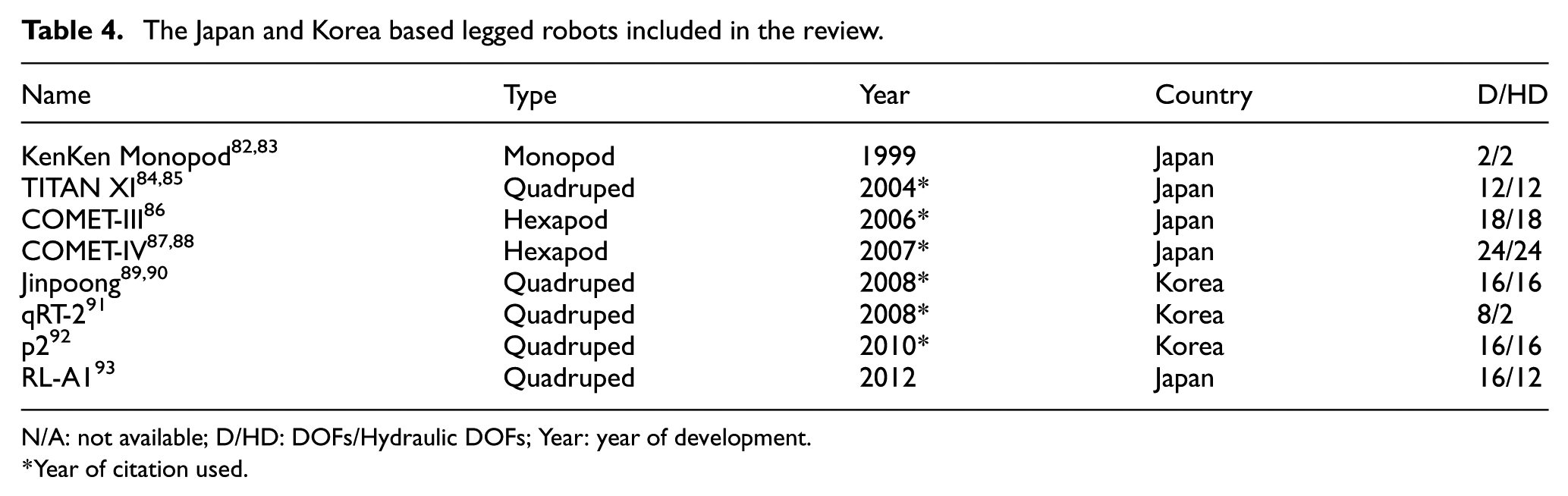
N/A: not available; D/HD: DOFs/Hydraulic DOFs; Year: year of development.
Year of citation used.

The Chiba University Operating Mine Detection Electronics Tools (COMET) was developed for application to a wide range of daunting tasks, including detecting landmines and performing rescues in disaster areas. COMET was created in four different versions: COMET-I, COMET-II, COMET-III, and COMET-IV, although to the extent of the authors’ knowledge, only the latter two had descriptions available to the public. 94 The COMET-III (Figure 9(c)), dimensioned as 1.6 m × 2.6 m × 1.0 m, was a hexapod with 3 degrees of freedom per leg. It weighed 1200 kg with all systems on board, had 300 kg payload capacity, and had an operating pressure of 140 bars. 86 COMET-IV (Figure 9(f)) was developed to improve version III; It was dimensioned to be 2.8 m × 3.3 m × 2.5 m, had 4 DOF per leg instead, and weighed 2200 kg, with all systems on board. It was equipped to have more power output and was able to walk faster than the previous version.87,88
Another Japanese robot, Ritsumeikan Leg, Animal Type 1 (RL-A1 (Figure 9(e))), which is a quadruped entered the development phase. The robot, which had the dimensions of 1 m × 0.67 m × 1.024 m, had an on-board power unit and weighed 113.8 kg. It had 4 degrees of freedom per leg, although only three were active. 93
In Korea, specifically at the Korea Institute of Industrial Technology (KITECH), several hydraulically actuated quadrupeds were developed. One of the earliest robots was p2 (Figure 9(h)), which took a distinctive approach from the common way of using hydraulic cylinders for actuation. This platform was fully actuated with hydraulic motors instead, providing 16 active degrees of freedom, and was dimensioned at 1.0 m × 0.4 m × 1.2 m. 92 Furthermore, they also produced qRT-2 (Figure 9(g)), a hybrid quadruped robot combining two legs and two wheels. In this design, the two front legs each had three active DOFs, while the hind legs were equipped with passive wheels. qRT-2 measured 1.0 m × 0.5 m × 1.0 m, weighed 60 kg with an off-board power supply, and was capable of carrying up to 40 kg. During experiments, it achieved a maximum velocity of 1.5 m/s. 91
Another major contribution from KITECH was Jinpoong (Figure 9(d)), a quadruped robot designed for load carrying over rough terrain. Jinpoong weighed 120 kg with all systems onboard, had 4 DOFs per leg (16 in total), and supported a payload capacity of 60 kg. It measured 1.1 m in length, 1.2 m in height, and 0.4 m in width, and operated at 210 bar. Jinpoong was specifically designed to combine fast locomotion with payload transport capability.89,90
Europe
Five robots were developed across Europe as shown in Figure 10 and Table 5. In the United Kingdom, Mantis (Figure 10(b)), a hexapod that holds the Guinness World Records Certificate for the largest rideable hexapod robot was developed by Matt Denton and his team at Micromagic Systems. It was a 2.2-L turbo diesel-powered machine that could be piloted or controlled remotely through WiFi. It stood 2.8 m high with a 5-m working envelope and weighed 1950 kg with all systems on board. Each leg had 3 degrees of freedom. 95 However, ROBOCLIMBER (Figure 10(d)) was developed in the Department of Automatic Control, Instituto de Automatica Industrial (IAI-CSIC), Madrid, Spain. This bulky quadruped climbing and walking machine was designed to carry heavy duty drilling equipment for landslide consolidation and monitoring works. It was dimensioned to be 2.9 m long, 1.89 m wide, and 0.65 m tall, amounting to an overall weight of 3500 kg with all systems on board. It had 3 DOFs per leg. 96

The Europe-based legged robots included in the review.

Year: year of development; D/HD: DOFs/Hydraulic DOFs.
Year of citation used.
At the School of Mechanical Engineering, National Technical University of Athens, Greece, a unique hexapod named HexaTerra (Figure 10(f)) was developed within a European project. This hydraulic robot was the first, according to the scope of this study, designed to operate both underwater and on land. It was built with 18 active degrees of freedom, three per leg, and weighed 1200 kg with its HPU onboard. The system could operate at a maximum pressure of 240 bars, and during experiments, it achieved a dry walking speed of 15 mm/s.102,103
Claudio Semini’s team at the Italian Institute of Technology, Genoa, Italy, developed. HyQ, MiniHyQ, and HyQ2Max. HyQ (Figure 10(a)) was developed to serve as a platform to study highly dynamic motions, such as running and jumping, and careful navigation on very rough terrain. It is a hydraulic quadruped with dimensions of 1 m × 0.5 m × 0.98 m and 12 degrees of freedom, although eight are hydraulic while four are electric. The total mass of HyQ with the onboard hydraulic system is 91 kg.60,97,98 This set of researchers further developed a lightweight hydraulic quadruped robot, MiniHyQ (Figure 10(e)), which they stated to be the lightest and smallest hydraulic quadruped robot built until the moment of preparing their article. MiniHyQ had 12 degrees of freedom, was dimensioned to be 0.85 m × 0.35 m × 0.77 m, and weighed 35 kg (24 kg with an off-board pump unit).100,101 The most recent quadruped developed by this team is HyQ2Max (Figure 10(c)), which was built to evolve HyQ. It was dimensioned as 1 m long, 0.5 m wide, and 0.98 m tall; It is more powerful and rugged when compared to HyQ. It weighed 80 kg with an off-board pump unit and has 12 active degrees of freedom.61,99
HPU architecture-oriented analysis
The hydraulic power unit is a crucial component of every hydraulically operated robot, serving as the source of fluid power that enables linear or rotary motion at various points within the robot. The general architecture of a hydraulic system is depicted in Figure 11. The prime mover, which generates rotational motion, is usually either an electromagnetic motor (EM) or an internal combustion engine (ICE). This motion is then transmitted to the pump, which could be of gear, vane, or piston type. The pump’s role is to pressurize the oil drawn from the reservoir. This pressurized oil then flows through various hydraulic peripherals such as pipes, filters, oil coolers, check valves (to ensure unidirectional flow), pressure-relief valves (for safety), and accumulators (for storing pressurized oil). Ultimately, the pressurized oil is delivered to proportional or servo valves that control the amount and direction of flow to the actuator. The actuator could be a hydraulic cylinder for linear motion or a hydromotor for rotary motion. Depending on the circuit design, the oil’s return path from the actuator leads back to the reservoir in an open circuit or directly to the pump in a closed circuit.

General architecture of a hydraulic system. 104
The HPU consideration in this article excludes the actuator and direction/flow control valves from the above hydraulic system. The implementation of this general architecture varies, especially in legged robots, which can be categorized into having either centralized or decentralized architectures.
This review article primarily concentrates on centralized and decentralized hydraulic power units (HPUs) used in legged robots. However, it is important to note that those that have not yet been installed on robots are also within the scope of this analysis because they were developed to be mounted on robots. Hence, we have both mounted and unmounted centralized hydraulic power units (cHPUs) in the centralized architecture and both mounted and unmounted EHAs in the decentralized architecture. This classification resulted in a distribution of 83.3%–16.7% between centralized and decentralized HPUs. For ease of reference, Figure 12 and Table 6 highlight the unmounted cHPUs and EHAs considered in this study.

Unmounted HPU and EHAs included in the review.

Year of citation used.
Centralized architecture
A centralized architecture in the context of legged robots, shown in Figure 13, refers to a system design where a single hydraulic power unit, as illustrated in Figure 11, generates and supplies hydraulic fluid under pressure to multiple actuators through a central manifold. Flow and pressure are then distributed using valves and long hydraulic lines. This architecture is the most commonly used because of its ability to simplify the design and operation of legged robots. During this study, we have found that researchers implemented the general architecture in different ways to meet their specified requirements and/or mitigate an observed or envisaged drawback. Tables 7 to 9 show the comprehensive overview of on-board, off-board, and unmounted centralized hydraulic power units (cHPUs) of the legged robots with centralized architecture respectively.

Architecture of centralized hydraulic power units. 104
Characteristics of robot’s onboard cHPU.

PM: prime mover; R-Power: rated power; PWR: power to weight ratio; AP: axial piston; VD: variable displacement.
Estimated value.
Characteristics of robot’s offboard cHPU.

PM: prime mover; ICE: internal combustion engine; H: hydraulic, pressure and flow are for the HPU.
Characteristics of unmounted cHPU.

PM: prime mover; PWR: power to weight ratio; N/A: not applicable; H: hydraulic.
Estimated.
Quadrupeds
Quadrupeds are the most common centralized architecture-based robots. This study showed that the robots were implemented with either all the components of its HPU on or off-board. TITAN XI84,85 equipped with an on-board HPU robot that has a single ICE power four pumps, each supplying flow and pressure to one leg with three degrees of freedom. The flow and direction were then controlled with electro-magnetic proportional valves. Boston Dynamics developed the first version of BigDog 53 with more centralized approach. They used an internal combustion engine to power a single variable displacement hydraulic pump that distributed pressurized oil to the actuators through a central manifold that contained relief and dump valves. Their cHPU further contained check valves for undirectional flow and an accumulator to boost the flow delivered to the actuator. The 12 hydraulic cylinder that is powered by the cHPU then had their flow and direction controlled with servo valves.
This approach was retained in the subsequent versions that followed in 2006 54 and 2008. 56 JINPOONG89,90 also has ICE-based cHPU that supplied pressurized oil to 16 servo valve controlled hydraulic actuators. The cHPU used in HyQ60,97,98 and MiniHyQ100,101 contained a pump powered by an electric motor, a plastic oil tank, a heat exchanger, an accumulator, a central manifold with relief and vent valves, and then servo-valves that control flow to the 12 hydraulic actuators. This configuration of a prime mover, single pump, and servo-valve controlled actuators was implemented with ICE in BIT Quadruped,68,69 Scalf-II and III,70–72 and p2 92 (although type of valve was not specified) while it was implemented with an electric motor and battery in NUDT Quadruped68,69 and RL-A1. 93 However, the Baby Elephant robot59,63–65 introduced a slight variation by using an electric motor, dubbed “Hy-Mo” to control actuator flow instead of servo valves. This approach was driven by the goal of reducing the leakage of the system caused by servo-valves, which was reported to be reduced by 90%. Similarly, WLBOT 75 and Spurlos79,80 followed the general centralized architecture with on-board electric motor-powered HPUs supplying servo valve-controlled hydraulic cylinders. MBBOT, 66 although designed with an onboard HPU, was powered externally during experiments, while no further information was available on the HPUs of MBBOT and EHBot.73,74
Inference from images and videos of (LS3, Wildcat, Spot) 57 and ROBOCLIMBER 96 suggests that they were also powered with on-board cHPUs. On the other hand, Raibert’s Quadruped,12,49 Scalf-I, 62 MHT,58,59 HyQ2Max,61,99 and GE Walking Truck, 48 qRT-2 91 were implemented with external hydraulic power supply.
Monopods and hexapods
The Adaptive Suspension Vehicle (ASV), an innovative hexapod, was among the pioneers to fully incorporate a centralized hydraulic power unit (cHPU) onboard. The ASV utilized an internal combustion engine (ICE) to drive a flywheel via the main shaft, which was then connected to three quill shafts. Each quill shaft powered six pumps, resulting in the distribution of power across eighteen pumps in total. Additionally, the system incorporated a mini-pump, a servo-valve, and a rotary hydraulic actuator to rotate the swashplate of each pump for flow control.50,51 HexaTerra,102,103 another hexapod, also followed the general cHPU architecture by using an electric motor coupled to a pump and hydraulic peripherals to supply its proportional valve-controlled actuators. The only difference between COMET-III87,88 and COMET-IV87,88 and HexaTerra’s architecture was the use of an ICE instead of an electric motor. Based on the list of components reported for Mantis, 95 its architecture can also be considered similar to that of COMET-IV.
ZJUHEX01 adopted the general cHPU architecture as well but introduced a key novelty to address the problem of energy wastage in traditional single-stage supply pressure systems. The developers observed that legs in the stance phase must provide enough force to support the entire hexapod and meet locomotion requirements, while legs in the swing phase only need to overcome gravity and inertial forces. To address this, they implemented a two-stage supply pressure hydraulic system (180 bar high-pressure, 60 bar low-pressure), which allocated high pressure to stance legs and low pressure to swing legs, significantly reducing energy consumption compared to single-stage systems. Across two experiments, they reported an energy-saving effect of 51.94% and a 28.8% reduction in power consumption relative to the traditional approach.76–78
Among the four monopods identified, only Krupp’s Monopod 55 and WLR-IV 81 incorporated onboard power units, although Krupp’s system relied on an external supply during experimentation. Krupp’s design featured an ICE-powered cHPU driving servo-valve-controlled actuators, while WLR-IV employed an electric motor-driven micro HPU that supplied hydraulic cylinders through servo valves. 81 In contrast, Raibert’s12,49 and Kenken’s82,83 monopods operated exclusively with external power sources.
UnMounted cHPUs
Xiaoping Ouyang and his team developed a centralized hydraulic power unit whose characteristics are shown in Table 9 and has only been mounted on a test leg with two degrees of freedom. 106
Centralized HPU criteria for legged robots
It is important to note that the application of hydraulic power units to legged robots is bounded by several criteria aimed at making the robot effective and efficient in carrying out the proposed tasks. These centralized HPUs are thus expected to rate well in the defined performance metrics:
High power output
The ability of the cHPU to deliver sufficient hydraulic power to all actuators is critical for maintaining robust operation under various load conditions. Legged robots often require high power for dynamic movements, especially during tasks like running, jumping, or traversing rough terrain. The cHPU needs to deliver sufficient fluid flow at the required pressure to operate the hydraulic actuators effectively. 109 ASV50,51 and Mantis 95 proved to have the highest power output with 41.76 and 41.25 kW respectively.
Lightweight and compact
The design of the cHPU should prioritize minimal weight and size to enhance mobility and balance. A compact unit reduces the overall mass and volume occupied within the robot’s chassis, which is crucial for the agility and locomotion of hydraulic robots. MiniHyQ100,101 was able to achieve the lightest cHPU of 12 kg while still powering a total of 12 joints.
Power density
The power-to-weight ratio represents how the cHPU has satisfied the criteria of delivering high power while being lightweight. This property is essential for the robot to have the ability to perform dynamic motion and carry heavy payloads without affecting its locomotion with excess weight. 106 As shown in Table 7, Krupp’s Monopod 55 had the highest power density of 0.395 kW/kg.
Noise level
The noise level produced by the cHPU during operation determines whether it can be used indoors or for low-noise tasks. cHPUs are typically loud when powered by internal combustion engines, which, unfortunately, create a lot of noise. Therefore, it is essential to implement noise reduction techniques. Amundson et al. suggested that using a larger engine at a lower speed generates less noise than using a smaller engine at high speed and that mufflers have an excellent sound reduction ability. 110 Raibert et al. also stated that four-stroke engines produced less noise than two-stroke engines and emphasized the importance of designing and using mufflers to reduce noise. 56
Cooling ability
The amount of heat generated by cHPUs is one factor that influences their maximum uptime. In an ICE-powered cHPU, the heat is primarily generated from the engine and the pump, while heat mainly comes from the electromechanical motor and the pump in an EM-powered cHPU. A system with high heat could damage the pump, which is the least heat-tolerant component in cHPUs. 110 Therefore, it is vital to ensure that the design and construction of cHPUs integrate necessary heat mitigation techniques. The most common techniques used in these cHPUs are air cooling for the motor and liquid cooling for the ICE and pump.
System uptime
The uptime of the cHPU is the amount of time the cHPU can run before it has to be shut down to avoid damage. This duration is influenced by factors such as heat, the total gasoline capacity of the tank in the case of an ICE, and the amount of charge that the battery can hold in the case of an EM.
Efficiency
Hydraulic power units in legged robots convert fuel power in an ICE or electrical power in a battery/power supply to fluid power which will be further converted to mechanical power in the actuators. The efficiency of these conversions is usually reduced when the amount of energy lost as heat is too high. Hence, it is important to ensure appropriate cooling to minimize these losses.
Figure 14 presents a spider chart that compares selected centralized HPUs, as detailed in Tables 7 and 9. This chart highlights key quantitative criteria used for assessment.

Characteristics comparison of the centralized HPUs—created from database.
Decentralized architecture
In a decentralized hydraulic architecture, each actuator or group of actuators is equipped with its own dedicated hydraulic power source, typically a compact pump-motor unit. They can be designed either as a pump-actuator configuration (valveless), shown in Figure 15(a), or as a pump–valve–actuator configuration, shown in Figure 15(b), depending on the use case. This architecture promotes modularity because each actuator or set of actuators operates independently. This independence ensures that a failure of one actuator does not affect the function of the others. Therefore, the robot can continue moving as long as the failed actuator does not hinder locomotion, ultimately improving the reliability of the system. The entity that has played a pivotal role in creating robots with distributed architecture is the Electro-Hydraulic Actuator (EHA). EHAs were mainly developed to battle the integral drawbacks of leakage and bulkiness that plagued centralized hydraulic architecture.105,111 Electro-hydraulic actuation possesses approximately all the abilities of Hydraulic and Electric actuation and is also free from the majority of their setbacks. It contains the motor, pump, sensors, actuator, and valves in a compact unit that is placed at the robot’s respective joints. EHAs have high power density, and high bandwidth and require reduced maintenance because there are no hoses that cause leakages. 112 Their control is also more responsive and tailored to the specific needs of each actuator and they are also capable of providing high force output with minimal energy consumption. 113 Numerous researchers have developed EHAs tailored for robotic applications, as outlined in Table 10. Although EHAs offer high force output, compactness, and high bandwidth, attributes that can vary depending on their design and fabrication, those intended for legged robots must meet specific criteria to ensure optimal performance and efficiency.
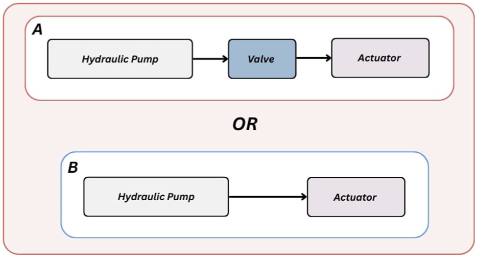
Architecture of decentralized hydraulic power units (EHAs), with A and B being the possible configurations. 104
Characteristics of EHAs.

FWR: force to weight ratio; PWR: power to weight ratio; PVR: power to volume ratio.
Taken from another article. **Estimated.
High force/torque output
The force/torque is the output given by the tip end of an actuator. Legged robots require exertion of significant force and torque to perform various tasks. For example, humanoids need high torque to support their weights, or in the case of the hand, a high grasping force for heavy tasks. 119 EHAs should be able to deliver the required levels of force and torque to enable the desired movements and interactions. The most recent EHA (Servo Electro-Hydraulic Actuator, SEHA), developed based on a patent of Samer Alfayad’s team 120 achieved the highest output force of 14.45 kN. 108 In comparison, Habibi and Goldenberg, 105 who developed the first EHA, reached a maximum output of 10.5 kN. Other notable contributions include Lee et al., 115 Kawasaki, 116 and Zhao et al., 107 with output forces of 7.68, 6, and 9.4 kN, respectively. However, achieving a high output force alone does not make an EHA suitable for legged robots, as it may come at the cost of other performance factors.
Lightweight and compactness
This requirement deals with having a small size and very reduced weight. Legged robots often have weight and size constraints which require pursuing size and weight reduction in every part. The reduction of occupied volume also makes the EHA highly integrable. 22 In this study, Ko et al. 114 has the most reduced weight of 1.2 kg while Kawasaki’s EHA 116 is the most compact with 910 cm3. However, the double standard approach shows that HAS possesses both reduced weight and volume in 2.5 kg and 662.48 cm3. It is further important to note that EHAs are meant to be compact and lightweight while still providing the necessary power and performance.
Force to weight ratio
This property which shows the relationship between the output force and weight of the EHA really evaluates the design of the EHA as there is an intuitively direct proportion between the output force of an EHA and its weight. A high force to weight indicates an EHA that alters the direct proportion between force and weight, hence satisfying double standards. Zhao et al. 107 achieved the highest force-to-weight ratio of 2.55 kW/kg, primarily enabled by their system’s design, which operates at a maximum pressure of 300 bars. In comparison, the SEHA 108 system attained an impressive force-to-weight ratio of 2.01 kW/kg with a maximum pressure of 210 bars.
High power output
The power output of EHAs shows the output force in conjunction with the speed of delivering it to the load. A high power output is indeed essential to make legged robots perform dynamic motion when carrying out different tasks. Many of the EHAs demonstrated power outputs around 1 kW. However, SEHA 108 achieved a remarkable output power of 15.17 kW, attributed to its high-speed capability of 1050 mm/s.
High power to volume/weight ratio
This property is concerned with the proportion of the power produced by the actuation system to its volume and weight. This property ensures an inverse relationship is established between the power generated by the actuator system and its corresponding size and weight. This ensures that measures taken to reduce the size and weight of the actuator don’t reduce its power output and vice versa, hence a high power-to-size/weight ratio. 22 Kawasaki’s design 116 stands out for its impressive compactness, demonstrating the highest power-to-volume ratio of 0.0024 kW/cm3. In contrast, SEHA 108 demonstrated an exceptionally high power-to-weight ratio of 2.107 kN/kg, significantly surpassing other units, all of which exhibited values below 0.5 kN/kg.
Low power consumption
The EHA unit usually contains an electric motor that generates rotary motion that drives the pump. The power consumption of this entity of the EHA unit needs to ensure low power consumption. This, in turn, characterizes the actuator system as a low-power consumption unit that grants the robot flexibility, adequate mobility, and high autonomous tendency.
The graph in Figure 16 shows the overall comparison of these EHAs. The main property that determines the operative effectiveness of an EHA in a decentralized architecture robot is the relationship between its mechanical output (force and power) and its dimension properties (size and weight).

Characteristics comparison of the EHAs—created from database.
Discussion
Leveling the ground for comparing both architectures
The hydraulic systems in centralized and decentralized architecture robots have both been implemented with close similarity to the general architecture. However, comparing them is challenging because of the uneven terrain for comparison. The following efforts were thus made to establish a level ground for comparing both architectures. Hence, centralized HPUs became leveled centralized HPUs.
As EHAs are self-contained structures, the hydraulic power unit of centralized architecture robots was adjusted to include the weight and leakage of the components (proportional valve, servo-valve, electric motor) that control the flow to the actuator.
The weight and pressure drop across the hoses used to connect the Hydraulic Power Unit (HPU) to the Hydraulic Drive Unit (HDU) of centralized architectures are taken into account to align with EHAs that have a reduced amount of hoses or none between their HPUs and HDUs.
Based on Table 7, which lists the cHPU parameters for centralized robots, only the following robots had the necessary parameters for comparison: Krupp’s Monopod, HyQ, MiniHyQ, MHT, and the unmounted cHPU of Ouyang. Similarly, from Table 10, the robots with the needed parameters were Said Habibi, Tianyi Ko, Maowen Sun (HAS), and Huipeng Zhao. Table 11 presents the updated data after applying the two specified conditions to the centralized robots. The initial values represent the parameters before the conditions were applied, while the final values show the results after applying the conditions using the outlined approach.
Leakage values and weights were obtained from the datasheets of the specific servo and proportional valves used in the robots.
Hose lengths were estimated based on the robot’s dimensions, and their total weight was calculated using the per-meter weight of the corresponding hose types.
Pressure drops across the hoses were determined using hose parameters and the length between the HPU and the farthest HDU.
The weight of the manifolds was estimated based on their dimensions and the material density.
Parameters of cHPUs after including the effect of leakage and pressure loss.

R in P: reduction in power; I in W: increase in weight; PWR: power to weight ratio in (kW/kg).
It can be observed from Table 11 that the power lost due to valve leakage and pressure loss can’t be ignored, as is the added weight due to valves, manifolds, and hoses. This led to a substantial reduction in the power-to-weight ratio.
It is important to note, however, that this “leveling” process was not perfectly balanced due to the inherent design differences between architectures. For EHAs, which are designed as self-contained units, the weight of the actuating cylinder is intrinsically included in the component’s total mass. In contrast, for cHPUs, our analysis focused on the power unit and its distribution network (valves, manifolds, hoses), excluding the weight of the final actuating cylinders, which are separate components. This methodological limitation, necessitated by the available data, means the comparison slightly favors cHPUs in the weight metric. While these considerations do not undermine the validity of our results, particularly the trends observed in power density, they do suggest that the true performance gap favoring EHAs is likely even greater than this study reports.
Architecture based comparison
After leveling the terrain of comparison between these two architectures, three key performance metrics (overall weight, power-to-weightratio, and individual joint power) were used for the comparison.
Power to weight ratio
The power-to-weight ratio is a crucial metric that evaluates whether the power output of an HPU justifies its weight. In Sun et al., 117 a comparative study was conducted between Ouyang’s cHPU 106 and the EHA called HAS 117 developed in their laboratory. To ensure a fair comparison, they matched the power density of four HAS units against the cHPU specifically designed to power four joints. Their results, summarized in Table 12, showed that HASs still retained a higher power density compared to the centralized hydraulic power unit, even though HASs can be dimensioned to meet the specific power demands of each joint thus saving weight, and minimizing cost.
HAS and Ouyang’s cHPU comparison.

Beyond comparing individual components, we extended our analysis to multiple cHPUs and EHAs, as illustrated in Figure 17. The purpose of this figure is to evaluate whether the common design logic of increasing component capacity in HPUs to obtain higher power output remains justified when considering the additional weight such increases typically entail. In other words, the figure examines how scaling up component size and weight affects the inherent high power density of hydraulic systems. This figure reveals a dynamic relationship between power-to-weight ratio and unit weight, showing that the inherent advantage of hydraulics in high power density can diminish as systems scale up.

Comparative plot of the power-to-weight ratio versus weight of electro-hydraulic actuators (EHAs) and centralized hydraulic power units (cHPUs)—created from database.
In Region A, the trend indicates that as weight increases, the resulting power output rises sufficiently to enhance overall power density. This direct relationship continues until a turning point, after which the trend shifts into Region B. In Region B, although power output still increases with added weight, the rate of increase is insufficient to offset the added mass, resulting in a decline in power density. Accordingly, Region A is defined exclusively by EHAs (Tianyi Ko, Maowen Sun, Huipeng Zhao, and SEHA), which achieve high power density at relatively low weights. By contrast, all cHPUs fall into Region B. Notably, even Krupp’s Monopod, which avoided long hoses by powering two joints located close to the pump, was grouped in Region B, since its performance matched Huipeng Zhao’s EHA at nearly four times the weight. This comparison underscores that the high power-to-weight ratio of hydraulics is best realized with lighter electro-hydrostatic architectures. Larger centralized HPUs, such as MiniHyQ, HyQ, and MHT, further exemplify this trend, confirming that scaling up centralized HPUs with heavier components undermines the defining quality of hydraulic actuation: its high power density.
Power per joint
The power per joint criterion examined the performance of leveled cHPUs by dividing their total output power by the number of joints powered, allowing a fair comparison with EHAs (with total output power in Table 10) which typically powered only a single joint. As shown in Figure 18, most cHPUs were positioned on the left side of the chart, reflecting lower power per joint values. An exception is Krupp’s monopod, which appeared among the EHAs on the right side, where higher power per joint values were observed. This deviation is attributed to the Krupp cHPU that powered only two closely positioned joints, reducing the losses caused by valve leakage and hose pressure drops, which resulted in a higher output of power per joint. The findings suggested that HPUs designed to power fewer joints, such as EHA and Krupp monopods, achieve superior power per joint performance.

Power per joint comparison of cHPUs and EHAs which showed HPUs powering fewer joints to have superior power per joint performance—created from database.
Summary of key findings from the review
This research targeted to elucidate the importance of making informed design decisions for HPU in legged robots, given their integral role in allowing robots to perform their intended functions. This was achieved by addressing the criteria for evaluating HPUs, examining how different HPU architectures affected key performance metrics, and identifying the scenarios best suited for each type of architecture. A state-of-the-art analysis of existing hydraulic-legged robots was conducted, followed by an architecture-based approach to highlight relevant performance metrics. Intra and intercomparisons were then made between EHAs and leveled cHPUs.
Comparison of the power-to-weight ratio between the two architectures revealed that EHAs exhibited a superior power-to-weight ratio compared to leveled cHPUs. Although cHPUs provided greater overall power output than EHAs, they lost efficiency in terms of power-to-weight ratio due to the added weight of valves and hoses, which also introduced power losses through leakage. The analysis further indicated that larger, more powerful components in cHPUs did not generate enough additional power to justify their increased weight, leading to a diminished power-to-weight ratio as weight increased. Furthermore, a comparison of power per joint revealed that EHAs delivered more power per joint than most cHPUs, with the exception of the Krupp’s monopod, which only powered two closely positioned joints. These findings suggested that the inherent advantage of the high power-to-weight ratio of hydraulic actuation diminished when the HPU was designed to power multiple joints, as seen in cHPUs. Consequently, the optimal design for HPUs should limit the number of joints to one (as in EHAs) or a few, ensuring that both output power and the overall weight contribution of the HPU to the robot remain optimal. In general, cHPUs are most effective when powering a small number of closely positioned joints, while EHAs, which may be underutilized in such scenarios, are better suited for powering multiple joints spread across greater distances.
Beyond architectural considerations, EHAs offer distinct control advantages over cHPUs owing to their decentralized, self-contained design and direct integration with control electronics. By eliminating long hydraulic lines and valve throttling, their compact, hoseless configuration reduces fluid delays and suppresses cross-coupling between joints, enabling faster dynamic response and more stable closed-loop control. 107 Unlike centralized systems, whose complexity and pressure losses degrade fidelity, EHAs provide a more direct drive behavior with lower latency, giving them an advantage in digital actuation and responsive control loops. Recent studies further demonstrate that EHAs support high-bandwidth force control, improved backdrivability, and active stiffness adjustment capabilities that are particularly beneficial for advanced strategies such as force, position, and impedance control. For example, compact linear EHA modules have been shown to exhibit favorable backdrivability and efficient power transmission, 121 while active load-sensitive EHA architectures allow adaptive pump displacement to modulate stiffness under varying loads. 122 Taken together, these properties enable EHAs to deliver superior control fidelity, real-time adaptability, and responsiveness compared to centralized HPUs, aligning them closely with the demands of modern legged robot control.
These findings suggest that EHAs provide a clear architectural advantage over cHPUs. Motivated by this observation, we examined how these advantages are being translated into ongoing innovation. In particular, we reviewed recent patents (2023–2025) in electro-hydraulic actuation, since patent activity often anticipates future industrial implementations. In this period, a notable concentration of electro-hydraulic and electro-hydrostatic actuator (EHA/EHSA) patents has been filed in China, reflecting a strong industrial interest in advancing this technology. These inventions cover a wide range of innovations, from integration and miniaturization to control flexibility and application to robotic joints and exoskeletons.
Several patents emphasize integration and structural refinement. For instance, Yuan et al. 123 proposed an integrated EHA based on magnetic modulation with a dedicated control method, while Li et al. 124 designed an actuator with an oil-filling and exhaust structure to improve reliability. More recently, patents have targeted miniaturization and sensing integration, such as the small-sized EHSA of Dong et al. 125 and the sensor-embedded design of Xiao et al. 126 Together, these designs suggest a clear industrial push toward compact, lightweight, and self-sufficient actuator modules suitable for distributed robotic architectures.
Other patents highlight performance enhancement and robotics applications. Zhou et al.127,128 described a self-driven dual-variable EHSA and a high-burst EHA for improved energy efficiency and dynamic output. Li et al. 129 filed an EHSA specifically designed for robotic joints, while Wang et al. 130 focused on exoskeleton robots with an electro-hydraulic servo actuator. Additional innovations include a rotary EHA with an outer rotor configuration 131 and a generic EHSA design by Huang et al. 132 These developments illustrate that patents are targeting both higher output capabilities and broader application domains.
In summary, patent activity from 2023 to 2025 indicates that the future of electro-hydraulic actuation will be characterized by compact integration, enhanced control, and application-specific customization, aligning closely with the advantages of EHAs over cHPUs identified in this review.
Conclusion
This comprehensive review of manufactured legged robots moves beyond a simple inventory of HPU architectures to provide a critical, data-driven synthesis of their real-world performance trade-offs. Our analysis revealed a fundamental divergence in power density and scalability between the two primary architectures. We found the differences to be:
Centralized HPUs (cHPUs): While capable of high total power output, they suffer from diminishing returns. Our findings show that as cHPUs scale up to power multiple joints, their power-to-weight ratio progressively degrades. This is due to the cumulative mass of valves, manifolds, and hydraulic lines, as well as inherent inefficiencies from leakage and pressure loss.
Electro-Hydraulic Actuators (EHAs): Conversely, EHAs demonstrate a consistently superior power-to-weight ratio. Their self-contained, hoseless design eliminates the parasitic mass and inefficiencies that plague large cHPUs.
The novel insight from this synthesis is not simply that EHAs are lighter, but that cHPUs possess a clear scalability limit that makes them fundamentally ill-suited for complex, multi-jointed limbs. This finding leads to a direct and actionable practical implication for designers: cHPUs are only efficient when powering a small number of co-located joints. For all other applications, particularly agile robots with multiple, distributed joints, EHAs represent the superior architectural choice.
This review argues that the potential of EHAs in legged robotics is significantly underexploited. The practical implications extend beyond power density; the inherent properties of EHAs, such as faster dynamics, reduced latency, high bandwidth, and improved backdrivability, make them intrinsically compatible with advanced force and impedance control strategies. While our study was not a review of control, our architectural findings strongly suggest that the widespread adoption of EHAs could unlock new levels of dynamic performance currently inaccessible to cHPUs.
Future research should therefore focus on the integration challenges of multi-EHA systems. Furthermore, investigations into hybrid electro-hydraulic schemes and the inclusion of other key metrics, such as power-to-volume ratios and cost-effectiveness, will be crucial in developing a truly holistic design framework for the next generation of high-performance legged robots.
Footnotes
Handling Editor: Lianjun Wu
Funding
The authors disclosed receipt of the following financial support for the research, authorship, and/or publication of this article: This work was supported by Kalysta Actuation.
Declaration of conflicting interests
The authors declared no potential conflicts of interest with respect to the research, authorship, and/or publication of this article.