
Abstract
Humanitarian demining is a calamity of war affecting many third world countries. Mines are cheap weapons, built to sustain horrible injuries that target active people with a knock-on effect upon economic growth. The clearing is time consuming and expensive. Clearing is an engineering duty and the humanitarian goal is a technical challenge. Advanced robotics fulfils this task cleanly and reliably on the condition that upgrades and cost are met, meaning that they lose third-world appropriateness. The challenge is to turn local machines and awareness into effective robotic aids, willingly used by the local people, and to enhance the on-going outcomes.
The solution to the demining problem shall be a low cost robotic outfit with resort to nearby available resources and competences (e.g., drawn from the local agricultural machinery and know-how). This paper discusses an ongoing project that aims to develop a low-cost robot with intelligent remote-command abilities, as a cheap productivity upgrading, assembled from standard farming devices, through the shared know-how and commitment of locally involved operators. During the study, the authors have developed a low-cost robot capable of removing mines. The robot consists of modified agricultural components including its mobile carrier and the mine effector.
1. Introduction
Landmines affect development of an area as they are a great barrier to human activities. This is particularly acute in agricultural areas where the landmine problem obstructs the lifestyles of people. Landmines are also a key factor in retarding the resettlement process. Affected countries like Sri Lanka lack funds to solve this problem within the required time and with the required efficiency. All the affected countries are developing countries and therefore there are key factors which should be considered by the researchers while they are developing technologies for demining. Cost, complexity, training, maintainability are the most important factors among them.
Demining consists of two main activities: detection and removing. Within the scenario of demining, a significant problem is detection of landmines [1]. For the detection process several sensors and robots have been implemented, but no single robot can guarantee 100% clearance [2, 3]. Once the mines are detected, the deminer would go to the site and remove the mines manually using the correct tools and methods. The removing process is also a dangerous task. The reliability of detecting landmines is low as non-metal landmines cannot be detected by metal detectors [4]. The next important fact is that the available demining machines are extremely expensive [5]. The cheapest machine which can be used for demining processes costs at least US$ 450,000. Also, manual removing of landmines with human involvement is not efficient, time effective and is also a hazardous process [6, 7]. Few autonomous robots have been suggested and implemented by researchers, but most of them are not used in practice as the demining process is not a clean and easy process [8, 9, 10]. Therefore, low-cost, reliable and user safe machinery is required for landmine removing.
The objective of this project is to address these requirements at a satisfactory level. In this project a landmine removal robot is developed. The robot can be used to remove landmines which are buried in pre-defined patterns called “mine- belts” and also for random buried landmines [11, 12]. The robot is designed to bear an unexpected explosion while it is operating. The structure of the robot was designed considering the minimum effect to the tractor unit, as well as soil cutters and sifter, in the event of a sudden explosion.
The paper develops as follows. Section II explains the system design of the robotic outfit (remote-governed carrier and duty-driven end-effectors). Then the instrumental fitting and programming settings for remote command of the robot are discussed in Section III. Section IV presents the construction and testing details of the system and finally, the conclusions are given in section V.
2. System design
The overall architecture of the example robotic outfit is shown in Fig. 1. The core module of the system is the vehicle which consists of a tractor unit.
The robot is assembled from standard agricultural equipment after slight modification to assure the cheapest integration setting and friendliness of operation capabilities. The final equipment consists of:
the self-powered carrier, permitting the robot autonomic mobility;
the demining effectors, assuring the safe unmanned mine clearing;
the remote command setting, of the steering and overseeing tasks.

Robot-Aided Mine Sweeper (RAMS) design
The single-axel power-tiller is chosen as the basic carrier with slight modification. Pneumatic actuators are used for steering and it is stabilized by the front effectors' axle, Fig. 2.

Robot-Aided Mine Sweeper (RAMS) design
Two demining outfits are conceived:
ground stripe lifting and mines singling out by sieve descent of the shifted earth;
land clearing by front displaced striking flaps and flounders, causing mine explosion.
The first is inspired by the potato digger, which is used for gentle lifting of the tubers and soil separation over a vibrating sifter. The rig front is equipped with tilting prongs, to assure the smoothest ground penetration, up to the safe depth (150 mm). The drag pressure never exceeds the mine threshold and the pulling out is achieved without direct contact with the mine body, as with potatoes to not damage the tubers. The conceived effectors are modified, to present a broadened active front up to 1.5 m wide, allowing the direct processing of properly extended ground stripes.
The effectors' axle stabilizes the (single-axle) power-tiller, supplying the front support (in lieu of the operator, on the back). The assembled vehicle has a rear-powered axle, pushing the front (idle) axle, with the inherent instability of the pushing setting. The RAMS' equipment, with the modified potato digger effectors, is applied on recently worked pastures or soft sandy lands. RAMS' system design is basically divided into two major steps;
design and construction of soil digger and shifter;
design of a communication module which interconnects GUI and robot.
2.1. Implementation of the soil digger and the shifter
The modified potato digger is used as a soil digger tool for the gentle lifting of the tubers and soil separation over a vibrating sifter [14]. The rig front is equipped with tilting prongs, to assure the smoothest ground penetration up to the safe depth of 150 mm (normally landmines are buried at a depth of around 100 mm).
The soil digger tool was designed with Solid Works 2010 and stresses applied on each part were analysed using the same software. According to the results of the analysis, suitable materials were selected. For practical implementation due to limitation of funds, steel is used for manufacturing the tool. The angle and depth controlling actuators are also replaced by a screw mechanism because the existing hydraulic system was insufficient to drive two additional actuators.
The sifter (soil shaker) is used to collect the mines in the processed ground area. The mesh is used for extracting the mines from the processed soil by the soil digger. All the equipment which has to be attached to the tractor unit is not fixed permanently to facilitate their separation from the tractor. Whenever possible all the additional structures, RAMS assembly parts, can be easily removed from the tractor, Fig. 3.

RAMS assembly
2.2. Draft force calculation
Developing and constructing a tool for soil digging purposes is the key structure of the project. The calculation of the draft force is based on the earth moving equation [15] with necessary modifications as shown in the Fig. 4.

Force acting on a rod
For calculation of maximum force in the worst case, it was assumed the effective width of the cutting tool is equal to total width, not the summation of elements' width. For the calculation, the following properties of the soil [16] and the tool have been used, Table 1.
Properties of the soil and the tool
The calculated values for vertical component and horizontal force were Fx= 3494 N and Fy= 5600 N, and the total force acting in a single element of the tool was 550 N.
The values obtained theoretically were also verified through practical tests. The observed value during the trials was around 600 N. The practical value deviates from the calculated value due to the presence of stones and large particles in the soil. A special rig was used for measuring the draft forces for driving a metal rod into the ground, Fig. 5. The angle of the metal rod was driven towards the ground and its length varied in range, so it was easy to find the optimal values for constructing the main structure.

The assembly used to calculate forces practically
3. Instrumental fitting and programming settings for remote command
The choice of the instrumental fitting favours the resort to off-the-shelf devices and standard software aids. The choice faces two fundamental demands:
friendliness, to guarantee clear-cut operability for hastily trained operators and leanness in view of easy maintainability and rugged on-the-field equipment;
low-cost, to make profitable the direct resources assembly from on-the-market offers, and effortless integration of cheap and well-assessed technologies.
The remotely-governed robotic equipment avoids cables and umbilicals, and resorts to self-powered carriers and wireless communication between self-sufficient stands [17, 18]. The data-exchange channel is used for command and overseeing tasks.
Two video cameras allow monitoring of the on-board ground processing and at the effectors front-area, to recognize warning symptoms and adaptive cues. The control has two processors: an on-board unit and operator station. The on-board unit oversees the path and ground processing tool, and supports the wireless communication with the operator. The operator stand is endowed with a simple notebook, having wireless I/O and standard software installed on it, Fig. 6.

The control (on-board/remote stand) architecture
The twin processors' setting, on-site and at the operator stand, permits closing control loops, for autonomic operation, which only needs afterward acknowledgement of the standard on-duty - either the recovery/withdrawal manoeuvring. The man/machine interface, Fig. 7, is organized following the virtual instrumentation (VI) concept. The display shows the visual feedbacks, coming from the two cameras (one at the effectors' front, one showing the ground processing duty) and several keys for the operator control.

The man/machine interface: display
The graphical user interface (GUI) is used to send commands to the robot and to also display the sensor readings. It was initially implemented using the virtual instrument concept.
The main assisting features of the developed GUI are as follows:
to specify the running control mode;
to display the camera views (switching between front view and soil shaker view);
to select the macro command mode;
to operate through pace-wise commands;
to change the autonomic to pace-wise and vice versa;
to accomplish the alarm management;
to perform the database access;
to carry the on-the field mapping;
to assist the data-base management.
The graphical user interface code is used to display all the data collected from the sensors, making use of the virtual instrument routines. On the computer's screen (INDICATORS), the virtual instruments are directly addressed during the RAMS' implementation phase, for the different data manipulation duties, notably, for the programming of the «macros», where different elemental actions on the actuators are assembled to produce a synthetic command.
The autonomic and pace-wise modes are alternative ways to command the carrier and the effectors, Fig 8. When the operator pushes LEFT TURN, the macro button sends the signal to the on-board processor through the Wi-Fi.

Inter relationship of the command directives
Then, the procedure called LEFT TURN will run locally to operate the necessary actuators' sequence, accomplishing the pertinent tests. A switch is available to the operator to change the autonomic mode to pace-wise or vice-versa according to her/his requirements.
The VI option is also exploited in the RAMS' programming phase, to establish the diagnostic reference and the «alarm» set-up. The idea is to feed the operator with a «series of alarms», warning either emergency, depending on the detected anomaly. All the alarms are coded according to the received sensors' data, in terms of thresholds and trends, or depending on the confrontation between simultaneous or history information.
There is another option which is OPEN TO OPERATOR to see the map of the navigation path. The current position of RAMS is calculated and sent to the operator station via Wi-Fi, from the on-board processor using the distance sensors. This value is stored in an Excel sheet and when the operator asks the location, a Labview routine uses these data to map the current position of the robot, a special purpose «macro» built on the specific sensor's data.
The data recording organizes, distinguishing three levels, Fig. 9:
the path registration procedure, to document the work done, through detailed maps;
the mine-sweeping agendas, to show the tactical charts, chiefly, coded into «macros»;
the alarm-steered occurrences, to provide better diagnostics and mending instances.
The idea is to create (in the operator's notebook) a database of past/current conditions, to exploit the acknowledged outcomes memory, and boost the on-process decision-making. The issue is checked in the field, with the direct involvement of the demining personnel. The mapping part of the database is helpful to the operator, to know the cleared area of the mine field.

Link between database and the PC
All the coordinates are calculated by the on-board processor according to the beacon navigation method stored in the database vs. the path progression [19]. When a mine is found, the operator properly tags that place through the interface, as a newly found mine location. Then, the data is stored in the database, and when the operator asks to generate the map of the cleared area, the controller retrieves the data from the mapping database and draws the map with the mine locations.
The control part of the database keeps the mine-sweeping agendas, to show the tactical charts, chiefly, coded into high level macros. Apart from that, all the set limits of the sensors' outputs are, moreover, stored in the peripheral database. The operator can change the set values of any sensor, through the user interface. These set values are used by the peripheral controller, to generate the warning/emergency signals.
The alarm-steered occurrences are part of the on-board diagnostic, to be stored in the database. The on-board diagnostic stores all the details about the alarm, including time and location. The operator has the ability to add or delete any information, through the standard requests over the user interface (database management). The low level functions deferred to the on-board processor permit closing the front-end checks directly, out of any faulty data transmission occurrence. The choice is planned to enhance the RAMS' on-duty reliability. All the instrumental fittings and programming setting aids are readily available from the market.
4. Construction and testing
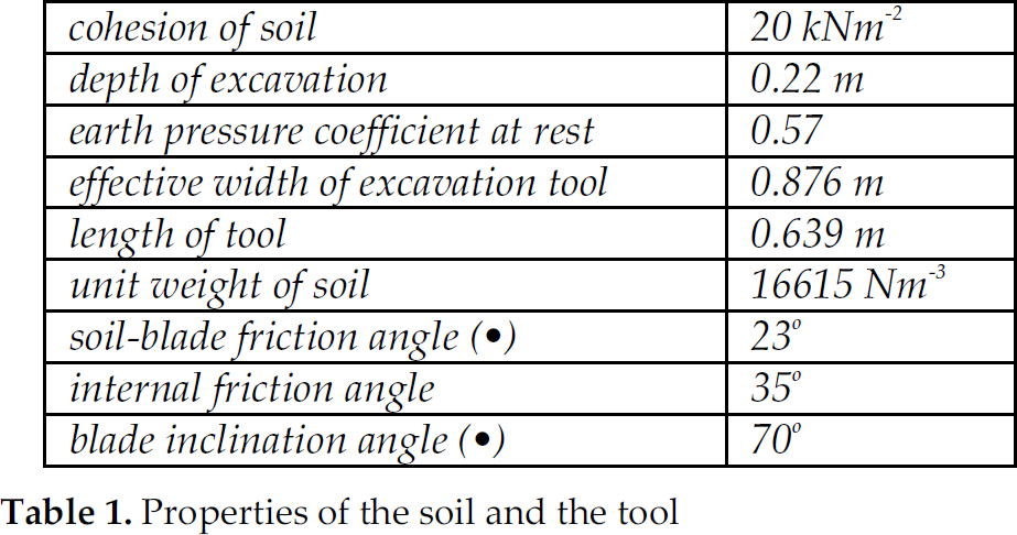
For the construction, a hydraulic system was used for controlling the actuators. The gear shifting method was also modified so that the tractor was capable of moving forward and backward with the use of a remote controller. Shifting in between faster gears is not considered when modifying the gear shifting mechanism as a high torque is required. The angle and depth of the soil digger tool can also be controlled. The tractor unit can be operated manually because normal controllers existing in the tractor unit are not removed in the remote controlling process. The constructed RAMS' tool is shown in Fig. 10.
Demining tool of RAMS
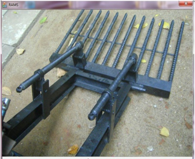
The machine faced difficulties in going forward during the testing once it hits any obstacles such as stones: this can be overcome easily by controlling the angle and the depth of the demining tool. The required force for the digging can be reduced further by vibrating the demining tool. This can be done by introducing a cam shaft mechanism as shown in Fig. 11.
Cam shaft mechanism
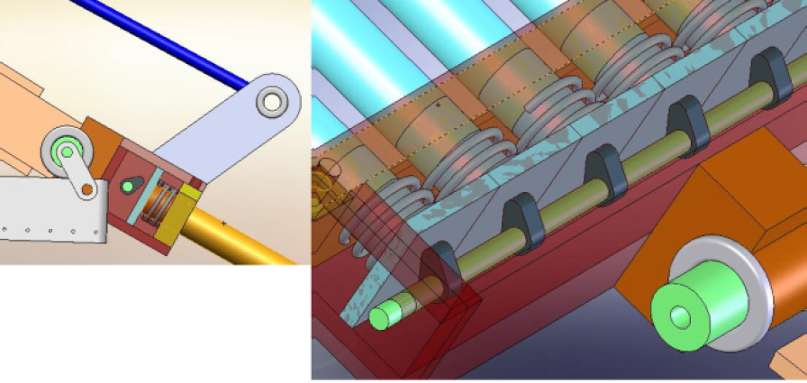
For safety purposes and to identify the position of some levers, limit switches and proximity switches are used, also for avoiding over stresses on the soil digging tools. If safety limits are exceeded, the micro controller identifies it as an emergency and automatically turns off the relevant mechanism. It required high power to control the steering system, gear shifting and clutch, which was achieved through a hydraulic system. The hydraulic pump was the power source which was used to control the actuators. The used hydraulic pump was driven by a three phase induction motor as shown in Fig. 12.

Hydraulic system components
The hydraulic pump was driven by connecting a sprocket wheel to the motor shaft which was connected to the driving pulley in the tractor by using a chain mechanism. There are three hydraulic actuators and three directional valves to control the clutch, gear and the steering mechanism. The robot vehicle was designed to get power from two serially connected 12V batteries. Batteries are charged by using the available induction generator. C-2C configuration was used to obtain a single phase AC output from the three phase induction generator [20]. The output voltage was stepped down, rectified and regulated to obtain a constant 28V DC supply which was required to charge the batteries.
It should be noted that this kind of mechanical removal of mines cannot guarantee 100% reliability and this process is strongly dependent on ground conditions. To improve the reliability, the angle of the tool should be changed according to the soil type while maintaining the correct depth. The correct angle should be set by the operator after field testing as it is difficult to model. Despite that the developed robotic system is an effective tool especially in all cases when positions of mines are not possible to predict, e.g. when the terrain is covered by thick vegetation. The efficiency of this system can be improved by cleaning the same area several times.
5. Conclusion
Landmines are one of hazard resulting from war and are a huge barrier to improving conditions for peoples in areas which were subjected to war. There are billions of landmines buried under soil all over the world and this problem has not yet been properly addressed. Landmine manual removing methods, such as mine detection with the use of metal detectors, are unable to guarantee 100% reliability due to plastic landmines and the process is too slow compared to demining machines. Some other manual demining methods are available, such as explosive detectors and use of animals, but the processes are very slow and not safe, therefore, the ultimate solution is a demining machine. The major problem of available demining machines is that they are too expensive, therefore, within this project the authors have implemented a low-cost, automated and safe demining machine.
When considering the challenges of demining in Sri Lanka, it is vital to understand the importance of developing new technologies or introducing existing current technology to improve the efficiency of the task, but only with proper training. The existing technologies have higher operating costs and higher capital costs. They also need well-trained personal to operate them. The available machines use various technologies for destroying mines rather than removing them. When doing so, there is high probability that unexploded mines remain in the ground. The solution to the demining problem shall be a low-cost robotic outfit with resort to nearby available resources and competences (e.g., drawn from the local agricultural machinery and know-how).
In this project, the first step was to design and develop a low-cost, suitable and reliable control system for demining. Furthermore, the secondary objective of the project was designing a low-cost demining tool, adopting cheap agricultural tools: the constructed tool is a model of the actual design.
The tested mine field was not flat and not cleared. Therefore, it was difficult to control the power-tiller in a straight path. The demining tool created large dust clouds and the high vegetation restricted the operator's view on the machine. Also, this machine is not intended to be used in areas where Anti Tank (AT) mines are present, but it is difficult to divide mine fields into those with and those without AT mines. Therefore it is useful to use some methods to avoid the blast sustained from an AT mine. In the near future, the intention is to solve on-duty programming problems in the field with the help of end users.