
Abstract
A novel mobile serial–parallel mechanism with legs for in-pipe use is proposed. The mobile robotic mechanism is composed of two identical three-universal joint–prismatic joint–universal joint parallel mechanisms connected in series and two gripping modules. The proposed parallel mechanism has two rotational freedoms and one translational freedom. In addition, the parallel mechanism can achieve continuous and equivalent rotation. The singularities of the parallel mechanism are analyzed. The overall serial–parallel mechanism has six degrees of freedom, and each gripping module has four degrees of freedom. Each parallel mechanism in the waist module is driven by three servo-electric cylinders and each leg mechanism in the gripping modules is controlled by a linear actuator. The robotic mechanism can perform peristaltic movement and turning in space. The robotic mechanism possesses a simple structure and high flexibility, along with the merits of serial–parallel mechanism. In this article, analytic models for the kinematics and dynamics of the robotic mechanism are derived. Additionally, numerical examples are given, and their solutions are validated based on results obtained by SimMechanics and Adams.
Introduction
A peristaltic robot is a bioinspired robotic mechanism that mimics the locomotion of an inchworm. Based on their principles of motion, peristaltic robots might be employed in pipes or other restricted areas. Wan and Yao 1 designed an in-pipe inchworm robot based on a three-revolute–prismatic–revolute parallel mechanism (PM). The robot is foldable and expandable and can perform large deformations. David and Moshe 2 presented a one degree of freedom (DOF) inchworm robot. Wael et al. 3 presented a miniature modular inchworm robot. Gao and Yan 4 designed an inchworm capsule robot for use in intestinal tracts. Yao et al. 5 produced an inchworm robot based on a serial mechanism (SM); however, the grippers in the robot have only one DOF, and thus, the robot lacks the ability to grip objects of different shapes. Xu et al. 6 presented a worm pipe robot based on the Stewart PM that can pass through pipes with complex structures, but has a poor ability to cross obstacles. Li et al. 7 proposed a hybrid 3-revolute-prismatic-revolute (RPR) mechanism with scalable platforms. Jeon et al. 8 developed a peristaltic mechanism with flexible links. The robot has a high flexibility; however, the flexible links installed in the robot limit its stiffness and traction ability. According to the literature, some conventional peristaltic robots exhibit poor traction ability or flexibility. The disadvantages of these robots limit their applications.
A serial–parallel mechanism (S–PM) comprises several PMs connected in series or a combination of SMs with PMs. 9 The S–PMs exhibit larger motion space compared with the SMs as well as higher rigidity, higher precision, and larger workload compared with the PMs. When a number of leg mechanisms (LMs) are mounted on the S–PM, its mobile ability and terrain adaptability can be greatly enhanced. Regarding S–PM robots, Peidro et al. 10 designed a truss-climbing robot with 10 DOFs based on an S–PM. Li and Yao 11 proposed a mobile S–PM that can pass through straight tubes. Wu and Du 12 designed an S–PM platform for legged-robot stability training. Tian et al. 13 designed a quadruped robot with S–PM legs, and Zheng et al. 14 presented an S–PM based on two types of PMs.
PMs with three active limbs are limited DOF PMs and exhibit a simple structure, easy control, and low costs. Unfortunately, some conventional PMs with two rotational and translational DOFs (2R1T PMs) lack rotational centers or axes, and thus platforms in the PMs can generate unexpected motion in the constrained DOF. The unexpected motion can also be called “parasitic motion” 15 and may complicate kinematic modeling and motion control. Research studies have been conducted to design PMs that realize continuous motion and eliminate parasitic motion. Chen et al. 16,17 presented a 3-DOF PM without parasitic motion. Xu et al. 18 investigated 2R1T PM types with two continuous rotational axes. This article presents a novel 3-UPU PM with 2R1T DOFs for construction of the robotic mechanism. This PM exhibits better motion properties than the PM designed in the study by Chen et al. 16,17 Furthermore, it can realize continuous motion and equivalent rotation. These properties are convenient for kinematic control.
The kinematics and dynamics of an S–PM with legs are studied here. The primary objectives of the kinematic study are to conduct displacement, velocity, and acceleration analyses. The establishment and solution of the kinematic model are necessary to compute the mechanism errors, workspace, singularities, and dynamics of the system. 19,20 Dynamic analysis is the foundation of the system motion control and contributes to the investigation of dynamic characteristics. The results can be applied to dynamic simulations and for optimization of the structure and controller design. 21,22
This article describes a proposed mobile S–PM with legs that includes a waist module and two gripping modules. The waist module is constructed with two 3-UPU PMs connected in series and has six DOFs. Each gripping module has four DOFs. The robotic mechanism can conduct peristaltic movement and turning in space, making it appropriate for application in pipes and other confined spaces. Compared with conventional peristaltic robots, the proposed robot exhibits a simple structure and high flexibility, as well as the merits of S–PM.
The subsequent sections are organized as follows. In the second section, the proposed robotic mechanism is described. In the third section, the DOF of the PM in the waist module is analyzed. In addition, its continuous and equivalent motion characteristics are investigated. In the fourth section, the singularities of the PM in the waist module are discussed. In the fifth section, the kinematics of the robotic mechanism are investigated, and the relevant analytic equations are derived. In the sixth section, the dynamic model of the robotic mechanism is established. In the seventh section, the mechanism model is created in SimMechanics [version R2014a] and Adams [version 2017] to verify the correctness of analytic solutions. In the eighth section, the conclusions are summarized.
Robotic mechanism design
The configuration of the robotic mechanism is designed on the basis of the body architecture of inchworms. The three-dimensional model of the proposed robotic mechanism is illustrated in Figure 1. The model mainly consists of a waist module and front and rear gripping modules. The two gripping modules are attached on opposite sides of the waist module, respectively. The designed robotic mechanism is expected to be able to move in pipes or confined spaces.

Three-dimensional model of the robotic mechanism.
The robot mimics the inchworm motion for moving in a pipe. When the robotic mechanism climbs in pipes or confined spaces, its rear gripping module expands and grips the inner walls and advances its front portion by extending its waist module; next, the robotic mechanism draws its rear portion forward by retracting the waist module while expanding the front gripping module. The peristaltic motion of the mechanism is realized by repeating the abovementioned described gait.
Structure of the mechanism
As shown in Figure 1, the waist module comprises front and rear PMs connected in series and has six DOFs. The front PM, which consists of two platforms and three identical limbs, has identical structure to the rear PM. Each limb connects two platforms via a universal joint, a prismatic joint and a universal joint in sequence. The prismatic joint is active, and the universal joint is passive. The universal joint is composed of two revolute joints, which can be referred to as the inner revolute joint and the outer revolute joint. As shown in Figure 2, the two axes of the outer revolute joints in each limb are angled relative to the platforms and are coplanar and intersect; moreover, the two axes of the inner revolute joints are parallel to each other and perpendicular to the prismatic joint.
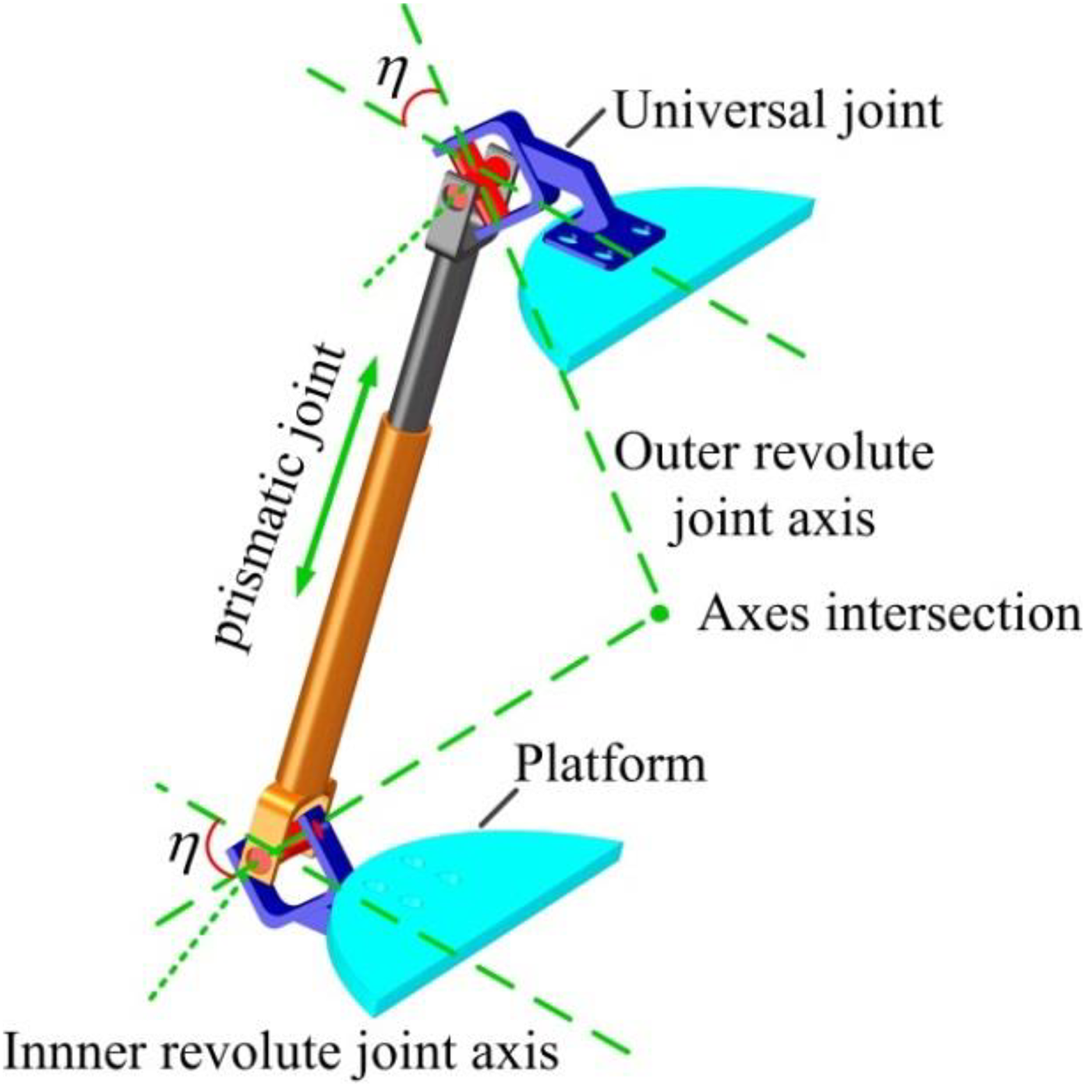
Description of one limb.
Each gripping module comprises four LMs. Each LM consists of a limb driven by a linear actuator, a leg and a frame. Each LM has one rotational DOF. Each of the gripping modules creates friction when in contact with the inner wall of a pipe, which enables the robot to hold its position inside pipes with different cross sections.
Design consideration
Material selection
During inchworm motion, the workload and most of the mechanism body are supported by one gripping module. Thus, the weight of the mechanism should be as light as possible, and the mechanism should have adequate strength to prevent overturning and resist structural deformation. All nonstandard components in the mechanism are manufactured using 7050-T7451 aluminum alloy. This type material has an ultimate tensile strength of 510 MPa, yield strength of 455 MPa, a low density, and a high strength to weight ratio.
Universal joint design
The rotational capacity of the universal joint affects the mobility of the PMs. The interference of the U-shaped frame is the main factor influencing on the motion workspace of the universal joint. To achieve large-scale rotation, the length of the revolute joint and the distance between the revolute shaft and the frame are increased simultaneously. The components that are consisted of universal joint are illustrated in Figure 3. The angular contact ball bearings are used to guarantee the rotational capability and positioning requirements of the two revolute shafts in each revolute joint. Additionally, a spline and pins are applied for axial fixation.
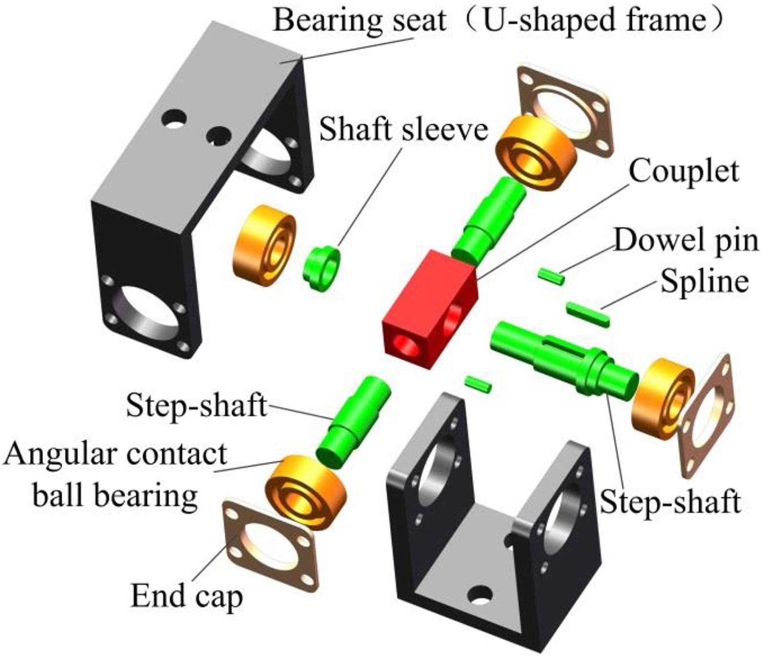
The three-dimensional model of components included in universal joint.
Actuator selection
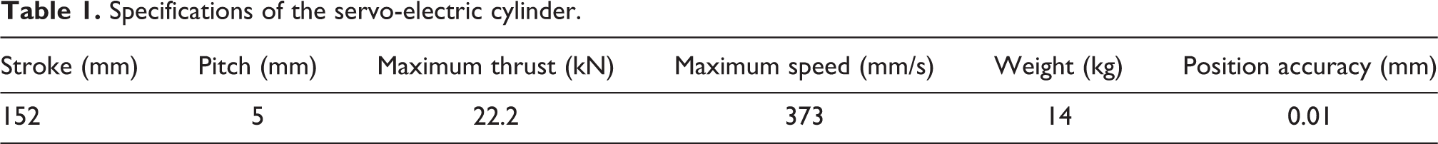
The robotic mechanism is used to allow the robot to climb in pipes or other confined spaces; thus, its structure should be compact and have a small volume and lightweight. In addition, the linear actuator used in the waist module should have reliable positional precision to provide the mechanism DOFs for positioning and orienting the robot in the motion space. Given these requirements, the servo-electric cylinders driven by servomotors are selected as actuators in the waist module. The servo-electric cylinder is mainly composed of servomotor and ball screw, which has 0.01-mm positioning accuracy. Its specifications are given in Table 1.
Specifications of the servo-electric cylinder.
Gripping module design
Each gripping module should be designed to bear the moment produced by the weight of the mechanism. Thus, as one of the gripping modules is held on the inner wall of a pipe, the other gripping module is able to freely detach from the inner wall. Each LM in the gripping module can operate over a certain range of pipe diameters and is not limited to a specific diameter. When the gripping module is in contact with the inner pipe wall, torque control is adopted in the linear actuators to control the gripping force. Furthermore, to increase friction with the inner pipe walls and ensure the safety of the mechanism, each leg should be attached with rubber. The specifications of the linear actuators used for driving legs in the gripping module are presented in Table 2.
Specifications of the linear actuator.

Model description
As shown in Figure 4, the rear PM in the waist module consists of an upper plate, bp 1, connected to a bottom plate, ap 1, by three identical UPU-type active limbs. The front PM includes an upper plate, bp 2, connected to a bottom plate, ap 2, by three identical UPU-type active limbs. In each PM, the three active limbs are evenly distributed around plates api and bpi (i = 1, 2). Each limb, Leij (i = 1, 2; j = 1, 2, 3), is composed of a piston, LEij , and a cylinder, LDij . The linear motion of LEij relative to LDij forms a prismatic joint, Pij . One end of the limb, Leij , is connected to front plate, bpi , by a universal joint, Uij 1. The other end is connected to the rear plate, api , by a universal joint, Uij 2. Each Uij 1 joint includes two revolute joints, Rij 1 and Rij 2, with mutual perpendicular axes, which intersect at point Bij . The outer revolute joint, Rij 1, is connected to the front plate, and the inner revolute joint, Rij 2, is connected to Leij . Accordingly, each Uij 2 joint comprises an inner revolute joint, Rij 3, and an outer revolute joint, Rij 4, the axes of which intersect at point Aij . The axes of two inner revolute joints are parallel to each other and perpendicular to the prismatic joint in Leij .
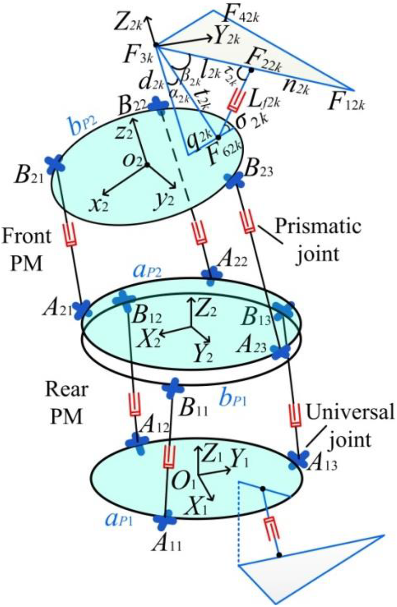
Coordinate systems of the robotic mechanism.
Let Li denote the ith gripping module from rear to front. L 1 and L 2 have identical structures and are fixed to plates ap 1 and bp 2, respectively. Li contains four identical LMs Li k (i = 1, 2; k = 1, 2, 3, 4) evenly distributed around ap 1 and bp 2. Each Li k with one rotational DOF is composed of an active limb, Lfik ; a frame, Mik ; and a triangular leg, Tik . Tik is hinged to frame Mik by a revolute joint at point F 3ik . Lfik consists of cylinder Lqik and piston Lpik . The bottom end of Lqik is hinged to the S–PM by a revolute joint at point F 6ik , and the upper end of Lpik is hinged to Tik by a revolute joint at point F 2ik .
Let {ai } denote the coordinate system Oi -XiYiZi located at center point Oi of plate api . The Xi -axis is parallel to line Ai 1 Ai 2, and the Zi -axis is normal to api . Let {bi } denote the coordinate system oi -xiyizi located at the center point oi of plate bpi . The zi -axis is normal to bpi , and the xi and yi axes are located on plate bpi . Let {gik } denote the coordinate system oik -xikyikzik located at point F 3ik in the kth LM of the ith gripping module. The global coordinate system of the robotic mechanism is {a 1}.
DOF and motion analyses of the ith PM
DOF analysis
In Figure 5, the axes of outer revolute joints Rij 1 and Rij 4 on each limb intersect at a point and the intersection points generated by the three limbs form a middle plane, mpi . Plate api and plate bpi are symmetric with respect to plane mpi . A local coordinate system, dij {O 2ij -X 2ij Y 2ij Z 2ij }, is defined for the jth limb. The coordinate origin, O 2ij , of each limb is situated at the intersection point. The X 2ij axis is parallel to the axes of Rij 2 or Rij 3. The Z 2ij axis is collinear with the axis of Rij 4.
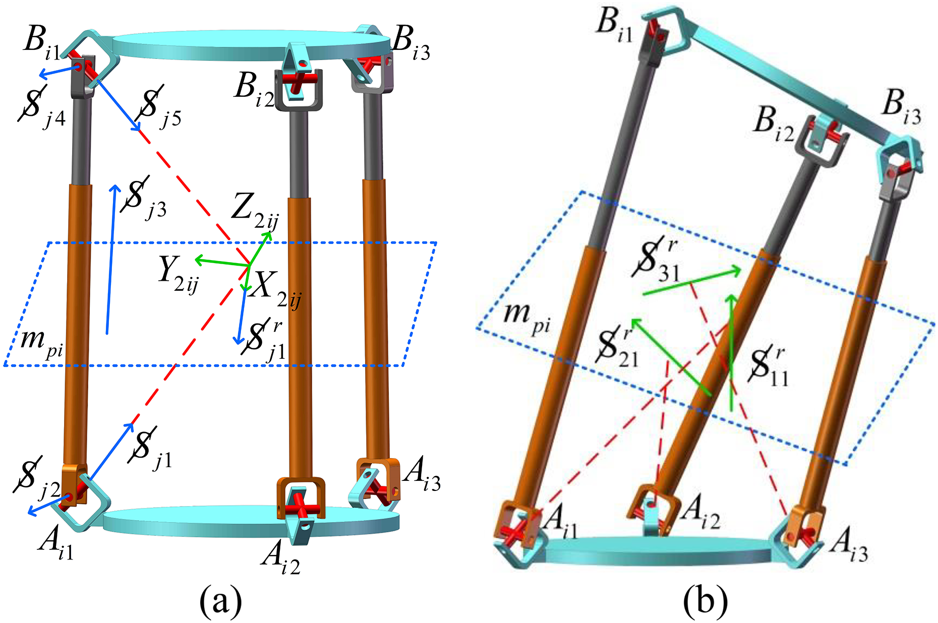
The ith PM in the initial assembly configuration (a) and in a general pose (b). PM: parallel mechanism.
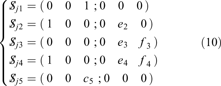
Let

where e 2, e 3, f 3, e 4, f 4, b 5, and c 5 are arbitrary variables.
Using the reciprocal product method, the reciprocal screw of the jth limb is derived as follows

where
The three limbs in the ith PM generate three constraint forces acting on bpi . Because the limbs are arranged symmetrically and plates bpi and api are symmetric with respect to mpi , the three constraint forces are clearly coplanar and intersect mutually at mpi . The condition of the three constraint forces is equivalent to two intercrossing forces and one couple perpendicular to mpi , as shown in Figure 6.

Constraint forces of the ith PM (a) and the equivalent model (b). PM: parallel mechanism.
Accordingly, two translational freedoms along the mpi and one rotational freedom along the normal direction of mpi are restricted. The remaining three freedoms of the ith PM contain one translational freedom along the normal direction of mpi and two rotational freedoms about mpi . Therefore, the PM has 2R1T DOFs.
Continuous and equivalent motion
Figure 7 shows a schematic representation of the ith PM conducting rotational motion. Two planes, B
i1
B
i2
B
i3 and A
i1
A
i2
A
i3, are symmetric with respect to plane mpi
. We choose a point F on bpi
and point H on api
as references points. The connection between points F and H is perpendicular to plane mpi
; therefore, the two points are symmetric with respect to mpi
. Plane Cp
passes through FH and is perpendicular to a line, L, on plane mpi
. Plane Cp
intersects line L at point R. FR is perpendicular to L. Point R can be considered to be the rotational center of plate bpi
, and line L is the instantaneous rotation axis of plate bpi
. Point F moves to F′ as bpi
revolves about point R by the angle η. After plane mpi
revolves about axis L by θ/2, mpi
moves to

Schematic representation of PM rotation and translation. PM: parallel mechanism.
As point F is symmetric to H with respect to plane mpi , we obtain

After bpi rotates about line L by η, the geometric relationship becomes
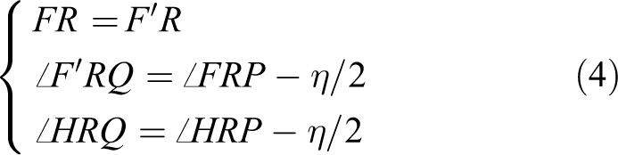
According to equations (3) and (4), we can obtain

Therefore, we obtain

According to equation (6), F′ is symmetric to H with respect to m′pi
. In the same manner, it can be inferred that plane
According to the DOF and motion analyses of the PM, the constraint forces are located on middle planes and any line lying on the middle plane can be treated as a rotational axis. When the PM rotates, the selected axis remains on the middle plane and can continue to be treated as rotational axis. Accordingly, the PM can perform continuous rotation with the selected axis. Furthermore, when the PM conducts translational motion, the two plates in the PM can be symmetric relative to the middle plane. In the process of translational motion, the new and previous middle planes are parallel to each other. Therefore, the PM can perform continuous translation in the normal direction of the middle planes. In addition, the PM lacks parasitic motion because of its continuous motion characteristics.
Based on the abovementioned description, the movement of F to F′ can be realized via rotation once around axis L. In the same manner, the movement of plane Bi
1
Bi
2 Bi
3 to
Singularity analysis of the ith PM
Kinematic singularity
Kinematic singularity is caused by the linear dependence of the joint screws in each limb and may decrease the DOF of the mechanism.
By referring to equation (1), the matrix composed of the Plücker coordinates of the joints in the jth limb can be written as follows
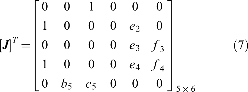
where all elements in the fourth column of the matrix [

If the matrix

From equation (9),
The reciprocal screw of equation (10) is represented as follows

Contrasting equation (11) with equation (2) reveals that a constraint couple is applied along the normal direction of the middle plane, leading to restriction of the rotational freedom relative to the Y-axis along the middle plane. Therefore, if the axes of outer revolute joints Rij 1 and Rij 4 are collinear and perpendicular to the plates in the PM, the kinematic singularity occurs in the ith PM of the waist module.
Constraint singularity
Constraint singularity occurs when all active joints in the PM are restrained. The constrained screws of the PM become linearly dependent, but the moving platform can still translate or rotate.
As illustrated in Figure 5, when the prismatic joints are restrained, the kinematic screw system of the jth limb in the local coordinate system {dij } is expressed as follows

where H denotes the distance from Aij to the plane mpi (i = 1, 2; j = 1, 2, 3), and φ denotes the angle between the axis of Rij 4 and plate api .
Based on equation (12), the reciprocal constraint screw yields the following

where
Kinematics of the robotic mechanism
Position of the S–PM
Let αi
, βi
, and λi
denote three Euler angles rotating around xi
, yi
, and zi
in coordinate {ai
} in order. As shown in Figure 8, the orientation of bPi
relative to aPi
is described by the rotational matrix

The coordinates of the ith PM. PM: parallel mechanism.
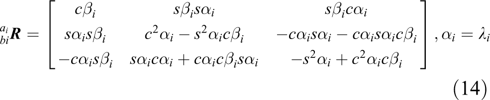
where cαi = cosαi , sαi = sinαi , cβi = cosβi , and sβi = sinβi .
For the
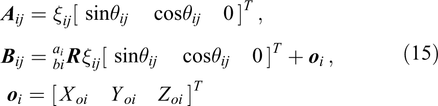
where ξij
denotes the distance from Oi
to Aij
; θij
denotes the angle between OiAij
and the Xi
-axis; and
As shown in Figure 8, the geometric vector equation for the jth limb in the ith PM is given by the following

where eij
is the length of the jth limb in the ith PM and
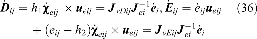
Let Dij
and Eij
denote the centroids of a cylinder rod and a piston rod in the jth limb, respectively. h
1 denotes the distance between Aij
and Dij
; h
2 denotes the distance between Bij
and Eij
;

As illustrated in Figure 4, the position vector of o 2 in {a 1} can be written as follows

Jacobian matrix of the ith PM
According to the analysis presented in the third section, the limbs in the ith PM generate three constraint forces and it has been proved that Rij
1 and Rij
4 intersect at point O
2ij
and that the constraint force,

where
By rearranging equation (19), we can obtain

where
The velocity of the prismatic joints in the ith PM can be expressed as follows

By combining equations (20) and (21), we obtain

where
Velocity and acceleration of the S–PM
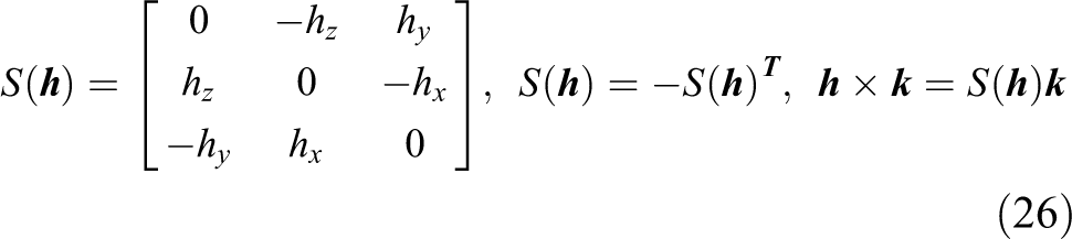
The linear velocity of oi and the angular velocity of plate bpi in {a i} can be expressed as follows

where

Based on equation (23), the general velocity of bpi in {ai } can be written as follows

where
If
By differentiating equation (18) with respect to time, the linear velocity of o 2 in {a 1} can be written as follows

The angular velocity of plate bp 2 in coordinate {a 1} is derived as

where
By combining equations (27) and (28), we obtain the general velocity of plate bp 2 in {a 1}

Using equations (20), (25), and (29), we obtain

By substituting equation (30) into equation (25), we can obtain

Based on equations (21) and (31),

Similarly,

where
The general acceleration of plate bp 2 in {a 1} can be written as follows

where
Let
where
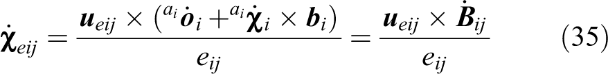
By differentiating equation (17) with respect to time, the linear velocities of cylinder and piston centroids Dij and Eij in the jth limb of the ith PM are as follows
The angular velocity of Dij and Eij is as follows

By combining equations (36) and (37), the generalized velocities of Dij and Eij are derived as follows

By differentiating equation (35) with respect to time, the angular acceleration of the jth limb in the ith PM is derived as follows
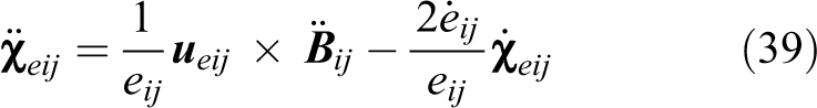
where
The linear accelerations of Dij and Eij are derived as follows

Velocity and acceleration of LM
As shown in Figure 4 let lik
(i = 1, 2; k = 1, 2, 3, 4) denote the length from F
2ik
to F
3ik
; fik
denote the length from F
2ik
to F
6ik
; and tik
denote the length from F
3ik
to F
6ik
. Let τik
denote the angle between lik
and fik
. Let

where
Based on equation (41), the velocity of point Tik
in the kth leg in {gik
} can be written as follows
where
By employing equations (41) and (42), the generalized velocity of Tik in {gik } can be written as follows

The position vector of point Tik on the kth leg in {a 1} is expressed as follows

where
By differentiating equation (44), the linear velocity of Tik in {a 1} becomes

The angular velocity of the kth leg in {a 1} is derived as follows

Using equations (45) and (46), the generalized velocity of the kth leg in {a 1} is derived as follows

The linear and angular accelerations of the kth leg in {a 1} are derived as follows

Dynamics of the robotic mechanism
Suppose
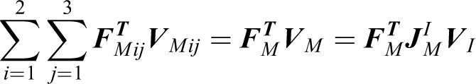
Based on equations (23), (28), (34), (35), (40), and (48), the component wrenches of the robotic mechanism are derived as follows

where
Considering the principle of virtual work, the power equation of the robotic mechanism is as follows

where
If we assume that

Based on equations (33) and (47), the power of linear actuators and legs in the gripping module can be written as

From equations (33) and (38), the power of linear actuators in the waist module can be written as follows

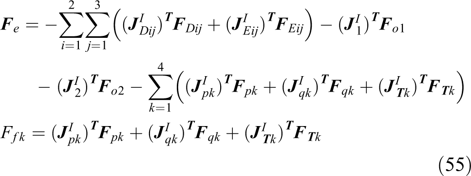
By substituting equations (51) to (53) into equation (50), we obtain

where
Thus, the actuation force applied to the prismatic joints of the robotic mechanism can be expressed as follows
Numerical examples
The kinematics and dynamics of the robotic mechanism are computed using the derived analytic models in the fifth and sixth sections. We assume that the rear gripping module grasps inner pipe wall, and its front part advances by extending the waist module. In the kinematics problem, the input velocities of actuators in waist module and front gripping module are given, and the task is to calculate the output velocities and accelerations of the center point in plate bp 2 and the velocities of legs in front gripping model. In the dynamics problem, the workload acting on plate bp 2 is given, and the task is to calculate the actuation forces of the waist module. To verify the correctness of the analytic results, the analytic results are compared with the solutions obtained by SimMechanics and Adams software.
The dimension, mass, and inertial torque of the mechanism are as follows: ξij
= 190 mm, LDij
= 300 mm, LEij
= 152 mm, m
i = 20.2 kg, mDij
= 15.6 kg, mEij
= 10.4 kg, mTik
= 30.3 kg, mpik
= 12.7 kg, mqik
= 10.5 kg, Ii
= diag[0.797, 0.4, 0.4] kg·m2, IDij
= diag[5.03, 5.05, 0.083] kg·m2, IEij
= diag[7.8, 7.8, 0.046] kg·m2, ITik
= diag[0.154, 0.149, 0.621] kg·m2, Ipik
= diag[0.86, 0.86, 0.13] kg·m2, and Iqik
= diag[0.54, 0.54, 0.523] kg·m2. The workload acting on plate bp
2 of the front PM are given as: F
1 = [0, 0, −1000]
T
N and T
1 = [−100, −150, −200]T N·m. The input velocities of actuators in the waist module are given as follows: ė
11 = 6t mm/s, ė
12 = 9t mm/s, ė
13 = 12t mm/s, ė
21 = 7t mm/s, ė
22 = 6t mm/s, and ė
23 = 5t mm/s. The input velocities of actuators in the gripping module are given as follows:
The virtual prototype of the robotic mechanism is established with Pro/E software [version 4.0], as shown in Figure 9. The model generated in Adams software is based on the virtual prototype. In the Adams environment, the architectural parameters, workloads, and initial input kinematics parameters are consistent with the analytic model. Each universal joint is substituted by two revolute pairs and there are 10 translational pairs and 36 revolute pairs in the Adams model. The solutions obtained by Adams are plotted in Figures 11(b), 12(b), 13(b), and 14(b). Figure 11(b) depicts the output velocities of the center point in plate bp 2, Figure 12(b) depicts the output accelerations of the center point in plate bp 2, Figure 13(b) depicts the output velocities of the legs in the gripping module, and Figure 14(b) depicts the actuation forces of the robotic mechanism.

The virtual prototype of the robotic mechanism.
As shown in Figure 10, the SimMechanics model of the mechanism is constructed according to the parameters used in the analytic model. In the SimMechanics environment, each prismatic joint is connected with a joint actuator. The joint actuator is used to specify the input kinematics parameters, which are the same as those of the analytic model. The results generated in SimMechanics are shown in Figure 11(a), 12(a), 13(a), and 14(a).

The mechanism model in SimMechanics.

Curves for the linear velocity of the center of plate bp 2: (a) analytic and SimMechanics results and (b) Adams results.

Curves for the linear acceleration of the center of plate bp 2: (a) analytic and SimMechanics results and (b) Adams results.
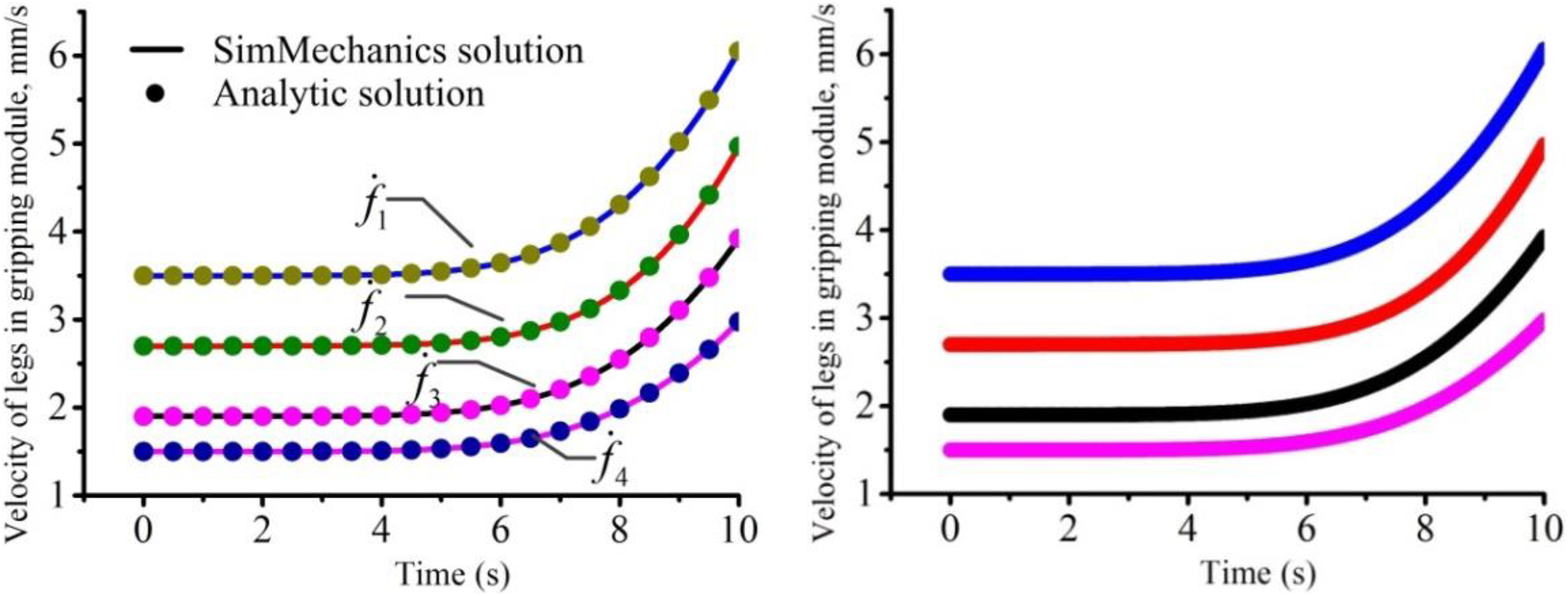
Curves for the velocity of the legs in gripping module: (a) analytic and SimMechanics results and (b) Adams results.

Curves for the actuation force of the waist module: (a) analytic and SimMechanics results and (b) Adams results.
Based on the results shown in Figures 11
to 14, the following conclusions can be drawn: As the input velocity of the mechanism changes over time, the output velocities and accelerations of the center point in plate bp
2 change smoothly. As the input velocity of the mechanism changes over time, the output velocities of the legs in the gripping module change smoothly. As the input velocity of the mechanism changes over time, the actuation forces of the robotic mechanism change smoothly.
Figure 7 shows that the actuation forces of the front PM are larger than those of the rear PM; thus, the rigidity of the front PM should be higher than that of rear PM.
By comparing the curves illustrated in Figures 11 to 14, it can be observed that the analytic solutions match well with the solutions obtained by SimMechanics and Adams software, confirming the reliability of the derived analytic models.
Conclusion
A novel S–PM with legs is presented herein, and its architectural features and advantages are described. The architectural design of the mechanism imitates the structure of a natural inchworm and comprises a waist module and two gripping modules. The waist module in the robotic mechanism has six DOFs and each gripping module has four DOFs.
The PMs in the waist module can perform continuous rotation about an axis on symmetric surface of two platforms and can exhibit continuous translation in the normal direction of symmetric surface. Any line lying on the symmetric surface can be treated as a rotational axis of the PM; thus, the PM lacks parasitic motion. As the PM can rotate from its previous position to a new position by rotation once about an axis, it can realize equivalent motion. According to an analysis of the singularities of the PM in the waist module are analyzed, if the two axes of outer revolute joints in each limb are collinear and perpendicular to platforms, kinematic singularity occurs. Because this configuration is not considered in the design, singularities cannot occur in the proposed PMs.
In the proposed approach, the relationships among the input and output displacements, velocity, and acceleration of the robotic mechanism are resolved by the derived kinematics models. Moreover, a dynamic model is established using the principle of virtual work. The analytic solutions are validated with the results obtained with SimMechanics and Adams. The theoretical approach can be used for other robots with similar architecture.
The proposed robot is mainly designed for climbing in pipes and other confined spaces; thus, it can be used for the detection of defects, rescue, and military tasks. However, as a result of the size limitation of standard linear actuators, the robotic mechanism can only climb in pipes with a certain range of diameters. In our future studies, we may develop nonstandard linear actuators and design a new mechanism structure that can climb all types of pipes.
Footnotes
Declaration of conflicting interests
The author(s) declared no potential conflicts of interest with respect to the research, authorship, and/or publication of this article.
Funding
The author(s) disclosed receipt of the following financial support for the research, authorship, and/or publication of this article: This work was supported by the National Natural Science Foundation of China (grant number 2016YFC0600900) and the Yue Qi Distinguished Scholar Project of China University of Mining & Technology(Beijing) (Grant number 800015Z1145).