
Abstract
This paper presents a novel mobile robot for urban search and rescue based on reconfiguration. The system consists of three identical modules; actually each module is an entire robotic system that can perform distributed activities. To achieve highly adaptive locomotion capabilities, the robot's serial and parallel mechanisms form an active joint, enabling it to change its shape in three dimensions. A docking mechanism enables adjacent modules to connect or disconnect flexibly and automatically. This mechanical structure and the control system are introduced in detail, followed by a description of the locomotion capabilities. In the end, the successful on-site tests confirm the principles described above and the robot's ability.
Introduction
The last few years have witnessed an increasing interest in reconfigurable mobile robotic technologies (Yim, M.; et al., 2000). The applications include the following areas: industrial inspection and conducting surveillance, urban search and rescue, military reconnaissance and civil exploration. Reconfigurable robots consist of several modules which are able to change the way they are connected. The modular approach enables mobile robots to reconfigure, which is essential for tasks that are difficult for a fixed-shape robot (Kamimura, A.; et al.; 2001). During movement the robot confronts an unstructured environment and handles the ensuing uncertainties by reconfiguring its structure (Castano, A.; et al., 2000). The basic requirement for this kind of robotic system moving on rough terrains is extraordinary motion capabilities.
In this paper the emphasis for discussion is on the field of urban search and rescue. It is a domain that involves a great amount of manpower; and dangerous and laborious work in a hostile environment. The development of mobile robots offers an intelligent alternative solution to the above-mentioned problems. The application of the right robotic system can relieve people of this challenging work and provide an opportunity for robots to play a pivotal support role, realize automatic manipulation in a complex environment and improve the level of civil and military technology.
In this paper, a novel modular reconfigurable mobile robot named JL-I is presented, which to date consists of three identical modules. After a short survey, the basic functions of a reconfigurable mobile robot are summarized systematically based on research into work targets. JL-I features active joints formed by serial and parallel mechanisms which endow the robot with the ability of changing shapes in three dimensions. With the docking mechanisms, the modules can connect or disconnect flexibly and automatically. Then the related kinematics analysis of the mechanical realization is discussed thoroughly as well. After that the discussion focuses on the various locomotion capabilities, such as crossing high vertical obstacles and getting self-recovery when the robot is upside-down. The results of a series of successful on-site tests are given to confirm the principles described above and the robot's ability.
Reconfigurable robots in literature
In recent years considerable progress has been made in the field of reconfigurable modular robotic systems, which usually comprise three or more rigid segments that are connected by special joints (Rus, D.; Vona, M.; 2000). The common kinematics modes include multiple legs, wheeled and chain-track vehicles. However, the robots with multiple-legs kinematics are too complex due to a structure with many degrees of freedom (Zhang, H.; et al., 2004). These robots do not meet the requirements of miniaturization, flexible and quick movement, so that multi-legs kinematics is rarely adapted.
Robots with a wheeled and chain-track vehicle are usually portable due to their high adaptability to unstructured environments. The first prototypical structure (Hirose, S.; et al., 1990) with powered wheels was designed by Hirose and Morishima in 1990 and consists of several vertical cylindrical segments. The robot looks like a train; however with a weight of over 300 kg it is too heavy. Klaassen developed a mobile robot with six active segments and a head for the inspection of sewage pipes (Klaassen, B.; et al., 1999). Twelve wheels on each module provide the driving force. Mark Yim (Yim, M.; et al., 2001) proposed another reconfigurable PolyBot which is able to optimize the way its parts connect to fit the specific task. It adopts its shape, becoming a rolling type to pass over flat ground, an earthworm type to move in narrow spaces and a spider type to stride over unknown hilly terrain.
The application of powered tracks to field robots enriches their configurations and improves the adaptability to the environment. A serpentine robot from Takayama and Hirose consists of three segments. Each segment is driven by a pair of tracks, but all tracks are powered simultaneously by a single motor located in the centre segment (Takayama, T.; et al., 2000). The special ability of adapting to irregular terrain is passive and provided by springs. The OmniTread serpentine robot (Granosik, G.; et al., 2005) was developed for industrial inspection and surveillance. Optimal active joints are actuated by pneumatic cylinders in order to compromise strength and compliance. Even if this prototype is quite adaptable, it is obstructed by a tube for pressurized air and cables for control signals connected to the supporting system on the ground.
However, the known robots usually can only assume few configurations due to relatively simple docking and pose-adjusting mechanisms. For example, the Millibot Train robot from Carnegie Mellon University consists of seven compact segments, which can connect by couplers with one DOF (Brown, H.B.; et al., 2002). A reconfigurable mobile robot designed by M. Park is not able to change its configuration actively (Park, M.; et al., 2004). Another recent module robot (Wang, T.M.; et al., 2005) has only one DOF in its pose-adjusting mechanism. The robot from Université Libre de Bruxelles (Sahin, E.; et al., 2004) has a one-DOF pose-adjusting mechanism and one coupler to change the configuration between the neighbouring modules as well.
Since 1999 our group has been focusing on the design and development of a reconfigurable mobile robot. A smart structure with two linked-track vehicles was proposed (Wang, W.; et al., 1999). The structure can be reconstructed so that the robot can move between surfaces standing at an angle of 0–90 degrees to each other. However, the construction stiffness is a little low so that there is a small distortion while moving. The project in this paper is intended to develop an automatic field robot for unstructured environments to meet the requirements of high flexibility, robustness and low cost.
System design and realization
Design considerations
Urban search and rescue is one important application for mobile robots in a complex environment. The basic functions of urban search and rescue robots include five aspects.
Locomotion capability
It is the lowest basic functionality of the robotic system, which includes the following details:
The robot works not only indoors but outdoors as well. It should have a flexible mobility in rugged terrain to get to every point in the work space. In order to finish a task in an unstructured environment, the ability to cross high obstacles and span large gaps is indispensable. Sometimes the working environment is very complicated, including not only high steps and deep ditches but also narrow fences and floors cluttered with debris. As a result, the robot should have the capability of adopting different configurations to match various tasks and suit complex environments.
Enough intelligence for the discrimination of a variety of obstacle situations
Multiple sensing and control systems are incorporated to handle the uncertainties in a complex environment. Software should be dexterous enough to identify the various geometries and intelligent enough to autonomously reconstruct the environment. Sensor fusion is an important capability since no single sensor can identify all aspects of the environment.
Working autonomously with the corresponding effective treatment
As a rescue robot, it should move as fast as possible in order to get real-time information. Once the global task commands are entered by the user, the robot should move while accomplishing the rescue task. Path planning and behaviour organization is built on global prior knowledge and local sensory information.
Few connections with the environment
In order to move freely, it is important for the mobile field robot not to be wired or otherwise connected to the environment. The robot should carry all it needs: onboard power, the controller, and wireless communication.
Cooperation ability
The rescue robot is designed to operate with humans. The level of interaction may vary significantly, depending on the robot's design and on the circumstances. The controlling and monitoring of the robot is achieved through a GUI to allow an effective and user-friendly operation.
Usually urban searching and rescuing is based on the cooperation in a team. The given targets will be assigned separately. Every robot should communicate with the others and perform distributed activities.
Prototype design
The proposed mobile system should have various moving modes. The JL-I system consists of three connected, identical modules for crossing grooves, steps, obstacles and travelling in complex environments. Design of the robot includes five parts:
Design of the independent mobile module which includes movement mechanisms and driving systems; Development of the docking system and the reconfigurable driving mechanisms; Development of the control system; Kinematics analysis; Experimental testing.
The mechanical structure of JL-I is flexible due to its identical modules and special connection joints (Fig. 1). Actually, each module is an entire robot system that can perform distributed activities (Fig. 2). Three DOF active spherical joints between two modules and the docking mechanism enable the adjacent modules to adopt optimized configurations to negotiate difficult terrain or to split into three small units to perform tasks simultaneously.
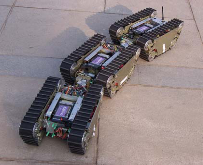
A photo of JL-I

Performing distributed activities
By combining such locomotion capabilities, JL-I will move in almost all kinds of rough environments. The principle of terrain adaptability is shown in Fig. 3. The robot can change its posture by pitching around the Y axis, yawing around the X axis and rotating around the Z axis. The yawing and pitching movements are achieved by the parallel mechanism. The third rotation DOF around the joint's Z axis is achieved by the serial mechanism.

Adapting to terrains
In contrast to the results of previous research, this robot includes the following innovative aspects:
It is known that a common mobile robot will lose its moving ability if it is not able to keep its balance. However, the JL-I with its many active spherical joints can smooth the undulating motion of the gravity centre of the whole system.
High adaptability
Identical modules in the JL-I robot have a large variety of configurations owing to the pose-adjusting joints and the docking mechanisms. Therefore, the robot can adopt many shapes which make the JL-I system able to carry out various different tasks and move in diverse environments.
Self recovering ability
Furthermore, JL-I has the ability to implement self-recovery. By disconnecting the malfunctioning module, the system can repair itself if one module does not work normally. In this way, working safety and efficiency are increased when the robot moves in a complex environment.
The module realization
The single module is about 35 centimetres long, 25 centimetres wide and 15 centimetres high. Fig. 4 shows the mechanical structure of the module which comprises two powered tracks, a serial mechanism, a parallel mechanism, and a docking mechanism.
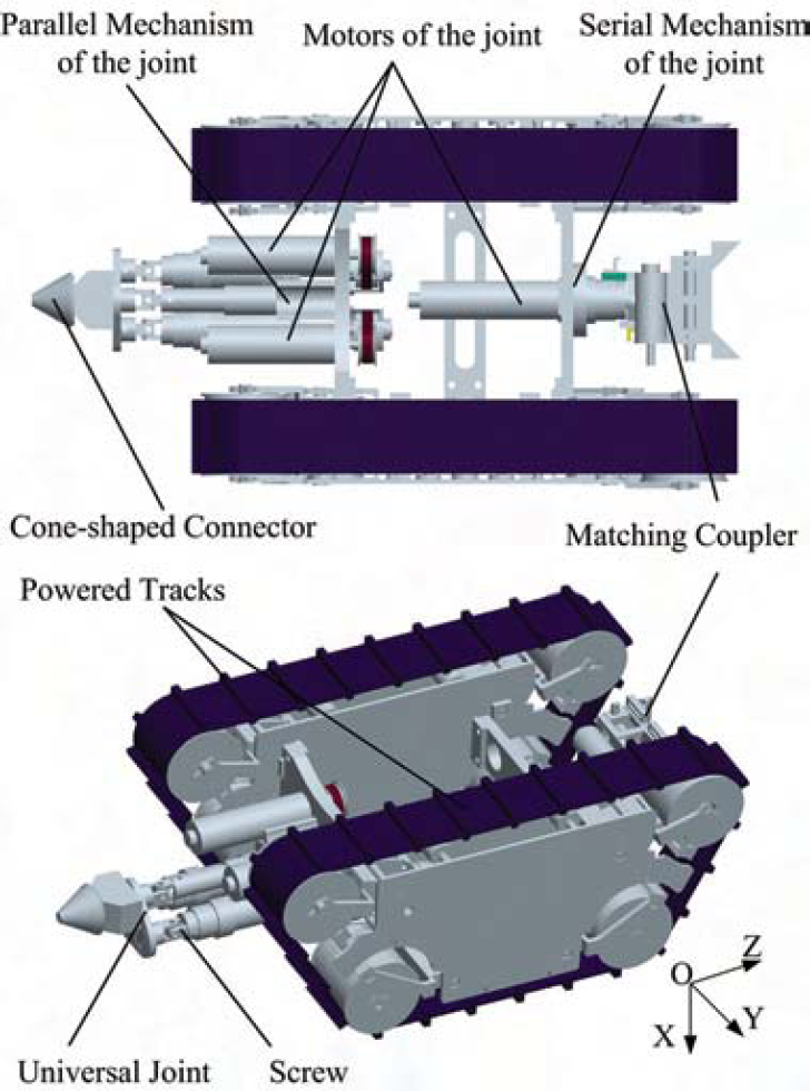
The mechanical structure of the module
Two DC motors drive the tracks providing skid-steering ability in order to realize flexible omnidirectional movement.
The docking mechanism consists of two parts: a cone-shaped connector at the front and a matching coupler at the back of the module, as shown in Fig. 5. The coupler is composed of two sliders propelled by a motor-driven screw. The sliders form a matching funnel which guides the connector to mate with the cavity and enables the modules to self-align with certain lateral offsets and directional offsets. After that, two mating planes between the sliders and the cone-shaped connector constrain the movement, thus locking the two modules. This mechanism enables any two adjacent modules to link, forming a train configuration. Therefore the independent module has to be rather long in order to realize all necessary docking functions. In designing this mechanism and its controls, an equilibrium between flexibility and size has to be reached.

The docking mechanism
The robot features the serial and parallel mechanisms which form a three-DOF active spherical joint, as shown in Fig. 6. There are two reasons for using serial and parallel mechanisms for our mobile robot. Firstly, the JL-I robot can be made lightweight and dexterous while allowing for a larger payload. Secondly, the advantages of the high rigidity of a parallel mechanism and the extended workspace of a serial mechanism can be combined, thus improving the flexibility of the system.

The serial and parallel mechanisms
The serial mechanism can rotate 360° around the Z axis. This joint is actuated by a geared minimotor which provides a continuous torque of 3.5 Nm at a speed of 30 rpm. The parallel mechanism can pitch around the Y axis and yaw according to the X axis. Each leg of this parallel joint consists of a driving platform, a universal joint, a screw, a synchronous belt system, a DC motor and a base platform. The universal joint connects the driving platform and the knighthead. The other end of the knighthead is fixed to the base platform. By revolving the screw, the driving platform can be manipulated relatively to the base platform. By controlling the active joints and the docking mechanisms, the robot can change its shape in three dimensions.
To ensure its ability of performing tasks individually, there is enough space in each module for sensors, the onboard controller, and batteries. Considerable stress is laid on weight reduction as well as on construction stiffness to achieve a dexterous movement mechanism. Most of the mechanical parts are designed specifically and mainly manufactured from aluminium. A module weighs approximately 7 kg including the batteries.
The control system of the robot based on an industrial PC (IPC) and a master-slave structure meets the requirements of functionality, extensibility, and easy handling (Fig. 7). Multiple processes programming capability is guaranteed by the principle of the control structure. The hardware consists of an SBC-X255, an independent image processing unit and a low-level driving unit (SBC 2).

Control system
The SBC-X255 is the core part of the control system. It is a standard PC/104+ compliant, single-board computer with an embedded low power Intel Xscale PXA255 (400 MHz). This board operates without a fan at temperatures from −40° C up to 85° C and typically consumes fewer than 4.5 Watts while supporting numerous peripherals. The Ethernet port is used as a communication interface between the IPC and the image processing unit which is in charge of searching and monitoring. The IPC is a higher-level controller and does not take part in joint motion control. Its responsibilities include receiving orders from the remote controller, planning operational processes, receiving feedback information.
The SBC 2 is in charge of driving five DC motors and receives and processes all related sensor signals. It can directly count the pulse signals from the encoder, deal with the signals from other magnetic sensors, and directly drive the DC motors forward and backward at different velocities. Meanwhile it sends all information to the IPC through another Ethernet port.
There are two kinds of external sensors on the robot: a CCD camera and touchable sensors, which are responsible for collecting information about the operational environment. The internal sensors such as a GPS, a digital compass, a gyro sensor are used to reflect the self-status of the robot. The gesture sensor will send the information on the inclination of the module to the controller. There are limit switches to give the controller the position of the joint. On the joint where the accurate position is needed, the optical encoder is used.
The DOF of the active joint
According to the mechanical principle, the DOF can be concluded first, which will lay the foundation for later discussions. As shown in Fig. 8, there are altogether 8 joints, described as g, out of which 3 joints are active and actuated by respective DC motors. There are three Hooker joints at points O, A, and B; two linear movement joints at links AC and BD; one rotating joint along the axis Z1Z2 and two spherical joints at C and D. According to equation (1), the DOF can be concluded.
Where m means the DOF; n means the movable links of the active joint. There are seven links totally. Where f
i
is the DOF of the relative joint. It is noted the DOF of a rotating joint and a linear movement joint is one; the DOF of the Hooker joint is two while the spherical joint has three DOF. All these results are inserted into (1) to get the DOF.


The kinematics mode of the active spherical joint
To demonstrate the reconfiguring possibility, the kinematics analysis of two connected modules should be studied as follows. Fig. 8 shows the kinematics model of the joint between two modules. Where OXYZ is the world coordinate fixed at the plane QEF which represents the front unmovable module during the reconfiguration. The origin is located at the universal joint O, the Z-axis coincides with the axis of the serial mechanism and the X-axis points to the middle point of line AB. Another reference coordinate O'X'Y'Z' is fixed at triangular prism OABPCD which represents the back moveable module. The O'X'Y'Z' is coincident with the OXYZ when the spherical joint is in its home state. Equations (2) and (3) are satisfied due to the mechanical constraints. QF is perpendicular and equal to QE.


The required orientation for the reference frame O'X'Y'Z' on the back module is achieved by a rotation of θz, a pitching angle θ
y
and a yawing angle θ
x
according to the relative axes. From the mechanical point of view, actually the pitching and yawing motions are realized by the outstretching and returning movement of the L1, L2 of the parallel mechanism, and the rotation of θz is actuated by the serial mechanism. The freedom of the reconfiguring movement is three and can be described with the generalized coordinate θ (4). The joint variants of the movement are named q, described as (5).


The purpose of the kinematics analysis is to deduce the relationship between q and θ. In Fig. 8, the points A, B, C, D are described as (6) in the OXYZ coordinate.
The homogeneous transformation matrix [T] from the world coordinate OXYZ to the coordinate O'X'Y'Z' is described as (7).

After the reconfiguring movement, A, B, C, and D are changed to new positions described as A1, B1, C1, and D1. The Cartesian coordinates of the new points can be expressed as (8) and (9).


The lengths of the link L1 and L2 are equal to the distance between C1A1 and D1B1 respectively. All these results are inserted into (8) and (9); resulting in equation (10), (11).


Named

Relevant successful on-site experiments with the mobile robot were carried out recently, confirming the principles described above and the robot's ability.
The docking process
Fig. 9 shows the docking process of the connection mechanism whose most distinctive features are its ability of self aligning and its great driving force. With the help of the powered tracks, the cone-shaped connector and the matching coupler can match well within ±30mm lateral offsets and ±45° directional offsets.

The docking process
Compared to many configurable mobile robots, the JL-I improves its flexibility and adaptability by using novel active spherical joints between modules. Fig. 10 shows the process of climbing stairs.

Climbing stairs
Fig. 11 shows the process of crossing a step which is almost twice as high as the robot.
The robot is in its home state, and the sensor is detecting the step in the movement direction. The first module is pitching up around the Y axis while the robot is moving forward. The approaching movement does not stop until the first module is touching the step. Then the first module is pitching down to attach to the top of the step. The robot is moving until the first two modules are attached to the step. The last module is pitching up around the Y axis while the robot is moving forward. The robot is now in its home state again, and the process of crossing the step is over.

The sequence of crossing a step
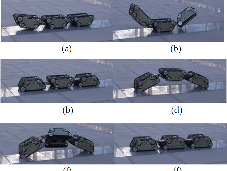
It is possible for the robot to implement a 90° recovering movement by adopting the proper configuration sequence, as shown in Fig. 12.
The robot is lying on its side. The first module and the last module are yawing up around the X axes of the active joints. Then the first module and the last module are rotating 90° around the Z axes. After that, they are pitching down around the Y axes of the active joints until they are attached to the ground in order to raise the middle module up. The middle module is rotating around the Z axis until it is parallel to the ground. In the end, the module is pitching down around the Y axes of the active joints until all three modules attach to the ground together. The robot is now in its home state again, and the process of 90° self-recovery is over.

The 90° recovering movement
It is also possible for the robot to tip over and realize the 180° recovery movement as shown in Fig. 13.
The robot is in its home state. The first and the last modules are pitching up around the Y axes of the active joints until they are in the air. The first and the last modules rotate 180° according to the Z axis. Then they pitch down around the Y axes of the active joints until both of them attach to the ground. The first and the last modules are pitching down around the Y axes of the active joints until the middle module is in the air. The middle module rotates 180° according to the Z axis. Then the middle module is pitching down around the Y axes of the active joint again until all three modules attach to the ground. The process of 180° self-recovery is over.
The 180° recovering movement
In contrast to conventional theoretical research, the project introduced in this paper successfully completes the following innovative work:
It proposes a robot named JL-I which is based on a module reconfiguration concept. The robot features a docking mechanism with which the modules (as shown in Fig. 14) can connect or disconnect flexibly. The active spherical joints formed by serial and parallel mechanisms endow the robot with the ability of changing shapes in three dimensions. A kinematics model of reconfiguration between two modules is given. The relationship of the world coordinate and the reference joint coordinate is concluded. The movement can be anticipated according to the joints' driving outputs. Experimental tests have shown that the JL-I can implement a series of various reconfigurations. This implies the mechanical feasibility, the rationality of the analysis and the outstanding movement adaptability of the robot. The performance specifications of JL-I are given in Table 1.

The distributed module
Performance specifications

Actually all of the locomotion capabilities are preprogrammed at the moment. In future, our research will focus on the realization of real autonomy. At the same time, the dynamic analysis of the movement functions is another important issue in this project.