
Abstract
This article deals with the analysis of geometric deviations influence on in-pipe robot locomotion, which uses the principle of friction difference principle. Bristles are as carrying elements. They are mounted as cantilever beams at angle to robot body. The robot should locomote inside industrial pipelines. All pipes have geometric deviations, which come from production process otherwise from operation process. It is necessary to know about the influence of these geometric deviations on the robot locomotion.
Keywords
Introduction
In-pipe robot is a device that is frequently used for inspection tasks or cable drawing into pipes. 1 –21 The main goal of this work is to identify the influence of geometric pipe deviations on in-pipe robot locomotion. The in-pipe robot analyzed is based on the friction difference principle (Figure 1). Contact with the pipe wall is ensured with bristles attached in two groups located in front and back part of the robot. Bristles are elastic cantilever beams attached at angle in respect of the robot body axes.
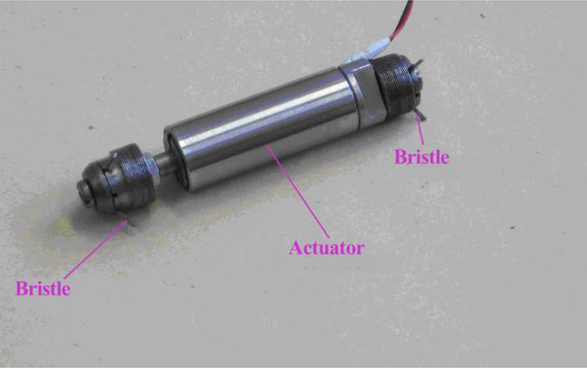
Bristled in-pipe robot.
Mounting span of free end of bristles is bigger than the inner pipe diameter (Figure 2). It means that bristles are deformed after inserting the robot into pipe. Deformation is defined with rigid inner pipe wall diameter and its geometric deviations. The problem is to identify the influence of these geometric deviations on robot locomotion.

Bristle mounting.
All referred studies 1 –7 solve in-pipe robot or machine, but research on suitable bristle configuration is missing. For this reason, there are several novel points in this article. This article brings the research of geometric deviation influence on the normal force between bristle tip and inner pipe wall. The normal force has direct impact on locomotion velocity and traction force of in-pipe robot. The article also brings math model of normal force, which can be used for simulation and optimization of bristle geometry. The main aim is to obtain the maximum velocity and traction force of in-pipe robot.
Bristle mounting and its deformation
Normal force between bristle tip and inner pipe wall is a result of bristle deformation forced from the difference between mounting bristle span and inner pipe diameter. Another important fact is that bristles are attached diagonally at angle. The diagonal bristle mounting is derived from previous analysis and experimental results . This bristle slope causes friction difference between friction force generated in forward and backward locomotion. Motion of the robot body is towards left or vice versa, but result locomotion is forward (left, Figure 2). The aim is to design this robot configuration with maximum friction in backward direction and minimum friction in forward direction or moving to the left side should be easier than moving to right side.
Geometric deviation of inner pipe wall is derived from various sources such as production process and sediments from pipe using deformation caused from assembly process of pipeline. In the worst case, geometric deviation can change the place of bristle contact and the bristle active length. This situation probably affects locomotion troubles.
Deformation can be described and analyzed as shown in Figure 3. Input parameters are length of bristle L S, mounting angle α 1, and displacement r p of bristle free end after inserting into pipe. It is necessary to identify the dependence of bristle deflection y on bristle free end displacement r p after inserting the robot into pipe.
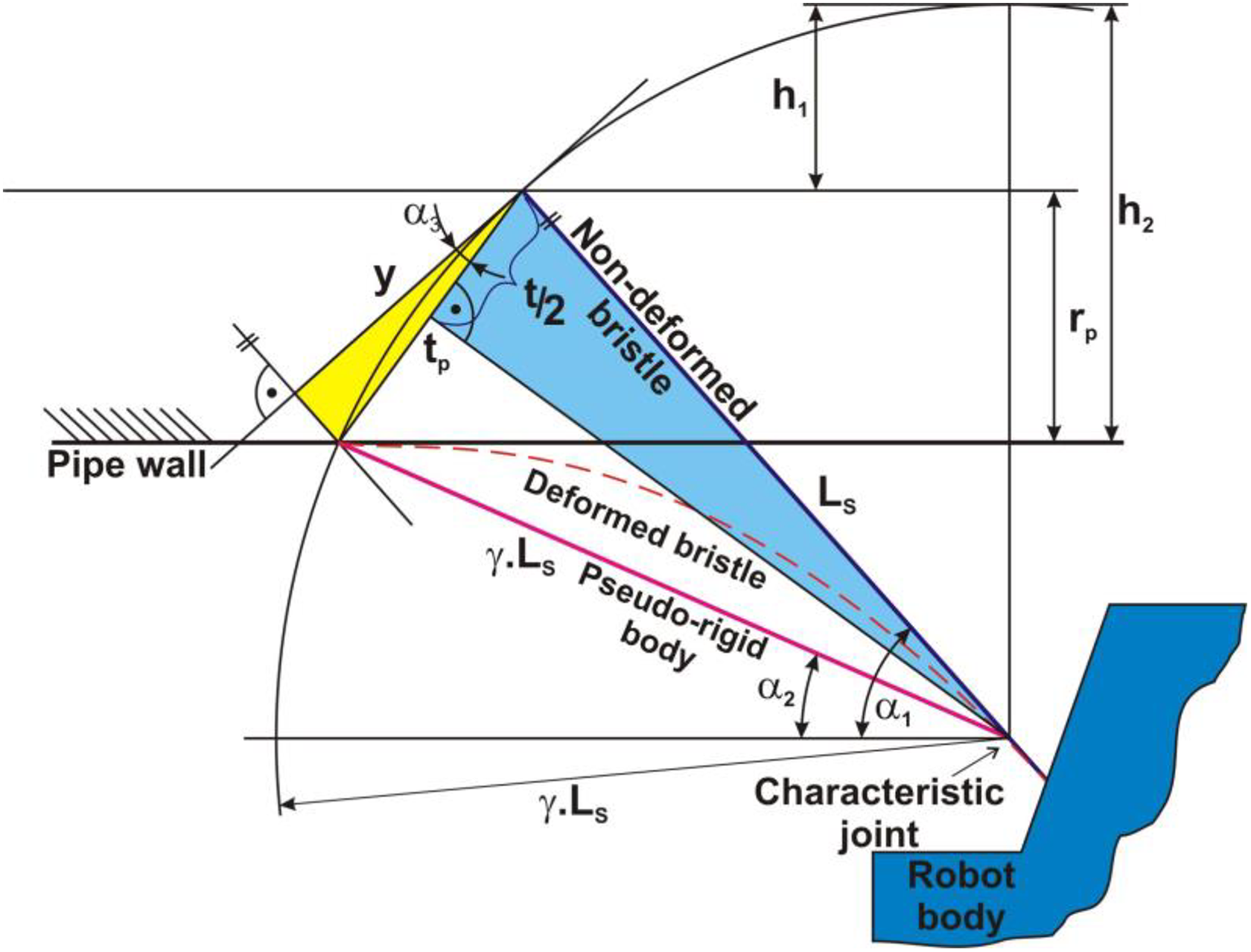
Bristle deformation after inserting the robot inside the pipe.
On the basis of analysis in Figure 3, it is possible to obtain the equation that describes bristle deflection

where L S is the length of bristle, γ the factor of characteristic radius, α 1 the mounting angle of bristle, and r P the displacement of bristle end
Analysis of force situation on loaded bristle
Normal force F N between bristle tip and inner pipe wall is generated after inserting the bristled robot into pipe. Also, friction force F T is deviated from the normal force and friction coefficient. If the bristle is moving back against the bristle declination, then axial force F B causes additional loading of bristle. Force situation also depends on deflection curve.
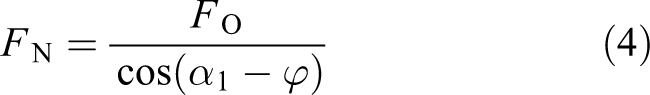
Final bending moment is caused by transversal force F O and axial force F B. It is possible to derive from Figure 4, the equations for these forces


where φ is the inclination angle of deflection curve and α 1 is the mounting angle of bristle. For normal force F N, the equation follows

Force situations for standing robot in horizontal direction.
Transversal force F O and the inclination angle φ of the deflection curve are unknown quantities. Transversal force F O is a function of bristle stiffness and stiffness is a function of bristle length. Inclination angle φ of deflection curve is a function of bristle deflection.
Identification of bristle stiffness as a function of bristle length
The main goal is to experimentally identify the function of bristle stiffness on bristle length. The dependence between the bristle stiffness and bristle length is possible to identify using experimental mapping of deflection trajectory of bristle body. Bristles are made from EN 1.0600—ASTM A228/A228M-14 with a circular cross section of 0.3 mm diameter. This bristle type has been also used for experiments. Various bristle lengths have been used for obtaining dependence between the bristle stiffness k S and bristle length L S (Figure 5).

Dependence of the bristle stiffness on its length for bristle (EN 1.0600) with circular cross section (Ø 0.3 mm) with various lengths in range from 5 to 25 mm.
Obtained dependence (Figure 5) can be approximated with exponential math model

Identification of dependence between inclination angle of deflection curve and bristle deflection
The main goal is to identify dependence between the inclination angle of deflection curve and the bristle deflection. Experimental mapping of deflection trajectory of bristle body also gives the information about inclination angle of deflection curve in the end point of bristle and bristle deflection for various materials with the same bristle length (Figure 6).
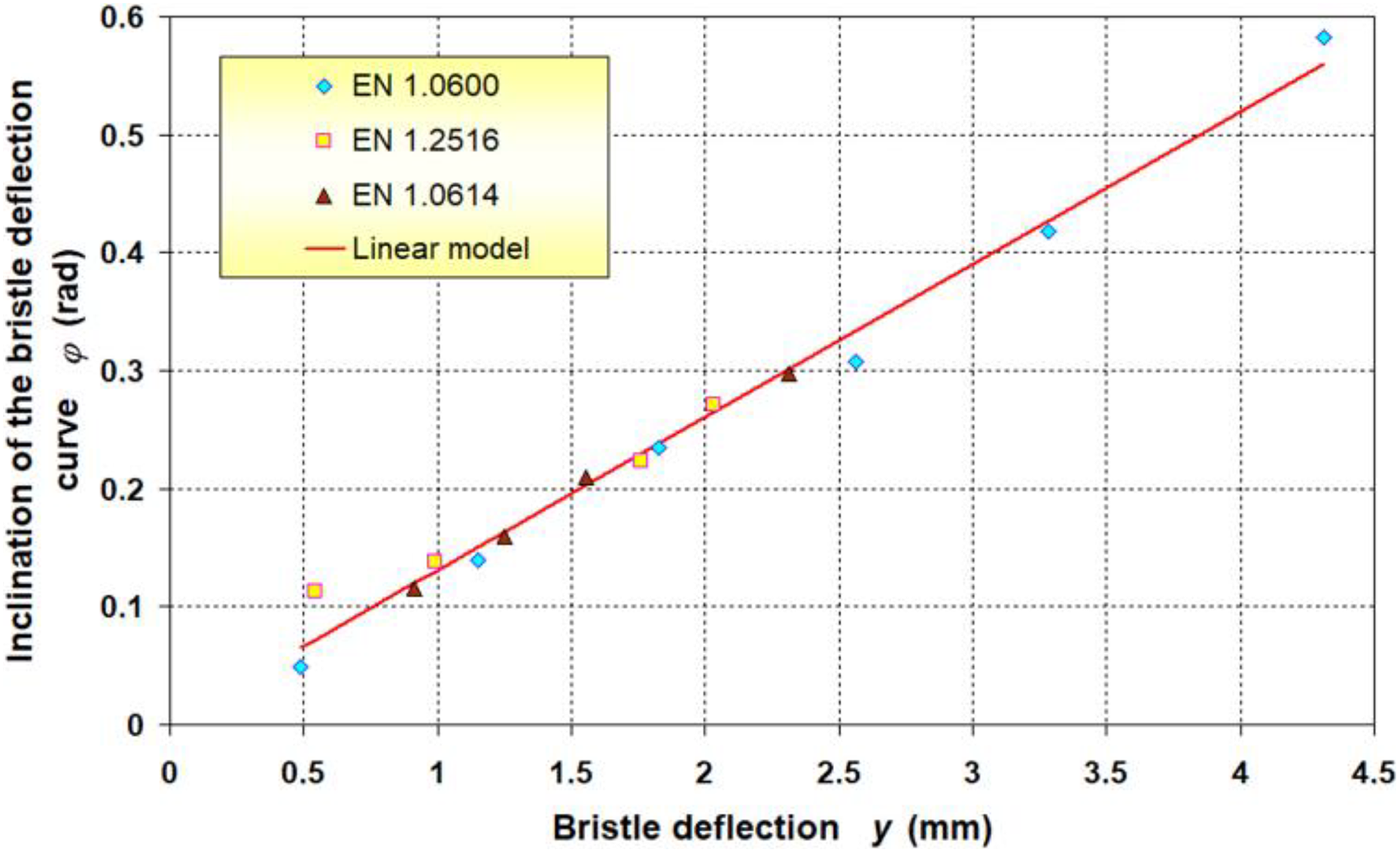
Dependence between the inclination angle of the bristle deflection curve in its end point on its deflection for various bristle materials (for a constant bristle length L S = 10 mm).
Results of regression give linear math model described with equation

where a Fi is the coefficient dependent on bristle length and this term is also defined as “length coefficient” in the following texts.
Next task is to identify the function between the length coefficient a Fi and bristle length L S. Experimental mapping of deflection trajectory of bristle body also can be used for obtaining the function. Length coefficients have been obtained for bristle made from EN 1.0600 at various lengths in the range from 5 to 25 mm. Length coefficients are the deflection y multiplier (slope of line) of regression equations shown in Figure 7.

Dependence of the bristle inclination angle on its deflection for various bristle lengths from material EN 1.0600.
Dependence between the length coefficient a Fi and bristle length L S shown in Figure 7 can be summarized as the function shown in Figure 8.
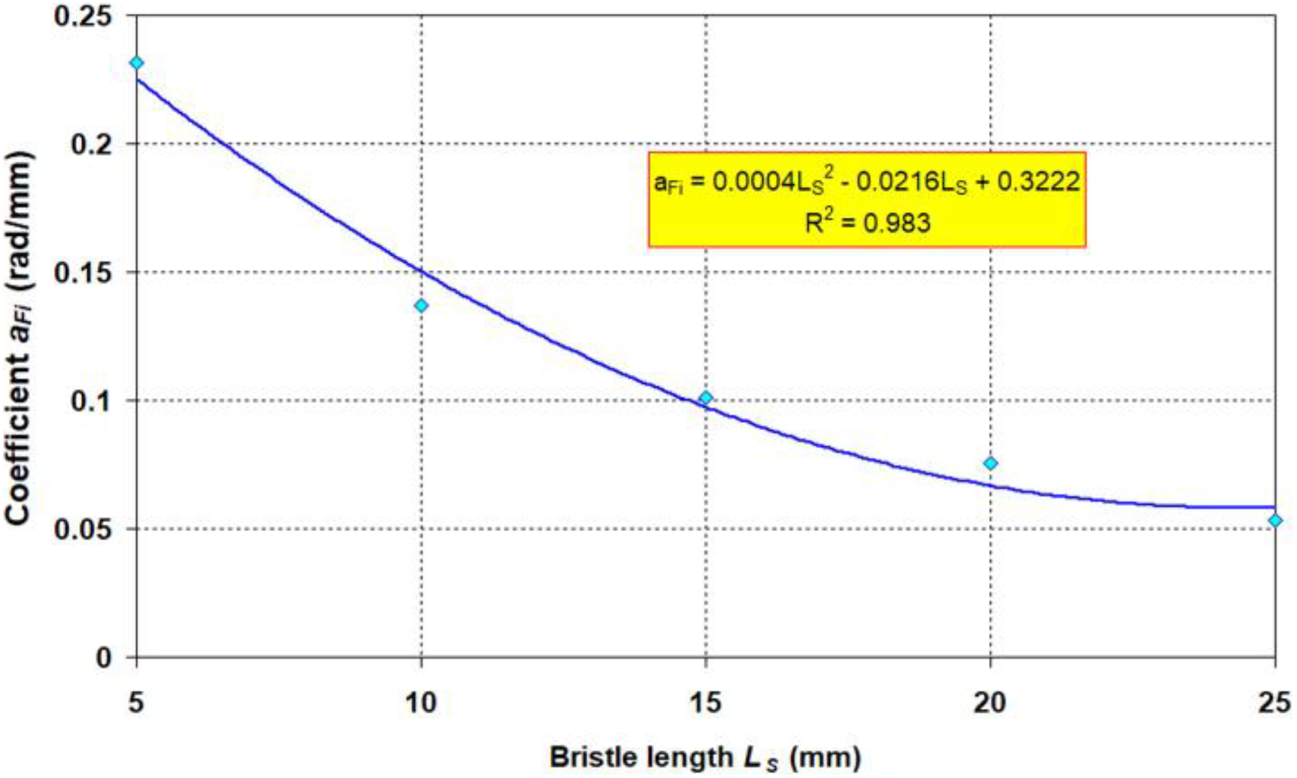
Dependence of the length coefficient a Fi on bristle length L S for various bristle lengths from material EN 1.0600.
Math model of length coefficient a Fi can be obtained as polynomial function

After substituting equations (5) to (7) in equation (1), the equation for normal force F N can be obtained
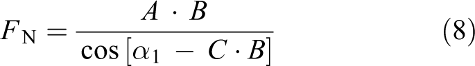
where coefficients A, B, and C are given as


Equation (8) shows that, normal force F
N is a function of three variables: bristle mounting angle; bristle length L
S; and displacement of free end of bristle r
P.
Consequently, normal force can be adjusted via using of one of above-mentioned variables.
Figures 9 to 15 show dependence of normal force on mounting angle and displacement of free end of bristle (bristle length L S = 10 mm is in accordance with the math model in equation (8)).

Dependence of the normal force on bristle assembly angle and free bristle tip displacement in case of bristle length 10 mm.
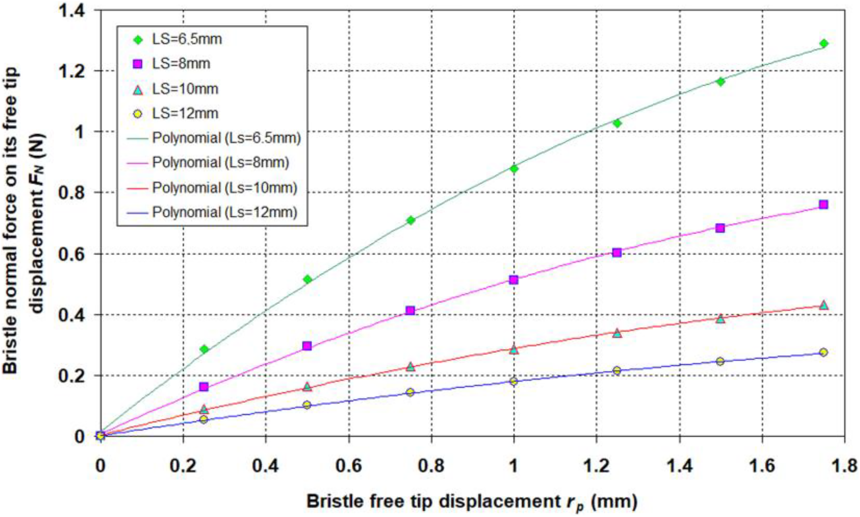
Dependence of the bristle normal force on their free tip displacement (for assembly angle α 1 = 50°).

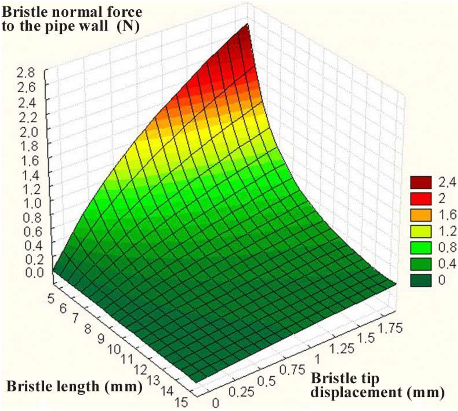
Dependence of the bristle normal force to the pipe wall on bristle length (for bristle assembly angle α 1 = 10°).

Dependence of the bristle normal force to the pipe wall on bristle length (for bristle assembly angle α 1 = 10°) spatial visualization.
Dependence of the bristle normal force to the pipe wall on bristle length (for bristle assembly angle α 1 = 25°) 3D visualization.

Dependence of the bristle normal force to the pipe wall on bristle length (for bristle assembly angle α 1 = 35°) spatial visualization.
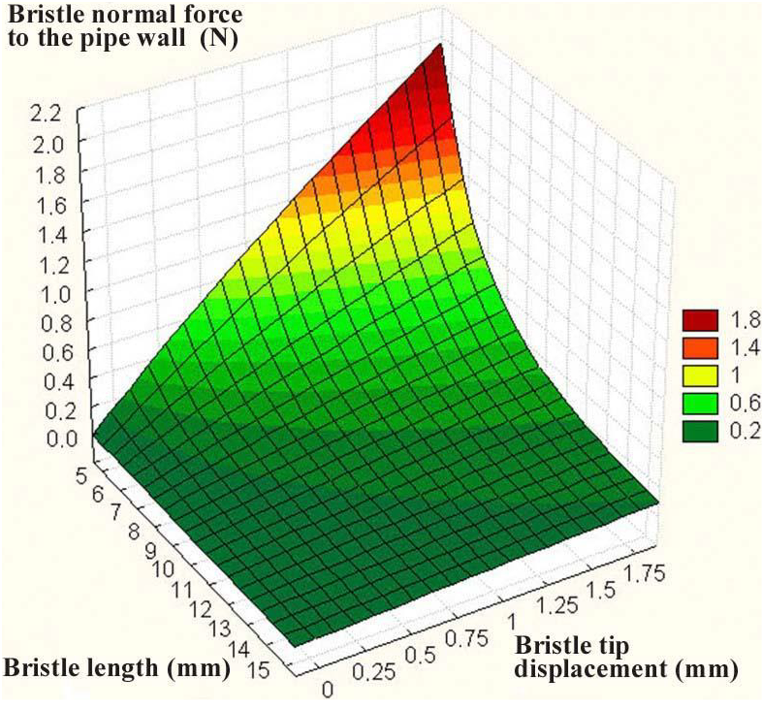
Dependence of the bristle normal force to the pipe wall on bristle length (for bristle assembly angle α 1 = 50°) spatial visualization.
Investigation of sensitivity of characteristic function, that is, math model of normal force (equation (9)) is understood as change of behavior of normal force F N caused by parameters of its structures in general form. It leads to complicated forms of partial sensitivities. From these sensitivities, it is very complicated to identify which parameter is more suitable to change from the viewpoint of elimination of the influence of inner pipe surface geometric deviations on normal bristle force. One possible solution is to choose concrete working area and to evaluate only local sensitivity of system, that is, only in the selected working area.
Conclusion
Normal force is more sensitive to change of free bristle tip displacement, when montage angle is increased (Figure 9). Figure 10 shows that normal force of bristle is more sensitive to shorter bristle length for montage angle α 1 = 50°. It means that the influence of change of bristle tip displacement, that is, the influence of inner pipe wall deviations on normal force of passive bristle can be eliminated through enlarging the bristle’s free tip length.
Figure 2 shows that interaction between bristle and inner pipe wall causes the change of contact place between the bristle tip and the inner pipe wall. It means that active length of bristle also varies and for this reason bristle stiffness also varies. This effect has direct influence on the value of normal force between the bristle tip and inner pipe wall. Figure 11 shows the influence of normal force F N on the change of bristle length and change of bristle tip displacement. Influence of bristle length is stronger for smaller montage angles (Figures 11 to 15).
From all the above mentioned, it is possible to confirm that longer free end of bristle is the best way to eliminate the influence of geometric deviations on normal force and also traction force of the in-pipe robot.
On the basis of the above analysis, an experimental in-pipe robot has been made as a result of cooperation with other university (Figure 16). Future plan is to make next experimental works with this model. The first experimental results show that locomotion properties depend on geometric pipe deviations and also on quality of inner pipe surface.

Adjustable bristled in-pipe robot.
Next research will be focused on developing suitable actuator. Another way to improve robot properties is to make “active bristles,” which will change their properties with the aim to improve locomotion properties of the in-pipe robot. Application of smart elements for improving robot performance is also used in different mechatronic systems. 22 –25
Footnotes
Declaration of conflicting interests
The author(s) declared no potential conflicts of interest with respect to the research, authorship, and/or publication of this article.
Funding
The author(s) disclosed receipt of the following financial support for the research, authorship, and/or publication of this article: The authors would like to thank the Slovak Grant Agency—project VEGA 1/0872/16 financed by the Slovak Ministry of Education. This contribution is also the result of the project implementation: Centre for research of control of technical, environmental, and human risks for permanent development of production and products in mechanical engineering (ITMS: 26220120060) supported by the Research & Development Operational Programme funded by the ERDF.