
Abstract
The in-pipe machine locomotes in the pipe on the principle of differential friction between the bristles and the pipe wall during the movement of the bristle forwards and backwards. These bristles are very important construction parts of the in-pipe machine. In order to define the locomotion of movement it is important to know the force situation on the bristles caused by its high deformation in the pipe. The determination of force situation brought us to a non-linear differential equation of the second order and determination of conditions for its solution. By this equation it is possible to describe the outline of large deformations of the construction part and to determine the forces affecting this part.
Introduction
Within an industrial setting, extensive and complex pipe systems exist that can be used for ducting liquids or suspensions or as protective devices for other systems. Such pipe devices are included in nuclear power station equipment (heat exchangers), chemical plants and aviation equipment.
Several factors adversely affect both the condition and the operating life of a pipe. The substances ducted through the pipe are often dangerous, and any leak may cause a disaster. The consequences of such a disaster may be extensive and its nature may be irreversible. To avoid disaster, a pipe must be periodically screened to detect leakage and other defects. Early warning is an important element of disaster prevention.
Interior pipe inspection to detect defects in the pipe is regarded as the most objective method available. As an example, inspecting the pipe system (the steam generator) of a nuclear power station is very difficult from outside of the pipe. Pipe inspection is the main reason for the rapid development of in-pipe machines [1].
State of the art in area of in-pipe inspection devices
In-pipe devices use various type of locomotion. All of them can be sorted into two main groups:
Synthetic types (wheeled type, tracked type, pig type). Biologically inspired types (swimming type, inchworm type, snake-like and earthworm-like type, walking type, bristled inertial type, and bristled anisotropic friction type).
The wall-pressed wheeled type is the most popular main locomotion system in in-pipe robot development.
Inspection robot for 1–in pipes has been developed. The robot is 23 mm in diameter and 110 mm in length and is equipped with a high-quality micro charge-coupled device (CCD) camera and a dual hand for manipulating small objects in pipes [2].
Most famous wheeled in-pipe robots have been developed by Hirose Lab for inner pipe diameters 25 mm, 50 mm and 150 mm [3].
An in-pipe wheeled robot with active pipe-diameter adaptability and automatic tractive force adjusting has been developed for long-distance inspection of main gas pipelines with different diameter series (from 400 mm to 650 mm) [4].
A novel untethered autonomous motor driven in-pipe wheeled robot inspecting system has been designed in order to solve the internal defect inspection for a long-distance pipeline. Including a motor-driven traction robot and other multiple cylindrical box modular units, the adjacent units are linked by double hook joints and by three extended supporting wheels contacting the inner surface of pipe elastically to form the articulated multi-body system [5].
Novel new design and simple locomotion strategies have been designed for a pipe inspection robot that can travel through various pipe configurations including vertical, elbow, and branch pipes. Two specific mechanisms in the robot are important for successful locomotion: the adaptable quad arm mechanism (AQAM) and the swivel hand mechanism (SHM). The AQAM allows the robot to travel in reduced branch pipes and branch pipes with a zero-radius of curvature, which are both common in real life but which pose a challenge to the previously developed in-pipe robots. The SHM enables the robot to change its orientation, and, in particular, allows it to bypass bumps. [6].
In-pipe inspection robots with hybrid locomotion have been developed. Hybrid locomotion combines two or more propulsion mechanisms in achieving a robust but yet flexible robot platform [7]. The hybrid design is basically a wall pressing helical type which is simple in electromechanical design, yet provides adequate mobility within a relatively small space constrained by pipes [8], [9].
There are also helical (screw) path type wheeled in-pipe robots. Several proposed types have driving wheels that are tilted an angle. When forced to rotate against the pipe wall, the driving wheels will follow a helical path, thereby generating a thrust force along the pipe axial direction. The thrust force is the locomotive force for the mechanism/robot [10], [11].
A caterpillar track gives greater advantage in preventing a motion singularity problem while surpassing branches. On the other hand, the wheeled wall-pressed type provides an advantage for high-speed mobility. FAMPER has four caterpillar tracks that provide good gripping force in both vertical and horizontal pipeline situations. Independent suspensions and links enable FAMPER to travel in any type of pipeline network available [12].
Pig type inspection uses inspection device called as “pig”. Pig is equipped with 16 ultrasonic transducers, on-board energy systems and acquisition and data storage systems. It is developed for inspection of oil pipelines with diameters ranging from 200 to 500 mm [13].
An in-pipe wireless swimming microrobot has been developed, whose caudal fin is fabricated by a GMF (giant magnetostrictive thin film) microactuator. These micro-fish-like robots exhibit good swimming performances for underwater operations. However, there are some problems for the above microrobots, such as leaking electric current, and safety in water, especially driving with long cables or batteries, which will result in some difficulties in the further application of microoperation in small and complex spaces [14], [15].
A lot of work on inchworm in-pipe drives has been reported in previous years. Most drive designs have three distinctive modules: a clamping module, a linkage module, and an extension/retraction module [16], [17], [18].
By using only one pneumatic line, an inchworm-like micro robot for pipe inspection is invented. It enables the robot not only to generate inchworm-like locomotion, but also to allow significant reduction of the stiffness of pneumatic lines and the drag force due to one pneumatic line. In addition, a micro robot with a diameter of 10 mm could be accomplished owing to its simple chamber structure. In order to operate the robot efficiently, the stroke according to the supplied pneumatic pressure is investigated [19].
A novel biomimetic earthworm-like micro robot with wireless control and a wireless power supply using a shape memory alloy (SMA) actuator has been developed. The SMA actuator and bellow play roles in the contraction and extension of an earthworm muscle, respectively [20].
Snake-like and earthworm-like robots for inspection inside pipes were also developed [21]. A snake-like robot needs many degrees of freedom. Mechatronic systems that have many degrees of freedom such as the robot require a decrease in the number of wirings, high tolerance for electrical noises, and high performance by decentration processing. Each link contains an intelligent actuator equipped with sensors and a micro CPU that has a communication function between the actuator and a host controller [22].
In the next laboratory an earthworm-like peristaltic crawling in-pipe robot with pneumatic artificial muscles has been developed for use in 1-in gas pipes. This robot can pass through a 90-degree elbow in the horizontal and vertical planes. In addition, this robot can be equipped with an endoscope and take videos inside a pipe. However, it has been unable to pass through continuous elbows, which are occasionally encountered [23].
The walking type TUM pipe crawling robot supports itself with at least four legs contacting the tube walls. Each leg has two actuated joints; hence the robot is controlled using at least eight actuators. The force distribution problem is therefore statically indeterminate: for any kinematic stance of the robot, there exist an infinite number of foot force distributions (or, correspondingly, actuator torque combinations) that satisfy the equations of equilibrium [24], [25].
The bristled in-pipe robot uses various types of contact elastic elements as bristle or fin. These robots use two various locomotion principles. Vibration types of bristled in-pipe robots use an inertial (impact drive moment) locomotion principle generated via the use of an electromagnetic actuator [26] or piezoelectric actuator [27], [28]. This locomotion principle is also known via the use of a magnetostrictive alloy [29].
The next paper presents the study of a pipeline robot based on a bristle mechanism for a pipe with an inner diameter between the ranges of 9 to 15-in. The bristle mechanism shows great flexibility and makes enables the pipeline robot to be able to work in ill-constraint pipes, which were previously considered as unpiggable or uninspectable. A bristle traction force model is set up and the approximate calculation of bristle traction force based on Euler buckling theory is also described [30].
The bristled micromachine locomotion is based on the inertial stepping principle, which utilizes the drive force of the two-body impact. The in-pipe micromachine contacts the pipe through the elastic bristles installed on the in-pipe machine and in two lines and crossways with respect to the micromachine axle [31].
Only a handful of in-pipe robots have been designed for a pipe with an inner diameter of less than 25 mm. This paper contains an analysis of a bristled in-pipe machine that locomotes via the use of bristles attached at an angle to a machine body. The principle of locomotion is based on anisotropic friction between bristle tip and an inner pipe wall.
Definition problems occur in this area, because various terms have been used for this inspection tool as an:
in-pipe robot; in-pipe machine; in-pipe mechanism; in-pipe vehicle; in-pipe crawler, etc.
We have decided to use term ‘machine’ in the next section.
Principle of in-pipe machine locomotion
The proposed in-pipe machine is planned for a pipe with an inner diameter less than 25 mm. The first functional model has been developed for a pipe with an inner pipe diameter of 11 mm (overall length was 35 mm). The machine was actuated via the use of low-voltage piezo-stack. This machine has several problems with locomotion (loss of contact with pipe wall, and blocking of machine inside pipe). For this reason this study has been implemented.
The simplified scheme of a miniature in-pipe machine is shown in figure 1. It consists of the linear actuator and the system of two groups of bristles (front and rear). The bristles are distributed equally around the machine and are tightened diagonally under an acute angle towards the axis of machine. The actuator generates the stroke, i.e., the mechanical displacement at specific force. By generation of this displacement the mutual distance of both groups of bristles is changed. Diagonal tightening of the bristles causes anisotropic friction, i.e., the difference of frictional forces between the ends of bristles and the inner wall of the pipe during the movement forwards and backwards. Exactly this difference of friction will cause the final forward locomotion of an in-pipe machine [28].

Locomotion principle of the miniature mobile in-pipe machine
The key benefit and novelty of an in-pipe machine is its better ability to locomote inside the pipe. This principle has no tendency to slip like wheeled machines.
The basic task of design of an in-pipe machine is locomotion. Forward locomotion is enabled by passive resistances of bristles on the inner pipe wall. Force situation is determined by deformed bristles in a closed rigid space. It is necessary to know this force situation for the determination of frictional forces between the bristle and the pipe wall.
The movement in the pipe presumes large bristle deformation (more than 25% of bristle length). Therefore, in this solution it was necessary to apply the theory of large deformations, and for this case to compose equations describing the outline of large but elastic deformations (figure 2).

Outline of large deformation
For this purpose we chose the prismatic shape of bristles of a round cross-section and such material, which allowed a large deformation. The deformations were caused by the insertion of an in-pipe machine into the pipe with an inner radius r2 (figure 3), in which the inspection was performed. To be able to determine the properties of an in-pipe machine, it was necessary to know the forces that caused this deformation. The curve outline, describing large deformations, brought us to the creation of a non-linear differential equation, by the solution of which we determined the forces affecting the bristles.

Deformed bristle in pipe
A mathematical model representing the outline of large deformation was created for the case of loading of the construction part according to figure 2. In general point
where
Change of curvature 1/ρ, related with moment (1), can be expressed as follows:
where R is original radius of curvature, and E is Young's modulus of material elasticity of bristle, which was determined by experimental tensile test, and
If the curvature 1/ρ is expressed in general form:

then after the introduction of further dimensionless parameters p2=Fl2/EJ, substitution of equation (2) into equation (3) and by its derivation we gain a non-linear differential equation of the second order describing the outline of the elastic deformation of the very curved construction part:

where s is length of considered outline and l is the total length of this part.
The following functional dependency is valid for the angle of deflection (slope) φ:

Equation (4) was applied for a specific case of a deformed outline of the construction part according to figure 3. In figure 3, symbol δr represents the deformation of the bristle and angle β (mounting angle) the inclination of the bristle from the axis of the pipe before deformation.
Equation (4) can be easily integrated, but this brought us to elliptical integrals, so we used the method of Runge Kutta for a solution. The results of the measurements (figure 4, 5) and calculations are interpreted in the enclosed charts (figure 6–10).

Measuring device for experimental determination of the outline of the deformed bristle (1 – bristle, 2 – force sensor, 3 – clamp jig, 4 – XY table)

Clamping of bristle in measuring device
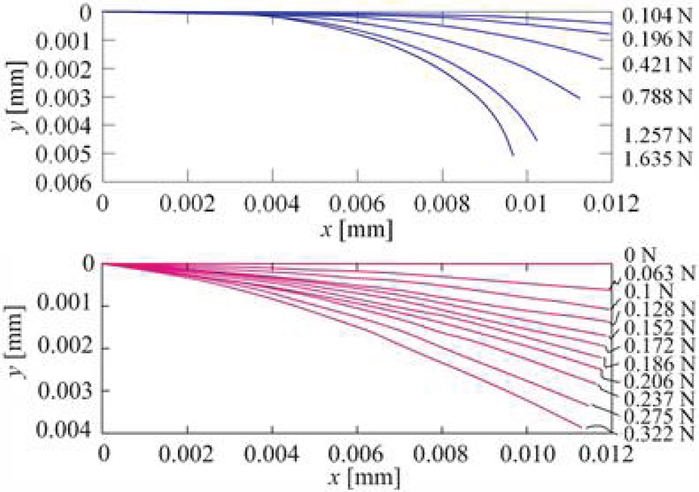
Calculated outline (top figure) and experimentally determined outline (bottom) of deformed bristle
Coordinates of endpoint of bristle

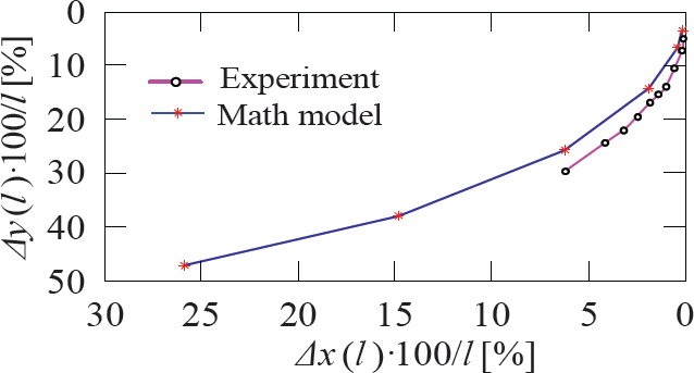
Position of endpoint x depending on loading by force F

Position of endpoint y depending on loading by force F

Angle of deflection (slope) of cross-section φ depending on loading by force F
The results of the calculation were verified experimentally on measuring equipment consisting of an XY table and profile projector for recording the outline of the deformed bristle (figure. 4). The force of the bristle in its endpoint was measured in a direction perpendicular to a non-deformed cross-section of the bristle by a force sensor (figure. 5).
Clamping of the bristle was realized in a clamp jig on the XY table (figure. 5). The force sensor at the endpoint of that bristle was before measurement calibrated by a set of etalon weights in order to verify the functionality of the force sensor.
In figure 6 deformations of the bristle caused by insertion into the pipe are represented, and simultaneously the force of the bristle is given, which was induced by insertion of the bristle into pipe. In figure 7 the percentage coordinates of the endpoint of the bristle for the rising magnitude of loading force are given. Further charts (figure 8, 9, 10) show the position of the endpoint Δx(l), Δy(l), or the angular displacement of the cross-section φ(l) of the endpoint depending on the detected force F.
By decomposition of force F we determined its normal and tangential component. For these the Coulomb relationships

where for index 1 means movement forward and index 2 movement backward.
The reaction of the pipe wall on bristle is:

From equation (6) it is valid that friction force
In order to fulfill the consideration given above, it is complicated in practice to influence the coefficient of sliding friction, and therefore from a practical point of view the maximal difference of sliding forces at movement forward and backward is chosen as the criterion. Equation (6) does not contain information about the influence of the speed of the machine on friction force [6–13], and it can therefore be adjusted to the form:

where
These equations (6, 7, 8) were used for the creation of a model of an in-pipe machine. The numerical calculation block for the mathematical model of the bristle (equation 4) was included into a simulation model of an in-pipe machine (figure 11). The simulation model was created using Matlab/Simulink software.
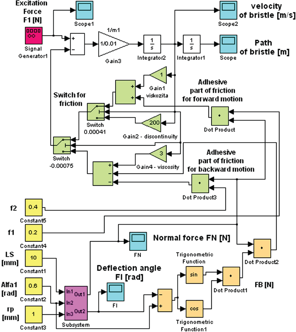
Simulation model of in-pipe machine
It is possible to use this simulation model for simulation experiments and exploring properties of an in-pipe machine. The results of these simulations will be used for designing an in-pipe machine with the goal of reaching the maximum speed of locomotion of the machine in pipe.
For the verification of the correctness of the simulation model the in-pipe machine was built with adjustable bristles (figure 12).

In-pipe machine with adjustable bristle geometry
The in-pipe machine allows the setting of the length of the free end of the bristle, assembly angle of the bristle, and the distance of the clamping of the bristle from the axis of the machine. This functional model of an in-pipe machine allows verification of the obtained simulation model, which then enables the subsequent optimization of bristle geometry from the viewpoint of achieving a maximum steady velocity of locomotion and traction force of the in-pipe machine.
Simulation results show the machine's behaviour for various input parameters (body size, bristle geometry, different actuator, etc.). All received simulations show the ways in which the machine can be optimized.
Experiments with this functional model of in-pipe machine were realized by drawing etalon weight (figure 13).

Experiments with in-pipe machines with adjustable bristle geometry
The problem in these experiments is a relatively large dispersion of measured values of the speed of machine locomotion caused by geometric deviations of the inner surface of pipe. Specifically, such simulation models allow the realization of simulation experiments under the same conditions, and assure good repeatability of the experiments. Simulation experiments are not so demanding of time as experiments with functional models. Moreover, the simulation model also allows the exploration of extreme situations, which could not be realized at experiments with functional models.
Figure 14 shows the results of simulations and the results of experiments with a functional model of an in-pipe machine under constant geometric parameters of bristle (length of free end of bristle, assembly angle of bristle).

Results of simulations and experiments with functional model of in-pipe machine at locomotion in horizontal pipe with constant geometric parameters of bristle
These results confirm the correctness of the simulation model of the bristle of an in-pipe machine. The difference between the mathematical model and experiment is caused by geometric deviations of the inner pipe wall (deviations of nominal dimension of inner pipe diameter, shape deviations of pipe, roughness of surface).
The existence of these deviations has a stochastic character and it is therefore not possible to describe exactly their influence and integrate them into mathematical and simulation models of an in-pipe machine.
The obtained simulation model is appropriate for the simulation experiments and the optimisation of the bristle geometry of an in-pipe machine.
The value of bristle deformation directly influences the normal force Fn, and from it the resulting friction force F t , therefore finally also affecting the resulting velocity and traction force of the in-pipe machine, which is confirmed by experiments on the functional model of an in-pipe machine. These experiments simultaneously confirmed the correctness of application of differential equations in solutions of large deformations of the bristle of an in-pipe machine. The contribution of this simulation model is mainly the fact that for specific dimensions of the pipe it is then possible with the help of this simulation model to find the optimal geometry of the bristles of in-pipe machines. It is also possible to apply the solution of large deflections of the bristle for other cases of large deformations of construction parts [29–31].
The simulation model can also be easy modified for locomotion in vertical pipes, with the addition of gravitational force. The main contribution of this work is obtaining a simulation model, which gives us the possibility of studying in-pipe machine properties in terms of dependence on body size, geometry of bristles, actuator, pipe deviations, etc. The simulation model has been verified with the experimental model (figure 12). These results enable us to continue this research and we currently continue with the optimisation of the in-pipe machine.
Footnotes
9.
The work has been accomplished under research project nos. VEGA 1/1205/12, KEGA 048TUKE-4/2014 and APVV-0091-11 financed by the Ministry of Education. This contribution is also the result of the project implementation: Research of modules for intelligent robotic systems (ITMS: 26220220141) supported by the Research & Development Operational Programme funded by the ERDF.