
Abstract
Model-mediated teleoperation has been developed to improve both transparency and stability in teleoperation. It uses local model of remote environment to provide non-delayed force feedback rather than using delayed force signals from slave side and thus is robust to arbitrary time delay. However, updating parameters in the local model may cause sudden force change during the operation. Meanwhile, the undesirable deep penetration or overlarge contact force may occur on the slave side due to the modeling error. Both of them will jeopardize the system stability. In this article, we propose a novel force-based model updating algorithm, which restrains the abrupt force caused by parameter updating. The update efficiency has been greatly improved by comparing with the existing solution; meanwhile, it ensures a stable human–machine interaction at the same time. Then, a new adaptive impedance controller that restricts both overlarge force and penetration is introduced. The obtained results on a one-degree of freedom contact experiment with a delay of 5 s demonstrate the superiority of proposed approaches in comparison with state-of-the-art methods.
Introduction
Robotic teleoperation system enables operators get a presence perception of interaction with remote environment where human presence is hazardous or costly. To this end, one critical step is the force feedback that gives the operator the perception of the force exerted by the slave manipulator. 1 However, the force feedback could be out of phase compared to operators command due to the delay in telecommunication system and it has been recognized for many years that even a small time delay in the control loop may jeopardize the stability and performance. Although the stability can be achieved by more conservative control strategy, for example, passivity-based schemes, the transparency will be significantly decreased. 2 Considerable effort has been made to deal with the trade-off between stability and transparency. The mainstream techniques adopted include four-channel architecture, 3,4 wave variable method, 5,6 and sliding mode control. 7,8 Despite these new improvements, there are still many tasks, which require a high degree of transparency under long time delay. But it is hardly to be realized by bidirectional teleoperation. 9
Furthermore, while many state-of-the-art researches assume a constant time delay, the time-varying delay and packet loss problems are particular challenges for both stability and transparency. 10 Therefore, alternative approaches that are less dependent on a high-performance communication network are becoming more and more desirable.
Model-mediated teleoperation (MMT) was proposed to improve both stability and transparency of teleoperation system. 11 The typical architecture of MMT is illustrated in Figure 1. On the master side, a model representing both geometric properties and contact dynamic properties of remote environment is built to be as accurate as possible. The user hand motion information is send to remote robot via a force-feedback device. Force feedback is provided based on the local virtual model of remote environment under negligible delay. On the slave side, the robot tracks the incoming commands while simultaneously collects sensor data (e.g. force, position, and image) for online estimating parameters of the model of the environment that it contacts. Rather than sending slave sensory data to the master side, estimated model parameters are transmitted back to master side under communication delay. Then, the parameters of the model on master side were updated according to the received parameters.

Structure of the MMT. MMT: model-mediated teleoperation.
The steady state in MMT is defined as the state that the estimated model parameters converge and the model mismatch error between the estimated model and real environment is neglectable. A transition state in MMT refers to a period that a model mismatch between local model and actual environment is existing. 12
Using estimated a model of remote environment, which include both geometric properties and contact dynamics, the operator could interact with local model rather than remote environment and thus could percept non-delayed force feedback. Theoretically, the teleoperation system can obtain ideal transparency in the presence of arbitrary time delay if the local model is identical with real remote environment. Different from conventional bilateral teleoperation algorithms, the MMT leads to the two subsystems and its stability condition is easy to meet. The study by Xu et al. 12 provides more details about MMT.
The application and extension of MMT have attracted much attention and its most problems are at least partly solved. MMT has been adopted in multi-operator multi-robot systems by the coordination of the master devices using one centralized variable position-based admittance controller. 13 Based on the traditional position and force sensors, vision sensor is also used to strengthen the prediction ability of MMT systems. 14 Interaction with moving object that is much more complicated than fixed object was realized, while the modeling of general moving object is still difficult. 15 For better overall performance, other teleoperation techniques such as virtual fixture were actively incorporated in MMT systems. 16 Some promising variants of MMT were also developed. 17,18
Two key components of MMT are the estimation and obtaining the model of the remote environment and designing the slave side controller. 19 Multiple degrees of freedom mass-spring models and finite element models are highly accurate for simulation of deformable object. But they are computationally prohibitive for teleoperation system. 20 The main environment models used in robotics research are spring model, linear Kelvin–Voigt model, and nonlinear Hunt–Crossley model, which is the result of a balance between complexity and accuracy. All of them enable user to percept the virtual object’s mechanical impedance to some extent, which is necessary for the haptic rendering on master side. 21
Meanwhile, it is usually difficult to model the remote environment accurately before operation tasks or even after. In order to obtain better approximation or keep pace with the changing environments, the parameters describing the local model are continuously estimated on slave side and transferred back to the master, which is referred to online parameter estimation. Different techniques in environment modeling and online parameter estimation had been extensively studied and compared. 22 –24
Then, the local model on master side is updated based on the estimated parameters, which is known as model updating. Special attention must be paid in this process as improper update schemes may lead to undesired motion and instability. When the data received from slave side trigger a sharp change of the model parameters, such as the stiffness and environment location, the force feedback may be changed accordingly. It is difficult for users to stabilize the master controller if the force changed suddenly. Thus, the abrupt changing force may disrupt the user’s operation and cause unsafety issue on slave side because the abnormal command also is transmitted to slave. The negative impact of the abrupt change of model parameter is referred to as “model jump effect.” 25 Different schemes were adopted to deal with this problem, but these approaches delayed the updating of model parameters or changed them in a limited rate in order to maintain the stability or passivity of the system. 26,27 There is an alternative approach, the user is informed by a small force impulse when model updating is needed. Then, the user must move the master end to a safe area to enable the update of the model parameters. This approach will interrupt the operation frequently.
The transition state of model updating can be defined as the period when the force rendered by the master device is different from the original one that is computed based on the received parameters directly. To provide force feedback accurately, the transition period should be as short as possible. However, in order to obtain a stable haptic rendering, a trade-off of between smooth force rendering and quick transition is preferred.
Another challenge of MMT is the slave controller. While tracking the delayed command from the master side, the command is often built on inaccurate information due to the error between local model and real environment. Two state-of-the-art control approaches for slave control in MMT are the switching position control/force control method and the relative tracking method. 12
In switching position/force control approach, the slave is position controlled in free space and force controlled while in contact with the environment. Thus, the slave is controlled to maintain same contact force as applied on the master side. However, while the stiffness of the remote environment is smaller than that of the local model, the slave end-effector will penetrate into the environment more than that on the master side. The overlarge penetration may cause damages to the environment.
The relative tracking method proposed in the study by Winck and Okamura 19 is a modified PD controller. Instead of tracking the absolute position on master side, the relative tracking method takes the mismatch position into account. Environment model information is also sent to the slave side. The aim of relative tracking is to make the slave to track the master position relative to the model and thus maintains the same penetration for the slave side and master side. Even though the relative tracking avoids the undesired penetration on the slave side, it is not capable to deal with the stiffness mismatch between the local model and remote environment. Once the stiffness mismatch exsits, the contact force is deviating and the overlarge force will jeopardize the operation safety.
In this article, we propose a simplified MMT system and address the stability problem of MMT by introducing a new model updating approach and an adaptive impedance controller. The proposed model updating approach limited the ‘abnormal’ force changing and ensured stable human–machine interaction on master side. The proposed controller is kind of a supervisory controller. In addition to position commands, the corresponding local model information is also sent over communication link to the slave side. The slave controller interprets the operator’s intention on the basis of corresponding master state. After the comparison between the expected model and the real environment, it carries out command from master in a conservative way to prevent from both overlarge force and penetration. The proposed impedance control approach enables the controller to adjust its behavior smoothly without switching among different states and maintains a compliant contact with the environment. Eventually, the proposed controller can limit overlarge force and penetration in the presence of both position uncertainty and stiffness uncertainty in the transition state. Meanwhile, accurate tracking of both position and force is achieved in the steady state, that is, the system tracking capability is not compromised evidently. Note that the accurate tracking of both position and force in steady state does not mean the controller is able to control the force and position simultaneously, it is the visualized description of the result that both force and position on slave side are following that of the master side.
Furthermore, we made some discussion on the limitation of existing position-dependent environment model 28 and proposed to use interpolation mechanism to estimate environment impedance in an unmeasured position prior to the contact happened. By incorporating the prior knowledge and available vision information, the method is expected to shorten the transition state in MMT and accelerate the parameter estimation.
The article is organized as follows. The environment modeling and identification are presented in section “Environment modeling and identification.” Section “Environment model updating algorithm” presents the proposed model updating strategy. The adaptive impedance controller is presented in section “Adaptive impedance controller.” Experimental setup and results are described in “Experiments” section. Section “Discussion and conclusions” provides a discussion about the extension of the environment model in MMT and concludes the article with a summary and outlook.
Environment modeling and identification
Environment modeling
We first have a quick review and discussion on several mainstream contact dynamic model in MMT. Geometry parameters of environment are out of the scope as they are normally not included in the environment model. 12 The identification of geometric profile can be seen in the literature. 14,29 –31
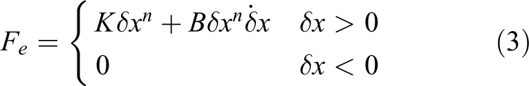
The spring model is the simplest contact force model. Though different models had shown better consistency with real environment, it is still one of the dominate approach in related research.
29,32,33
It denotes a proportion relationship between the penetration and contact force. The only parameter is the stiffness K

where δx represents the penetration depth into the environment and K denotes the environment stiffness.
Another common environment contact dynamic model for teleoperation is the Kelvin–Voigt model, which incorporates the dynamics of a linear damper-spring system

where B denotes the environment damping. While the inertia term may be included in popular second-order model, it is often neglected as the environment is usually stationary or quasi-static for most applications.
Nonlinear model has been shown to have better agreement with the real dynamic behavior of physical environment. The Hunt–Crossley model is the most popular nonlinear model for contact dynamics in teleoperation
where n is a constant typically lies between 1 and 2. The complexity and accuracy of the above-mentioned three models increases in turn and the selection of modeling approach requires a appropriate trade-off in each context.
Although the Hunt–Crossley model is nonlinear, a single-stage method is proposed to linearized it by taking the natural logarithm of both sides of the model for δx > 0. 34 Consequently, the Hunt–Crossley model can be identified using common methods. But even so, the Hunt–Crossley model is still have difficulties for practical application. The applicability of estimation method is limited as its validity and consistency requirement, for example, low damped environment and low operation speed. More importantly, experiments in the studies by Haddadi and Hashtrudi-Zaad 24 and Achhammer et al. 35 show much slower converge speed comparing to Kelvin–Voigt model, which probably caused by additional exponential parameter n.
For the Kelvin–Voigt model, experiment results in the studies by Achhammer et al. 35 and Yamamoto et al. 36 show that the B hardly converges and it may fluctuate significantly while the K has good convergence. While the Kelvin–Voigt model obtains slight smaller force error at the cost of complicity comparing to spring model, the identified damping character is useless for most controllers. Moreover, as slight difference in haptic feedback signals is not perceivable for human operator, it is hard for the operator to find this minor improvement. The threshold of human perceptual discrimination for haptic signals is referred to as just noticeable difference (JND). As reported in the study by Hirche and Buss 37 , the JND of force is approximately 10%. In contrast, the various adaptive robot controllers of usually accords with the environment stiffness and have acceptable accuracy. The simplicity of spring model also facilitates the estimation process and makes it a more practical choice. This partly explains the popularity of simple spring model that is also used in our experiments.
Model identification
A number of model identification method were investigated for estimating the model parameters.
23,38
The self-disturbing recursive least squares (SPRLS) is a common method used in recent studies as it can be immune to noise and track variable environment at the same time.
23,24,35
The update equations of SPRLS can be written as follows
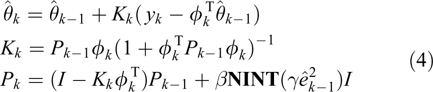
where Pk
is the covariance matrix at time instant; k,

When the error is lower than the maximum error bound determined by γ, the self-disturbing term is equal to zero and it is identical to the regular exponentially weighted recursive least squares algorithm that have good convergence character. Otherwise the Pk is increased according to the error and the sensitivity gain β, which means the latest data are endowed with larger weight in the estimation process. Thus, the SPRLS can be immune to noise and have great ability of tracking variable parameters as well. One limitation of SPRLS is that its performance heavily depends on appropriate value of the designed parameters γ and β. Although the SPRLS had been used in many studies, guide or discussion on the selection of design parameters is missing.
In practice, prediction error is usually caused by the mismatch between the real contact dynamics and the model characteristic instead of the force measurement noise. Such a mismatch causes inevitable error between the calculated force and measured force even with the optimal parameters. γ determines a minimum error level is to be considered as signal of changed environment dynamics. Thus, the threshold determined by γ is tuned to be slight larger than the maximum error caused by the mismatch and β is tuned according to the scale of parameters in our experiment.
Environment model updating algorithm
Stable force rendering on the master side is vital for MMT. However, the model updating during the operation task may induce unstable force rendering. For example, when the salve end just made contact with a object, which is stiffer than that in local model, the stiffness in local model should be updated as soon as the real stiffness is received so that it could reflect the real environment property correctly. However, the force feedback is rendered continuous and relies on the stiffness. The update of stiffness will cause larger force increment in short time and such discontinuity of the force feedback would hazard the system stability.
Parameter-based model updating
Gradual-update scheme has been adopted in MMT. With the gradual-update strategy, the model parameters were changed in a fixed change rate or in a fixed time period in some cases. The update law for position updating can be written as below while the stiffness updating is similar

where xe
is the received environment position,

where fm
, xm
, and km
represent the force feedback, position, and stiffness on master side, respectively. The force variation induced by parameter vf
can be describe as

where
There are two passivity-based model update strategies that ensure system passivity. The one in the study by Mitra et al.
26
was a basic approach that delayed the parameter changes until the update introduces no energy increment. The newer one proposed in the study by Xu et al.
27
used an adaptive virtual damper to dissipate the energy generate of the model parameters, and thus it was more efficient than the former one. For spring model in one-degree of freedom (1-DOF), the passivity condition for separate stiffness updating and position updating was given as


where
While the passivity-based methods guarantee the system passivity, the impedance of human arm has not been considered. Human arm contributes to system stability by adjusting itself. Small energy generation is most likely to be dissipated by human arm and the whole system including the human operator is still stable. Therefore, a update strategy that strictly complies with the passivity condition is too conservative in application. However, this is still an open issue as it is so difficult to take human arm damping into design of passivity-based methods (the damping property of human arm is too complicated to be modeled). Another important defect of passivity-based methods is that it cannot deal with the condition that the system energy is decreasing. These weaknesses of gradual-update scheme and passivity-based methods motivate us to find a better approach and the proposed force-based model updating method is introduced in next section.
Force-based model updating
To the best of our knowledge, all existing approaches aiming to solve the effect of model jump, control the variation of the force feedback in an indirect way, that is, they control the change of model parameters, and thus limit the abrupt change of force. However, we do not have to control the model parameter in the transition state, as the output that user can perceived the force feedback is the force rendered by the force-feedback device. In other words, the key novel idea is that we can deal with the model jump effect by directly controlling the rendered force instead of updating the parameters step by step. In the model updating process, the goal is to make the force feedback from the master device to be identical with that obtained the computation result with latest parameters as soon as possible. The only constraint is to avoid abrupt force change and make it easy for human to handle. Both the goal and constraint are about the force rather than parameters. Thus, implementing model updating in the level of force instead of model parameters is a more reasonable solution, which can be referred as force-based scheme. By modifying the force instead of model parameters on which the force is based, we are able to avoid the detour and redundancy and the model updating could be much more efficient.
The difference of parameter-based model updating and force-based model updating is shown in Figure 2.

Parameter-based and force-based model update schemes.
For now, the challenge becomes how to develop such a model updating algorithm at the level of force rather than model parameters. An intuitional approach is to limit the change rate of the force feedback to avoid the strike of “model jump effect.” We can constrain the force change rate to a safe range with smaller value than a threshold to ensure stable interaction. However, according to our experiment, a smaller force change rate can bring significant negative effect on user’s operation while a larger force change rate does not. An intuitive example can make it more clear. It is easy for the operator to decrease the contact force toward a virtual wall from 5 N to 1 N in approximately 0.2 s with a neglectable movement. But if the user is holding still with a force at 5 N, and then let the force decreases to 1 N in 0.2 s without any warning in advance, the user’s hand will move forward suddenly with a feeling of “missed step.” Note that the force change rate in the two cases is the same. We can conclude that an appropriate force change rate depends on the specific conditions and thus is difficult to set. Instead of force change rate, we need a new criterion that helps us define a safe range for stable interaction.
Once human is involved on the master side, whenever the user executes a motion or hold still, a force is expect roughly and unconsciously due to human’s physical intuition. It is assumed that when a movement is executed, both remaining unchanged or changing according the displacement and the stiffness of the environment are acceptable and easy to handle for users. Meanwhile, the force should not be larger or smaller than these two. Such an assumption has been validated through experiments and further explanation can be found in last section. The range between these two values will be used as a safe range in the design of force-based methods.
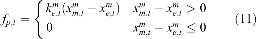
The aim of model updating is to make the force rendered by the force-feedback device fm equal to the predicted force fp , which calculated by the latest model parameters. Thus, it is preferred that fm changes in the direction that reduce the error between fm and fp , the opposite direction is undesired. Thus, a value within the aforementioned range can be set as the expected force fex . So the force fp calculated with the latest parameters transmitted from the slave side can be divided into two parts, the expected force fex and the abrupt force fab . By limiting fab , the force feedback is close to the range that is easily to be handled by operators and thus the stable interaction is ensured.
Based on the foregoing discussion, the update scheme of the force feedback fm
on master side is defined as follows. First, the predicted force fp
is calculated
Then, the maximum and minimum expected force


Then, the selected expected force is obtained as

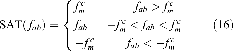
The force to be rendered by the force-feedback device can be obtained

where rendered force fab,t
= fp,t
− fex,t
and SAT() is a saturation function defined as
where
The rendered force can be divided into two parts: one is the reasonable force expected by the user fex and the other is the abnormal part. Note that in the steady state where no model updating is needed, fex is exactly equal to fp and thus we obtain fm = fp , which means the force render is accurate. In the transition state when fm is not equal to fp , the fm is close to fex . Stable interaction is ensured since fex is an expected force that can be handled effortlessly. Moreover, via the selection of fex , the fm is approaching to the fp as soon as possible. Once the fm is equal to fp , the modeling updating is finished and normal force rendering is also achieved with the given force updating scheme.
Adaptive impedance controller
Slave controller in MMT
Transition states occur irregularly during teleoperation due to inaccurate environment estimation or environment changes. In this case, the command made on master side is based on inaccurate state information, which may result in undesirable and risky deep penetration or large contact force on slave side. The main challenge of slave controller in MMT is to carry out the master command under an uncertain or unknown environment meanwhile maintains the stability of the teleoperation system.
Figure 3 shows model mismatch issue during the transition state. Both position mismatch and stiffness mismatch may cause overlarge contact force using conventional position control approach. Fortunately, the model mismatch problem is only partly solved, either by switching position/force control or by relative tracking method.

Model mismatch in MMT. MMT: model-mediated teleoperation
Switching position/force control is the most frequently used slave controller in MMT. The slave switches to force control mode when the measured contact force exceeds a preset threshold. In the force control mode, the contact force is effectively controlled and thus the overlarge force is avoided in both cases of position mismatch and stiffness mismatch. However, if the stiffness of remote environment is smaller than that of the local model, in order to apply the same contact force, the slave will penetrate to the contact object large than the master side even though the larger penetration is probably not the user’s intention, that is,. once the stiffness mismatch exist, potential overlarge penetration may occurred and damage the contact object.
Relative tracking had the same framework of PD control but modified it based on the relative positions and velocities. The original PD controller for position tracking is

where FIm
is the force applied to the slave and kps
and kds
are the PD gains. Relative tracking method modified it to

where
With such a modification, relative tracking method greatly improved the position tracking performance in the case of position mismatch. However, it cannot solve the stiffness mismatch issue. Considering the stiffness mismatch exists, for example, when the slave is to contact an object, which is stiffer than what supposed on master side. There would be no position mismatch, for example,
Adaptive impedance controller
As discussed earlier, either one of the two slave controller cannot address the potential stability issues in transition state. A possible solution suggest in the study by Xu et al. 12 is using a hybrid control scheme and the slave do not execute any motion commands whenever the contact force or the penetration has reached the values as them on the master side. However, it has not been verified that the frequently interruption and switching operation would degrade of execution efficiency significantly.
Inspired by the wide used impedance controller in compliant control and its advantages, we figure out an adaptive impedance controller for the slave control in MMT. The original idea of impedance control is to control force and position simultaneously and it indirectly controls a dynamic relationship between these two, that is, using reference inputs of both desired force and position is allowed. But the application of impedance controller usually involves only one input, while the other is neglected or adjusted adaptively. 39,40 One possible reason is using two reference input requires the command conforming to environment dynamics, which is not possible in most cases.
However, the local model in MMT enables the operator to give both force and position input at the same time. More importantly, they are reproducible on slave side and useful for slave controller to understand the operator’s intention. In the steady state, the rendered force on master side is calculated by the accurate estimating of remote environment dynamics. This means both the rendered force and its corresponding position conform to real environment and can be reproduced on slave side simultaneously. Although minor error is inevitable due to the deviation of local model, the residual error is no more than the modeling error. As far as we know, this is the first work that leverages the inherent interaction between impedance controller and MMT. In comparison with switching position/force control, our approach can realize compliant contact while avoiding the chattering problem. In addition, the adaptive impedance controller’s behavior is more similar to the human arm that is identified as an impedance module in some teleoperation frameworks. 9,41
Consider the low inertia and frictionless nature of common haptic devices on master side, for example, Geomagic Touch, together with the limited velocity and acceleration in teleoperation, the rendered force output by haptic device has very little difference with the operator applied force. Therefore, it is feasible to use the rendered force on master side as the desired force on slave side.
The overview of proposed controller is shown in Figure 4. In the proposed controller, both master position and rendered force are transmitted to slave side as the reference inputs of the slave impedance controller. The design parameters in controller are adaptively adjusted.

Structure of the controller.
For the impedance controller, the desired impedance model (in the case of 1-DOF) is specified as


where Md
, Bd
, and Kd
are the desired inertia, damping, and stiffness, respectively; ef
= fe
− fd
; and xd
is the desired position, fd
is the desired force, x and fe
are the actual position and actual force;
When the slave is moving in free space, both fe and fd are zero, and the impedance controller is equivalent to a position controller. With a fixed high desired stiffness Kf , that is, high proportional gain, accurate position tracking could be achieved.
In the case that the slave is contacting with environment, we first assumed a static environment for the simplicity. It is also not considered the direction motion tangent to the environment surface, which means no sliding. The method can be easily extended to these cases, with a modification of parameter when estimating the stiffness and penetration at the same time.
42
Let xs
and xm
denote the penetration on slave and master sides, respectively. For an environment represented by spring model, fe
can be approximate by

where Ks
denotes the stiffness of environment. With SPRLS and spring model, Ks
can be obtained shortly after the contact occurred and as the estimation of Ks
is on slave side and thus is immune to communication delay. fd
is the rendered force on master side

At the equilibrium point, we obtain

Plugging equations (21) and (22) to equation (23), we obtain

For both position mismatch and stiffness mismatch, we expect the following relative bounded of fe
and xs
for safe operation


where αF and αP are constant larger than 1, respectively, denoting the acceptable ratios of actual contact force to desired force and actual penetration to desired penetration.
For the restriction of force, using equations (21) to (23) and (25), the following condition can be obtained

Similarly, for the restriction of penetration, the following condition can be obtained
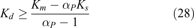
Note that ∀ Kd
> 0 meet equation (27) when Ks
< αFKm
and ∀Kd
> 0 meet equation (28) when Ks
> Km
/αP
. In addition to restriction of overlarge force and penetration, the impedance controller’s performance can be improved by adjusting the parameters based on environment stiffness.
43
To this end, defines Kd
= F(Ks
) where F(Ks
) is set toward best controller’s performance without the consideration of potential overlarge force or penetration issue. Generally, the rule of Kd
in order to meet equations (27) and (28) can be determined as following

With regard to an intuitional explanation, larger Kd can be seen as more weight on position tracking. Emphasis on position tracking is a conservative approach when the environment is softer than estimated (as an extreme case, the master is contacting while the slave is not). Similarly, smaller Kd means force tracking is preferred when the environment is stiffer than estimated (such as the slave end is contacting while the master end is not).
Once the Kd
is determined, Md
and Bd
can be selected on the basis of both Kd
and Ks
to shape the closed-loop transient behavior. The damping ratio ξd
is given by
To overcome the contact instability problem, critical damping or over-damped is preferred.
The modeling error can be denoted as em
= Kmxm
− Ksxm
. Then, eqaution (23) can be transformed as following by substituting fe
= Ksxs
and fd
= Ksxm
+ em
into it

Consequently, we obtain the only equilibrium point

Since |em | is lower bounded, it can be easily obtained that |xs − xm | is upper bounded as long as Ks + Kd is lower bounded. Kd is set to a high value when Ks is small and |em | is relatively small (usually less than 0.1fe ). It is safe to assume that the tracking error |xs − xm | is acceptable for most teleoperation tasks. It is worth noting that the fd and xd are the input of the impedance controller, the tracking ability of system does not depend on the adaptive parameter Kd . In fact, when the modeling error is neglectable, xs will converge to xd no matter how Kd changes by the estimated environment stiffness.
Note that the position tracking error are based on the equilibrium point of contact, the penetration or contact force may exceed the bounds due to abrupt change of environment, modeling error, dynamic error, and so on. However, as shown in the “Experiments” section, the overall restriction is effective.
Experiments
Comparison of model updating
Stiffness updating only
A simple experiment setup is used for comparison of model updating approach. Operator contacts with a virtual floor with Geomagic Touch as the force-feedback device on master side and only vertical motion is considered. A spring model is used as local model and thus the force feedback is computed as equation (1), while δx is derived by the endpoint position of Geomagic Touch and the position of virtual floor. The stiffness and position of virtual floor was updated regularly. The stiffness of virtual floor was set as 1100 N/m initially and switches between 100 N/m and 1100 N/m every 10 s. The operator was told to make contact with the virtual floor in a static or fluctuate manner. No model updating scheme is used to serve as a benchmark. As can be noted in Figure 5, the operator was unable to keep the handle still when the stiffness changes. The operator pushed the handle deeper accidentally (seeing position increase in the figure) when the stiffness decreases abruptly at time t = 10 s. The handle was pushed up (seeing position decrease in the figure) accidentally and had an overshoot when the force rendered on device increases suddenly at time t = 20 s. The maximum value of most force rendered is below 4 N. Even so, the abrupt change of model parameters imposed a significant negative effect to the normal operation.

Force and position without model updating.
Three model updating methods were tested in the same condition. The stiffness change rate in gradual-update scheme and
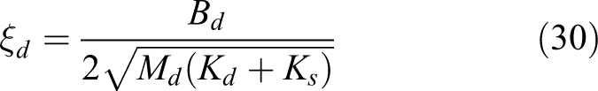
Figure 6 demonstrates the results of passivity-based method, the force changed very smooth at time t = 20 s. However, at time t = 10 s, the force diminished suddenly and caused the operator push down the handle in about 0.1 s accidentally because the decreased stiffness lead to decreased energy and the algorithm does nothing through the variation. This indicates that passivity-based methods should be used combining with other methods to deal with the system energy decrease. Figure 7 shows the change of stiffness during the operation. The stiffness changes from 1100 N/m to 100 N/m at time t = 10 s directly and varies from 100 N/m to 1100 N/m adaptively according to the state of the contact. When the penetration decreases to smaller value after time t = 25 s, the bigger stiffness changes rate is allowed and the update process still takes more than 6 s. The result of gradual-update scheme is shown in Figure 8, the force fm changed smooth at time t = 10 s and t = 20 s. The master handle is pushed down gently at time t = 10 s due to the decrease of force and then be handled quickly as the operator noticed the decrease of force. No position overshoot happened when increased force increase at time t = 20 s.

Force and position with passivity-based model updating.
Stiffness change in passivity-based model updating.

Force and position with gradual-update scheme.
The result of force-based updating is shown in Figure 9, which is similar to gradual-update method and the position fluctuation is even smaller. The negative effect of model jump is effectively avoided.

Force and position with force-based model updating.
Both position and stiffness updating
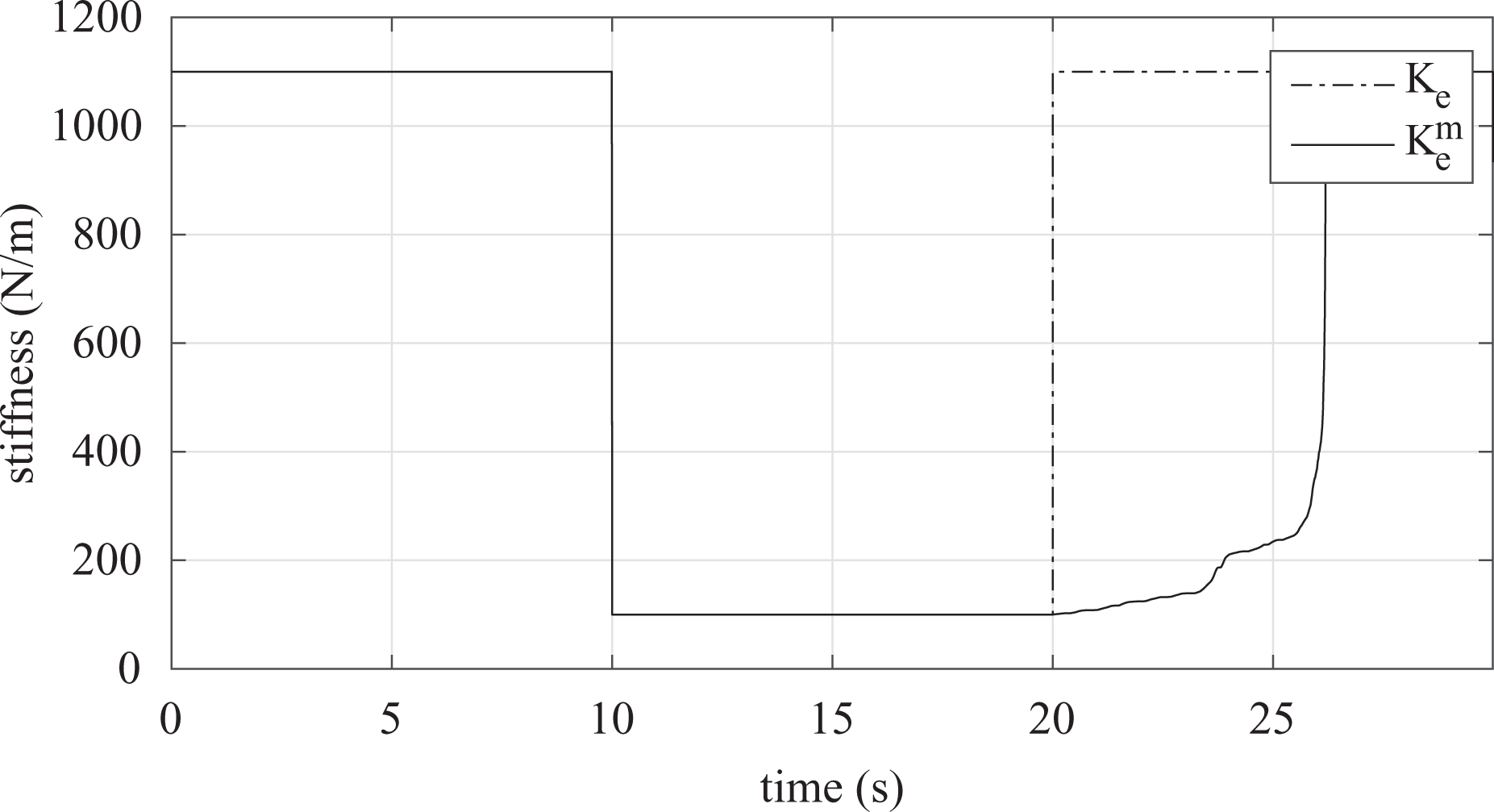
To evaluate the force-based method thoroughly, another experiment with simultaneous position and stiffness updating is conducted. Passivity-based method is not compared as no existed solution with both location and position updating there is. The stiffness switches between 1100 N/m and 100 N/m every 10 s, the position of virtual floor switches between 0 mm and 20 mm every 5 s. The initial value for stiffness and position is 1100 N/m and 20 mm, respectively. The force and position profiles are shown in Figures 10 and 11. As can be noted in the enlarged view, after the parameter updating at time t = 5 s, fm changed toward to fp directly in force-based method, while it fluctuated in graduate-update method. Note that in the transition state started from t = 5 s, fp is always bigger than fm which means the fluctuation of fm is unnecessary and inefficient. This is also how the force-based method be more efficient than the parameter-based methods. As a result, the force-based method takes only 2.52 s for model updating while the gradual-update scheme takes 5 s.
Force and position with gradual-update scheme, while both location and stiffness are updated.
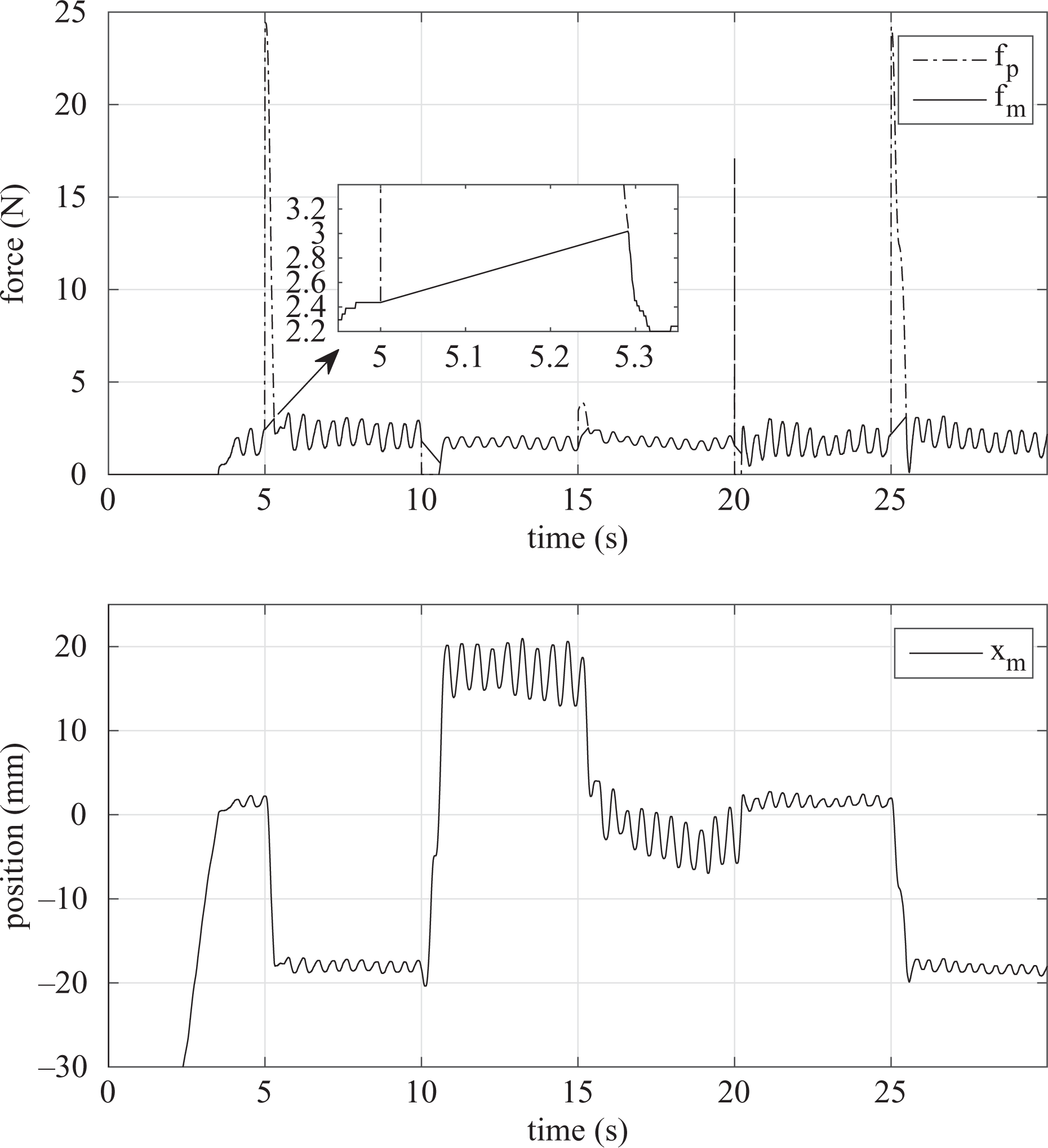
Force and position with force-based model updating, while both location and stiffness are updated.
The abrupt force during the operation of two methods is compared and shown in Figures 12 and 13. The maximum and average values of fab for gradual-updating scheme are 0.062 N and 0.009 N, respectively. In contrast, the maximum and average values of fab for force-based methods are both only 0.002 N. Smaller fab indicates that force-based method may provides more comfortable interaction.

Abrupt force profile with gradual-update scheme.

Abrupt force profile with force-based model updating.
The results of gradual-update scheme and force-based approach are summarized in Table 1. It shows clearly that the proposed approach provides a much better model updating performance with high efficiency and smooth user experience.
Comparison of model updating algorithms.

Comparison of slave controller
Setups
To evaluate the proposed controller, we used a MMT system as shown in Figure 14 with a Geomagic Touch as the master haptic device and a 3-DOF translation parallel manipulator as the slave. An ATI mini 40 force sensor (ATI Industrial Automation, Inc., NC, USA) was mounted at the end-effector of the slave robot to measure the contact force. Currently, for simple, only 1-DOF motion in vertical direction was allowed.
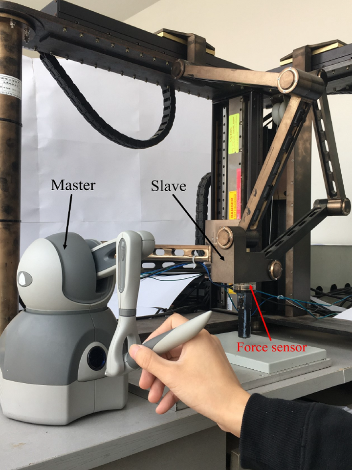
Setup of the teleoperation system.
For online parameter estimation, spring model was used as the local model and SPRLS is utilized. The online estimation process was implemented at the slave side by the force sensor data. Specifically, the estimation result is updated by equations (4) and (5) at position measurement frequency 170 Hz. The threshold for detection of contact was set as 0.05 N. The place where a contact happened was considered as the position of environment, therefore δx can be easily obtained. The estimated environment stiffness and position were sent back to the master side and the force feedback is computed using equation. (1). It should be noted that the environment position and stiffness used for force computation came from the slave side under time delay. When accurate position and stiffness is obtained, a non-delayed accurate force feedback will be provided to users. One practical trick used is that, when the slave reaches the environment according to the environment and no contact is detected, the slaves current position is sent back to replace the location of environment. In this way, the known information that the environment location is lower than the current location is utilized, and the modeling error is minimized.
For the proposed controller, position-based impedance control is used to carry out the command of impedance model. Md
is set to 2 Kg and Bd
is set according to equation (30), while ξd
is set to 1 for better transient behavior. F(Ks
) is defined as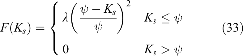
where ψ and λ are constant setting before the operation tasks. Specifically, ψ, λ, and Kf were set to 8000, 5000, and 5000 N/m, respectively. Both αP and αF set to 1.3, which means 30% larger force and penetration are expected. The other parameter settings are invariant for all the following experiments except the time delay. To validate the robustness of the proposed approach, a delay of 2 s was given in the comparison experiments and 5 s time delay was used in the continuous contact experiments.
As shown in Figure 15, different contact materials (environments) were used for the experiment. They included a rubber pad, a foam, and a metal cover board. The stiffnesses of the three materials are approximately 400, 6000, and 19 000 N/m, respectively.
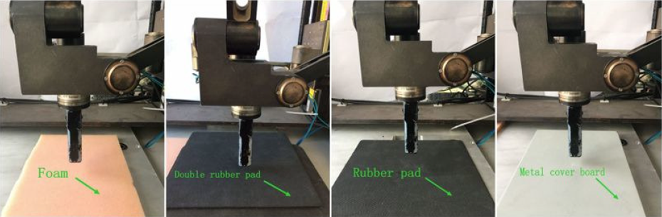
Contact materials in experiments.
The proposed controller was first validated in comparison with the switching position/force control method 12 and the relative tracking method. 19 Then, it was evaluated in a continuous contact experiment with changing environment (both stiffness error and position error exist). For the convenience of observation, all curves plotted in the figure are translated by 2 s along the time axis to counteract the forward time delay.
Potential of existing approaches
The experiments were designed for detecting the potential of existing control approaches. Both forward and backward communication time delay were set to be 2 s and the feedback from the slave side was blocked to maintain a transition state. The initial stiffness in local model was set as 2000 N/m in every trial. Comparing with the environment model on master side, foam is a lower stiffness environment, while rubber pad and metal cover board have higher stiffness.
In the first set of experiments, the slave was in contact with a rubber pad using relative tracking, which is a harder environment than expected. As shown in Figure 16, while the position tracking is accurate, the slave contact force is much larger than master due to unexpected larger stiffness. The overlarge force is unpredictable for operator and may damage the remote environment and the stability of the system. The results using the proposed controller in the same condition are shown in Figure 17. It is verified that the controller effectively restricted the unexpected over large force when it encountered an unexpected high environment stiffness.

Force and position with relative tracking (hard environment).

Force and position with adaptive impedance controller (hard environment).
Another experiment is to contact with foam, which is a softer environment than expected, using switching position/force controller. The results are shown in Figure 18. The force controller drives the slave to a position higher than master obviously which will cause large and dangerous penetration in order to obtain desired contact force. In contrast, as shown in Figure 19, the overlarge penetration may be avoided using our impedance controller. The comparison results are summarized in Table 2. As could be expected, during the transition state when the local model on master side exists error relative to the real environment on slave side, the proposed impedance controller can ensure task be carrying out by a conservative way. The slave contact force and penetration were restricted to a safe range when the stiffness does not match, which is impossible for other approaches.

Force and position with switching position/force controller (soft environment).

Force and position with an adaptive impedance controller (soft environment).
Comparison of slave controller.

Continuous contact experiment
To validate the proposed controller thoroughly, we conducted the experiments on changing environment in which both position and stiffness of the object are varying and unknown by the operator in advance. The initial stiffness in local model is still 2000 N/m. Different from former experiment sets, the master received the estimated parameters from slave side and updated the local model for accurate approximation. Thus, the operation will entry to the steady state from transition state during the operation. To mediate the model jump effect while updating parameters, the force-based model updating is utilized and the
The operator was allowed to contact with different environment. The order of contact material is rubber pad, foam, double rubber pads, and metal cover board. The full process of the experiment can be seen in the Online Supplementary Video. The result of online parameter estimation is shown in Figure 20. The initial stiffness value was 2000 N/m and converges to corresponding value once the slave is in contacting with a new environment. Four steady stages at 7000, 400, 5000, and 19,000 N/m represent four different material stiffness, respectively. The converge of stiffness estimating takes only a few seconds and no undesired overshoot happened. Besides, the estimation algorithm can distinguish the difference between the rubber pad and double rubber pad apparently, which further suggests the accuracy of the parameter estimation algorithm. Overall, the online stiffness estimation employed in the system worked effectively. On the other hand, the quick variation of stiffness at such a magnitude challenges the model updating on the master side. It will be shown soon that the proposed model updating algorithm’s performance is satisfactory as expected.

Result of online parameter estimation.
The position tracking and force-feedback results are shown in Figure 21 and the enlarged views of four stages are shown in Figures 22 to 25.

Continuous experiment of adaptive controller.

Continuous experiment of adaptive controller: contact stage with rubber pad.

Continuous experiment of adaptive controller: contact stage with foam.

Continuous experiment of adaptive controller: contact stage with double rubber pads.

Continuous experiment of adaptive controller: contact stage with metal cover board.
Since position and stiffness of all four different environments are unknown to user, there are position error and stiffness error at the initial phase of the each contact. As a result, both accurate position tracking and force feedback may not be achievable and proper action must be done to avoid overlarge force or penetration. For example, as shown in Figure 22, the slave tracking the master before time t = 8 s. Because the position of environment model on master side is lower than the real one, the master kept moving downward without force feedback. While the slave was in contact with the environment but the master did not, the impedance parameters of the controller were adjusted in order to avoid overlarge contact force so the slave did not go on tracking the master. Meanwhile, the new environment position was transmitted back to the master. After the command based on corrected environment model is sent to the slave, both position tracking on slave side and force prediction on master side are achieved. The impedance control scheme adopted in the controller provides a high degree of robustness to robot unmodeled dynamics and the unknown environments. As a result, which also demonstrated in the plots, the controller not only effectively avoided overlarge contact force and penetration but also guaranteed the smooth trajectories.
It is worth noting that the master position changed smoothly when the model parameter abruptly at time t = 10, 55, 112, and 175 s. The operator also can feel smooth force changing during the whole experiments, which validated the effectiveness of the model updating strategy.
As shown in Figure 25, when the position of local model on master side is higher than the real one, the operator feels like the slave is in contact but it is actually not, then the controller will drive the slave to slightly surpass the position of master. It can help the slave “found” that the real environment position is farther than expected. As a result, the slave is able to keep moving until it makes contact with the environment and the environment position in local model becomes correct.
The point is that both overlarge force and penetration are effectively avoided under unknown environment and large time delay, which is impossible for conventional bilateral teleoperation approaches. The residual tracking error comes from the dynamic error and modeling error. The tracking error, when contacting with metal cover board, is minimum in the four cases due to high stiffness and small modeling error.
Discussion and conclusions
In this section, we offer some discussion about the proposed methods and position-dependent environment dynamics model, which is necessary for the application of MMT at a higher level.
Discussion on proposed methods
For the force-based model updating algorithm, it is believed to be more effective than existing parameter-based approaches. Actually, the goal of the parameter updating in MMT is to maintain the stable human–machine interaction and make the rendered force equal to the force calculated via latest model parameters as soon as possible rather than update the model parameters step by step. While updating the parameters step by step is surely feasible and useful, which also have been used wildly, the force-based method can make full use of the feasible space to accomplish its task. Thus, model force updating is a more reasonable and more effective solution in comparison with the parameter-based methods. Note that the same allowed abrupt force
For the slave controller, the primary limitation is that either position or force cannot be controlled precisely. It is also worth to point out that, for the proposed approach, obtaining ideal tracking in steady state requires environment can be represented by spring model. As shown in Figures 22 and 25, the strong nonlinear dynamics of foam lead to apparent larger tracking error. Modification toward nonlinear contact model needs to be investigated, thought it may lead to a complicated boundary condition. Besides, as can be noticed in Figure 22, the slave position tends to be lower than the master side. The reason of this trend possibly is that the slave is designed to be controlled by a position controller based on a simple PID controller without gravity compensation.
Another possible concern is the stiffness of the robot. It is well-known that stiffness is important to any robotic system’s performance. 44 In a MMT system with the proposed controller, the geometry change of the robot means that the estimated environment stiffness is coupled with the stiffness of the environment and slave manipulator, so the modeling accuracy may degrades. In addition, the stiffness of end-effector force sensors also contributes to the error. Fortunately, even though the stiffness properties of the slave manipulator cannot be neglected. We can easily found that since the environment is modeled to include the stiffness of both environment and slave manipulator, the force tracking does not degrade like the position tracking, which is comforting for most force-feedback teleoperation tasks.
The stiffness analysis of a robotic system is a general issue in robot control rather than a teleopration problem. However, a complete analysis that takes the slave manipulator’s stiffness performance into consideration should be done in future work due to their importance for a successful robotic systems.
Position-dependent environment dynamics model
Different from typical simplified task in the experiment that has only one contact point, in real complex tasks, environment model must be position-dependent so as to match the position-dependent nature of environment impedance. Position-dependent model was proposed and has shown its advantages comparing with time-based approach. 28 The workspace is quantized into discrete components and each of them represents a small area in the slave robot’s workspace. The estimated parameters are stored in the data node corresponding to the current tip position of the robot. Thus, prestored estimated parameters can provide prior knowledge when the robot back to the same position to shorten transition state.
However, it is still an open issue. In current position-dependent model, only parameters in measured position are updated while others remain the initial value. Considering the large amount of data nodes, only a few part of information in the model can be updated using the direct measurement. The model works only when the new contact point is the exactly one of the previous contact points. While the operator on the master side may be able to estimate the impedance in an unmeasured position empirically and manual adjustment by operator leads to significant decrease in operation efficiency. Meanwhile, making use of more available information to estimate the parameters before the real contact happened plays an important role as it determines the difference between local model and remote environment at current position. If the estimation is accurate, there will be no transition state in current contact point. In addition, unnecessary dramatic changes between updated points and the others will be introduced if the estimated parameters differ greatly from the initial value.
To solve this problem, a mechanism to estimate the environment model parameters in unmeasured position is needed. Meanwhile, its computation complexity must be limited so that it can keep compatible with high refresh rate.
Considering the physical characteristic of common environment surface, the parameters are continuous in most areas even in the presence of dramatic changes at the boundaries, which can be either visible or invisible. The environment impedance in one position is usually similar or even identical to the impedance in near position when the material in these positions is same. In addition, teleoperation system usually has a camera and the vision information is valuable for estimating parameters of contact dynamics model because the images show which part surface of environment are in the same appearances. Same appearances mean possible same material and thus similar dynamic characteristic. The perceivable boundary may mean different object or material surface, which has different or unrelated impedance characteristics. Note that estimating environment impedance by vision and measured sample is in accord with human common sense. It is reasonable to assume that the near area has the similar impedance.
In order to estimating environment parameters before contact, we propose a method that consists by two steps. First, get the image of the environment surface and extract the contour. Then divides the position-dependent model into many regions using the extracted contour. For the accuracy, the division can be done by operator manually. The expense on this process is acceptable because it is only a one-time effort. Second, every time a new estimated result is given, updating the data node corresponding to the current position. Then using nearest neighbor interpolation to obtain the value of all unmeasured data nodes.
Although the interpolation does not guarantee the accuracy as there is no any direct information, it is difficult to prove its effectiveness theoretically as we cannot obtain mathematical formulation of the unknown real environment. It is believed that this method is effective in most cases based on the discussion before. An improved estimation of environment impedance not only shortens the transition state but also accelerates the parameter estimation process and thus improves the impedance controller’s performance. 28 In addition, the improved model can be used to display a continuous impedance map of the environment to give the operator a visible description of environment dynamics. This is particular valuable for palpation or damage detection tasks. A similar application was investigated in the study by Yamamoto et al. 22
Conclusions
As an alternative to bilateral force-feedback teleoperation, MMT is developed to enable efficient operation especially under large time delay. In this article, we put forward a force-based model updating algorithm and an adaptive impedance controller to improve the stability of MMT.
We firstly proposed a new force-based approach to solve the model jump effect in MMT. The force calculated by the latest model parameters is set as the target, and it makes the rendered force to approach the target as soon as possible. By dividing the rendered force into normal part and abnormal part, then the abnormal part is limited to ensure stable interaction and the normal part is retained to respond the normal operation. By accomplishing the model updating more effectively, the force-based methods are able to significantly improve the updating efficiency compared to the existing solutions while ensuring a stable human-machine interaction.
On the slave side, motivated by the potential risk of current slave controllers, an adaptive impedance controller was introduced. We leveraged the specialty of MMT that both force and position can be acquired for slave controller, which give two reference input to the controller. Meanwhile, by comparing the real environment stiffness with the one in the prediction model on the master side, the impedance parameters were adjusted automatically. As a result shown in both theory and experiment, when there are errors between the prediction model and real environment, the slave executes the task in a conservative way that emphasis on force or position accordingly to avoid undesired large penetration or contact force. Together with the switching-free characteristic, the proposed controller is deemed to provide better stability and safety for MMT. We implemented the controllers in a 1-DOF experiment system. Experiments results on different environment material verified the superiority of the proposed methods.
Although the results in the experiment is encouraging, it is worth noting that obtaining ideal tracking and force feedback under large time delay requires more accurate environment model. In addition to the environment dynamics model, the geometry model of environment is also needed and vital for the application of MMT.
Future work consists in the extension of proposed controller to a multiple degree of freedom tasks and the experiments with improved position-dependent environment model. Furthermore, a comprehensive and theoretical stability analysis is needed.
Supplemental Material
Supplemental Material, Demonstration_Video - Model-mediated teleoperation with improved stability
Supplemental Material, Demonstration_Video for Model-mediated teleoperation with improved stability by Jingzhou Song, Yukun Ding, Zhihao Shang and Ji Liang in International Journal of Advanced Robotic Systems
Footnotes
Declaration of conflicting interests
The author(s) declared no potential conflicts of interest with respect to the research, authorship, and/or publication of this article.
Funding
The author(s) disclosed receipt of the following financial support for the research, authorship, and/or publication of this article: The project was supported by the Open Research Fund of Key Laboratory of Space Utilization, Chinese Academy of Science (no. LSU-2016-05-2).
Supplemental material
Supplementary material for this article is available online.
References
Supplementary Material
Please find the following supplemental material available below.
For Open Access articles published under a Creative Commons License, all supplemental material carries the same license as the article it is associated with.
For non-Open Access articles published, all supplemental material carries a non-exclusive license, and permission requests for re-use of supplemental material or any part of supplemental material shall be sent directly to the copyright owner as specified in the copyright notice associated with the article.