
Abstract
This article shows the characteristics of a sprawling robotic leg inspired by the limb postures of certain reptilian animals known as sprawling-legged creatures. The main part of the robotic limb is based on the eight-bar Peaucellier–Lipkin linkage, and its main attribute is the ability to trace a true straight line, due to the rotational motion of the input link. However, when the eight-bar linkage is modified, it is capable of tracing true circular concave or convex arcs, when two of its constitutive links have distinct and precise lengths. This gives rise to the concepts of concavity and convexity, related to a robotic leg based on the Peaucellier–Lipkin mechanism, such as the one described herein. Our bioinspired robotic leg can trace concave or convex curves, as well as straight lines, making it a reptile-like robotic limb that is very similar to the natural one. We also introduce the concept of rotation center tuning, which refers to the ability of the leg to adapt its posture to the center of rotation of the entire walking machine, resulting in an easy and suitable gait process. The theoretical information is illustrated through the simulation of an example that provides a path-planning procedure, focusing on the rotation center tuning process and a walking gait. The example also includes the design of an elliptical path projected onto the cylindrical workspace and followed by the reptilian foot.
Introduction
Nature is a master source of inspiration for engineers seeking solutions to locomotion problems resulting from complex environmental conditions. Amazing quantities of animal morphologies offer successful locomotion by creeping, walking, running, jumping, climbing, crawling or even flying, or swimming. Around the world, the field of biorobotics has designed and created robots resembling their natural counterparts by mimicking their locomotions. Nowadays, there are fish-like robots as the one with four-degrees-of-freedoms (4-DOFs) called UC-Ika 1, whose swimming motion is inspired by the tuna fish 1 ; there are snake-like robots as those described by Hirose and Yamada. 2 One of the most representative cat-like robots is the Cheetah-cub, a quadruped compliant robot. 3 Igarashi and Mikami describe the development of a frog-like robot that is able to avoid obstacles by jumping and walking on rough terrains. 4 Many groups worldwide work on bipedal locomotion; there are several good examples concerning two-legged robots, one of them is Asimo, created by Honda. 5
As we see, there is a big universe of robots, many of them conceived from their natural models, presenting different strategies of locomotion, and one group of this universe implies the legged machines.
Particularly, this article focuses on the most important part of a legged system, the leg, but the limb we present is a sprawling robotic one, resembling the lizard leg. Although its conception was inspired by sprawling-type reptilian creatures, it is not a traditional zoomorphic leg. It may be surprising that the robotic leg under consideration is bioinspired from crocodilian legs but not arranged in the traditional zoomorphic way. We did not design a serial linkage system composed of a femur and a tibia connected by revolute joints, whose ends are attached to the main frame of the robotic walking machine and to the end effector or foot. Our crocodilian robotic limb contains a parallel mechanism capable of describing defined paths, on the horizontal plane, that are combinations of straight lines or true circular arcs and a sole prismatic joint that is not encountered in reptilian animals. The basis of our inspiration lies in the mechanical sprawl posture of crocodilian animals rather than their precise anatomy. In accordance with this conceptual idea, we have synthesized a mechanical system capable of positioning the robotic foot in the three-dimensional (3-D) space. It is composed of a 5-DOF mechanism, obtained from the mechanical linkage known as Peaucellier–Lipkin (PL), which is a 1-DOF system.
In summary, this article describes the criteria through which a reptile-like robotic leg was conceived. The leg is intended to be used as a locomotion unit in stable walking machines, given that the use of sprawling robotic limbs offers lower centers of mass and wider stability polygons, providing the legged machine with better stability margins during a walking gait. We decided to imitate elements of nature, because of the advantages offered by this type of mechanical architecture. Its main contribution is the use of a planar mechanism, whose central attribute is to trace defined paths, as true straight lines or circular curves, in terms of a rotary motion exerted on the input link. We present the process through which this mechanism was transformed into a new one, characterized by enhanced mobility. At the end, we present a simulation about a path-planning task to show its kinematic skills.
The main contents of this article include the following sections. After the “Introduction” section, we present the “Fundamentals and related work” section, which shows the classification of walking machines, taking into account the mechanical posture of their legs. In addition, some examples of the use of the PL mechanism are offered, as well as several mechanical architectures commonly used in the design and construction of robotic legs. “The bioinspiration model” section presents an outlook concerning the characteristics of the legs of reptilian animals. After that, the “The bioinspired robotic leg” section presents a detailed description of the principles on which the conception of the robotic leg is based, as well as the addition of extra DOFs that allow the desired mobility for this mechanism to be considered as a robotic leg. This section is very important because it explains the rotation center tuning (RCT) process, which involves a transformation of the leg prior the gait. The “Kinematics” section offers the mathematical frame through which the joint space is obtained in terms of the task space, and whose equations are used in the “Simulation” section, which is presented after the part titled as “Path-planning procedure” that summarizes the steps of the operational process. Finally, we present the “Discussion” and “Conclusions” sections, where we show the main results, advantages, and disadvantages.
Fundamentals and related work
Some authors group legged robots into mammal-type and sprawling-type 6 according to the classification of limb postures of vertebrates. 7,8 The first group refers to those machines (or vertebrates) whose legs are erect, held underneath the main frame and confined to parasagittal plane movements. 7 They are bioinspired from dogs, cats, and similar animals, whose body weights are situated directly over the legs, providing greater speed and agility. The second group includes walking robots, whose locomotion units or legs are held in a more abducted position. Their bioinspiration models are turtles, salamanders, monitor lizards, or other crocodilian animals, in which the femur is nearly parallel to the ground and moves almost completely on the horizontal plane, 7,8 with the tibia nearly vertical in some postures during the walking gait, incorporating considerable axial rotation.
Several research works have been carried out in order to determine the characteristics of the walking of sprawling creatures. As an example, Karakasiliotis et al. 9 analyze the locomotion of a quadruped sprawling animal (gecko) trotting on a horizontal surface using an intra-limb motion; they generate a simulation of the feet trajectories. These studies have permitted the creation of several sprawling walking robots. A very good example of sprawling walking machine is the biologically inspired robot Pleurobot, a salamander-like robot that closely mimics its biological counterpart, Pleurodeles waltl. It is a quadruped machine whose legs have 4-DOFs. 10,11
The sprawling limb posture is considered the ancestral condition of terrestrial vertebrates. 7,12 It depends on the sprawl angle σ of the femoral bone, which is measured from the vertical line (Figure 1). In this manner, an absolute erect leg is defined by a null sprawl angle (Figure 2(a)), whereas an absolute sprawling leg corresponds to orthogonal postures of the femur (Figure 2(b)).

Sprawl angle σ in walking machines.

(a) Absolute erect walking robot (σ = 0°) and (b) absolute sprawling walking robot (σ = 90°).
In this article, we propose an absolute sprawling robotic leg, providing a lizard-type locomotion unit. In other words, the proximal part of the robotic leg always remains horizontal and moves exclusively on the horizontal plane. This locomotion unit possesses 5-DOF and is based on the well-known 1-DOF PL linkage, which is a planar eight-bar mechanism. This bioinspired leg can be divided into two parts: the first one corresponds to the proximal part of the limb, which is based on the PL linkage. This eight-bar linkage has been transformed with the addition of three more DOFs. The second one is a single link driven by a prismatic actuator, which helps to raise or lower the robotic foot, during the sprawling step cycle or gait. Because the PL linkages are considered planar mechanisms, this robotic limb helps the whole machine to walk around a rotation axis, which is orthogonal to the plane of the PL mechanism and passes through an instantaneous center of rotation. First, the centers of rotation of the leg and the entire walking machine must coincide by means of a previous arrangement, obtained through a precise ratio between the lengths of two constitutive links. We show the procedure in which this sprawling leg adapts its posture to a specific trajectory required by the conditions of the terrain.
The contribution of this work results from the fact that there is almost no information in the scientific and technical literature on apparatuses equipped with legs based on the PL mechanism. Most walking machines use devices designed from traditional mechanical architectures composed of structures that are links coupled by either revolute or prismatic joints, forming serial or parallel kinematic chains.
The PL linkage has had several applications such as a linear haptic device, 13 a positioning device in teleoperated needle steering systems, 14 and an actuation mechanism of deployable structures, 15 among others. Its use as a robotic leg seems to be almost nonexistent, with other mechanical structures being more popular. The pantograph mechanism is widely used as a robotic leg. An example is presented by Li and Ceccarelli, 16 the Laboratory of robotics and mechatronics (LARM) leg employs a Chebyshev four-bar linkage and a pantograph mechanism. The quadruped robot, presented by Spröwitz et al., 3 uses a leg configuration, which is based on a spring-loaded, pantograph mechanism with several segments. A pantograph-jack structure as leg is described by Ishihara and Kuroi. 17
Another mechanical architecture used as a robotic leg is the parallel mechanism as the one presented by Russo et al. 18 who propose the 3-Universal Joint-Prismatic Joint-Revolute Joint (3-UPR) morphology as the basis of a novel robotic leg. They affirm that this kind of legs has good performance in terms of task and payload, nevertheless they have smaller workspaces than serial ones of the same size.
A recent category of walking machines considers the “transformable leg-wheel hybrid” robot, whose leg and wheel morphologies can be transformed through mechanical actuation. A representative example of this kind of robots is the TurboQuad. 19 Its locomotion units are transformed from leg to wheel modes depending on the conditions of the terrain, improving robots’ adaption to the environment.
Knoop et al. 20 present variable amplitude module orthogonal slider, a novel two-motor hexapedal robot that is able to walk and turn with arbitrary curvature. Its legs are based on hypocycloid mechanisms.
The bioinspiration model
Figure 3 shows a sketch of a Komodo dragon, a massive lizard belonging to the species Varanus komodoensis, whose right forelimb clearly presents a sprawling posture, which is an important attribute when dealing with the biomechanics of certain reptilian animals.

A reptilian sprawling legged animal is the inspiring model.
It is true that the limbs of this kind of animals are not absolute sprawling legs; the femur (humerus) is not always horizontal and the tibia and fibula (ulna) go from inclined to vertical postures during gait. However, for this article, for the purpose of simplifying the complexity of the real movement of a living lizard, we consider natural limbs nearly absolute sprawling legs. This way of walking has inspired the creation of a robotic leg, as the one shown in Figure 4, 21 which is an idealization of the natural model, because its proximal linkage always remains horizontal and the distal one is always vertical.
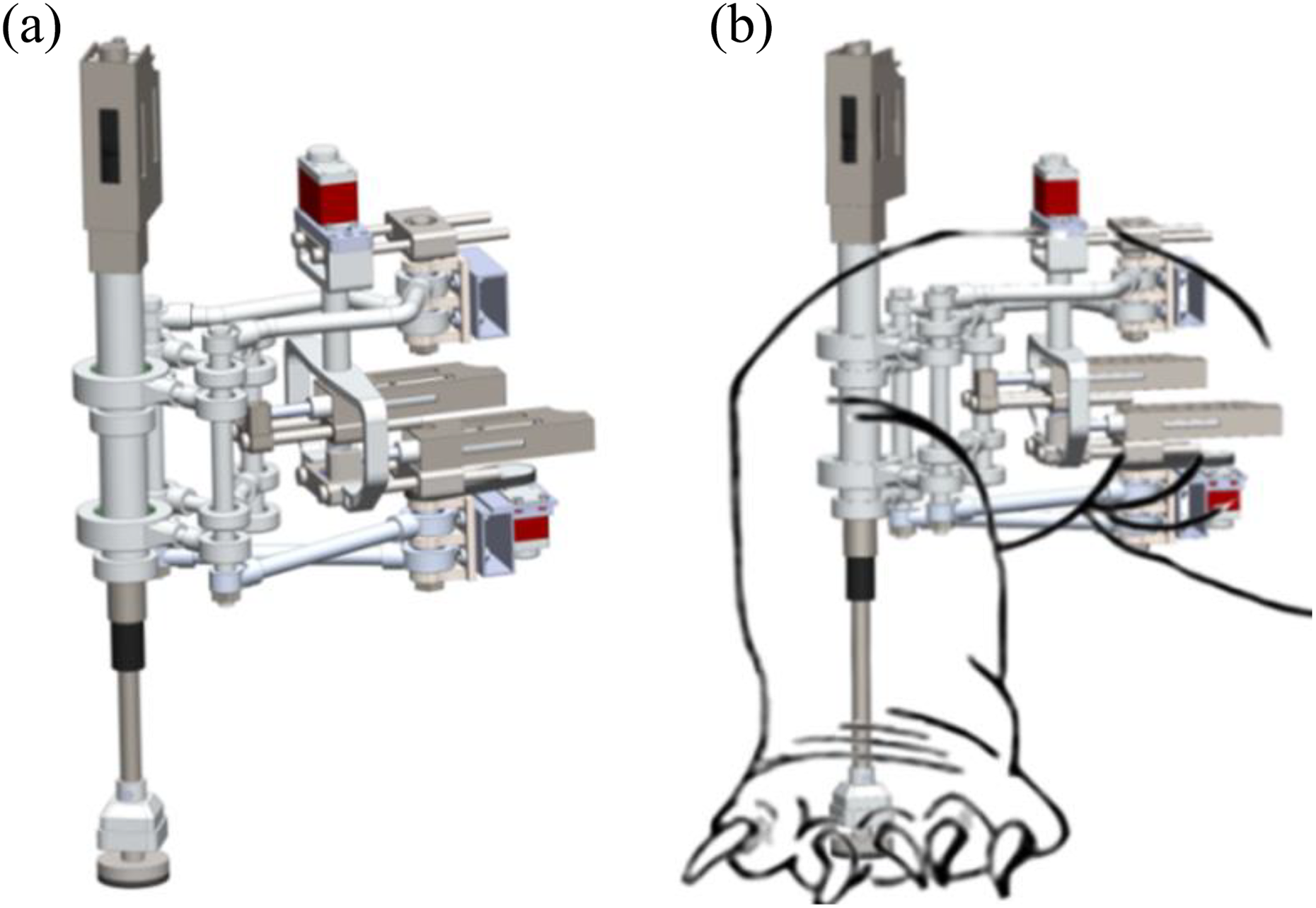
(a) The bioinspired sprawling robotic leg and (b) the natural and robotic legs are superposed.
In Figure 4(b), the robotic leg has been superposed on the natural one, in which a strong mechanical structure based on the PL linkage represents the femur or humerus, whereas the tibia or ulna is a simple link driven by a prismatic actuator. We have placed a robotic foot at the end of this prismatic link, representing the reptilian foot.
The sprawling posture of the natural animal is affected by large joint moments or muscle forces, which is why the legs of sprawling-limbed creatures are relatively short and heavily built and characterized by massive limb girdles that indicate a lumbering gait. 22 The strong robotic structure shown in Figure 4 represents the proximal linkage of such a natural leg.
There are certain reasons for mimicking a natural sprawling leg. Due to the lower height of their centers of mass and their long and wide polygons of stability, sprawling-legged animals present more stable postures (Figure 2). 23 –25 Nevertheless, walking is slower with a sprawling leg. 26 Figure 5 presents a view of the proposed legged robot with four sprawling legs based on the PL linkage as the one presented in Figure 4.

View of a sprawling-legged robot.
The bioinspired robotic leg
The proximal part of the sprawling robotic leg presented in this article, is based on the planar 1-DOF PL mechanism, illustrated in Figure 6. It is composed of eight binary links, connected by six revolute joints. Because it uses a rotation of the input link

A simplified sketch of the PL mechanism. PL: Peaucellier–Lipkin.
Description of the sprawling robotic leg
Figure 7 presents a top view of a simplified sketch of the PL-based leg. Six solid lines and two dashed segments are all connected by six revolute joints, denoted as points A, B, C, D, E, and F, and their joint axes are orthogonal to the plane formed by those six points. The lines connecting those points are denoted as

Top view of a simplified sketch of the PL-based leg. PL: Peaucellier–Lipkin
There are two sets of solid lines
Lengths of solid lines.
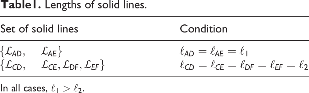
In all cases,
At this moment, the mechanism has 3-DOFs, which are capable of transforming the entire linkage: dAB, dAB, and θB. The main behavior of the PL-based leg depends on those DOFs in the following three cases: in case 1,
The PL-based leg is prepared to execute a specific path by means of dAB and dBC. Once the leg is prepared, the execution of gait takes place when θB varies. Although dAB and dBC are independent parameters, this article considers the relations given in (1) and (2), where kAC is a known constant

According to (1) and (2), dAB and dBC can be expressed as functions of rc and kAC as shown in (3) and (4).

Figure 8 shows three different postures of the same PL-based leg, where cases 1, 2, and 3 are represented by (1) when rc = 1, rc < 1 and rc > 1, respectively, for a particular kAC.

A PL-based leg presented in three different postures and paths followed by point F. PL: Peaucellier–Lipkin.
We shall now discuss a varying rc for case 2 and a given kAC. Figure 9 shows several paths followed by point F when rc decreases. This means that the coordinates of the center of rotation are closer to the coordinates of point A, moving from the left as rc decreases. At the same time, point B moves from the right toward point A. In conclusion, point A tends to be the center of rotation, whereas rc approaches zero. In case 2, point A always remains within a circle passing through the path followed by point F, when θB evolves. These facts give rise to the concept of concavit

Concave arcs drawn by point F when rc decreases in the interval
In case 3, the behavior of rc is different from its behavior in case 2. Figure 10 shows case 3 when point B moves away from point A, moving to the right, from the midpoint between A and C, when

Convex arcs drawn by point F when
In the present article, the meaning of concave and convex paths makes sense when an observer is placed at point A.
Degrees of freedom and their use
The reptilian robotic leg is a positioning device capable of placing its foot at a point in a 3-D space. The basic PL linkage possesses 1-DOF through which it is capable of tracing straight lines, as shown in Figure 6. However, we show that the PL mechanism is able to describe concave or convex circular arcs when rc ≠ 1. This is possible when dAB and dBC change their values according to the rules given by (1) and (2). As a consequence, the basic PL mechanism must be transformed with the inclusion of two more DOFs. Both of them use prismatic joints driven by linear actuators, which modify the distances dAB and dBC, according to the desired geometric path. The former 1-DOF PL mechanism has been transformed into a new one possessing 3-DOFs. They are represented by dAB, dBC, and θB.
Strictly speaking, the variations of dAB and dBC, which are the lengths of links
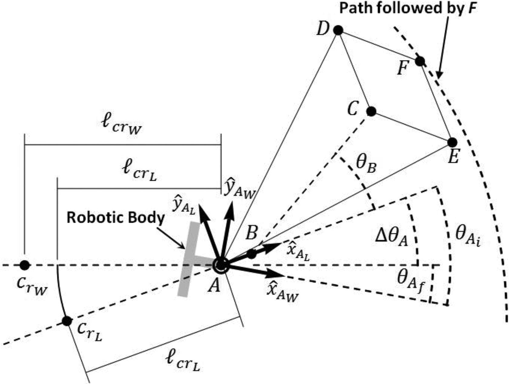
The ability to trace a concave or a convex circular arc implies the existence of a center of rotation, which is collinear to points A and B. Remember that the proximity of the center of rotation depends on rc, keeping kAC constant. It is important to emphasize that there are now two centers of rotation: the one corresponding to the center of rotation of point F, which we call as crL, and the center of rotation that the walking machine must move around, named crW (see Figures 11 and 12). In most cases, they do not match. To overcome this discrepancy, it is necessary to include another degree of freedom. In Figures 11 and 12, we show a PL-based leg joined to the main body of the walking machine at point A. In Figure 11, we express the necessity of making crL and crW match, when the robotic leg faces a problem concerning case 2. In Figure 12, the sprawling leg confronts a problem dealing with case 3.
The RCT process, dealing with case 2. RCT: rotation center tuning.

The RCT process, dealing with case 3. RCT: rotation center tuning.
To make both centers of rotation coincident, it is necessary to perform two actions. The first one concerns the adjustment of the distance found between points A and crL, which must be equal to the distance between points A and crW. The second one deals with the fact that the lines between points A and crL and between points A and crW must be collinear. The last action involves the joint variable θA, representing the fourth DOF, and it is driven by a rotary actuator that makes link
In summary, to execute an RCT process, it is necessary to use 3-DOFs; they are represented by dAB, dBC, and θA. The first two joint variables determine the exact ratio rc, which is involved in the correct choice of concave or convex arcs. Then, dAB and dBC are dedicated to nullify
In Figures 11 and 12, we show an additional reference frame called 

Once an RCT process is complete and ready, the PL-based leg performs the walking gait. However, when θB evolves, point F traces a path on the plane where points A, B, C, D, and E exist. This plane coincides with the one generated by

The fifth DOF helps to raise or lower the robotic foot. DOF: degrees-of-freedom.
In this manner, gait employs 2-DOFs, θB and dF. The first one helps to achieve all those coordinates referred to

Three DOFs are employed in the RCT process and 2-DOFs perform gait. RCT: rotation center tuning; DOF: degrees-of-freedom.
Kinematics
On one hand, Núñez-Altamirano et al.
32
present the direct and inverse kinematics of a PL-based leg in terms of a three-point bordered path. They describe how the robotic leg adapts its linkage in terms of the curvature of the road, obtained by three points placed on the contour of the road, but they do not offer details about gait in consideration of the work space. Thus, the analysis is restricted to the DOFs that are employed in adapting the leg to follow concave or convex curves. On the other hand, Núñez-Altamirano et al.
33
offer the forward and inverse kinematics, as well as the dynamics, of the PL-based leg when it executes a linear path (
To position the foot in the 3-D space, according to a prescribed path imposed upon the walking machine, the reptilian leg carries out two tasks: (a) the RCT process and (b) gait (Figure 14). Given that the first one enables the leg to follow a path, it must precede the second one.
Once the RCT process is executed, gait is performed with the use of θB and dF, depending on the position of the foot, which is restricted to moving on a flat or cylindrical surface, as shown in Figure 15. This task depends on cases 1, 2, or 3.

Workspaces of the robotic foot corresponding to cases 1–3. They are surfaces formed by the evolution of θB and dF.
Every point on the surfaces is the input datum, which enables the determining of θB and dF. We use the cylindrical coordinates ρ, ϕ, and hfoot. The first one is the radius of curvature; the second is the angle produced between the line of action of
The most powerful skill of this reptilian robotic leg is adapting its structure to a specific center of rotation, providing circular concave or convex arcs. Consequently, its kinematics is strongly influenced by the description of point crw
on the plane defined by
Hence dAB, dBC, and θA must be determined in terms of the center of rotation of the machine. The joint variables dAB and dBC are obtained by (7) to (9), where ℓcr is the distance, measured on the plane generated by 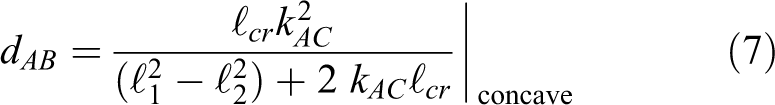


Taking into account 
Once dAB, dBC, and ΔθA have been determined and gait is performed by θB and dF. The joint variable θB is defined in terms of the operational coordinate ϕ, see (11). Notice that a = ρϕ defines the arc that point F has achieved during gait
where
and
Finally, dF depends on the operational coordinate hfoot as shown in (14). Because the reptilian foot is always placed below the plane formed by 
Path-planning procedure
The next procedure summarizes the course of action presented in the subsequent simulation process. The whole path planning implies the RCT process planning and the gait planning. The RCT process initiates Data acquisition concerning the center of rotation of the walking machine Definition of the trajectory planning dealing with the RCT process, which concerns the path and the time profile. It implies the definition of xcr and ycr, along a prescribed path, in terms of n (it could be denoted as a function of time). The achievement of the flight phase condition The simultaneous evolution over time of θA and rc, with the restrictions given by (2) and the trajectory planning, until The RCT process ends The gait initiates Definition of the path followed by the robotic foot. It implies the description of the parametric Cartesian coordinates xpath, ypath, and zpath as function of m, projected onto the cylindrical workspace. The parameter m could be described by a time profile. The simultaneous evolution of θB and dF, with the restrictions given by the trajectory planning. The gait ends
Simulation
To make the above theoretical framework comprehensible, we present the simulation of an example, focusing on the RCT process and the walking gait. The example includes the design of an elliptical path, which is projected onto the cylindrical workspace, concerning a concave case, and is followed by the reptilian foot in terms of two parameters. The first one concerns the RCT process and the second one deals with gait.
On the one hand, convex tasks are similar to the cases shown herein and we consider that the explanation provided is sufficient. On the other hand, problems dealing with case 1 do not require an RCT process, because
Conditions of the simulation
The sprawling robotic leg specimen, based on the one presented in this article, is defined from the parameters given in Table 2. It is important to note that symbol (L), in this example, means any unit of length.
Lengths of links, heights, and kAC.

L: a unit of length.
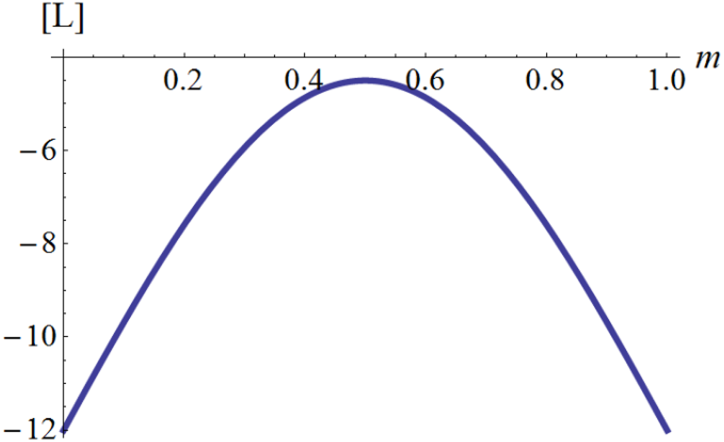
We present the evolutions of dAB, dBC, θA, θB, and dF when the foot of the reptilian leg is required to follow the path presented in Figures 16 and 21, whose parametric Cartesian coordinates are presented in (15) to (17), corresponding to an elliptical curve projected onto the cylindrical surface representing the workspace. Such parametric Cartesian coordinates are referred to {AL} at the end of the RCT process and are controlled by parameter 


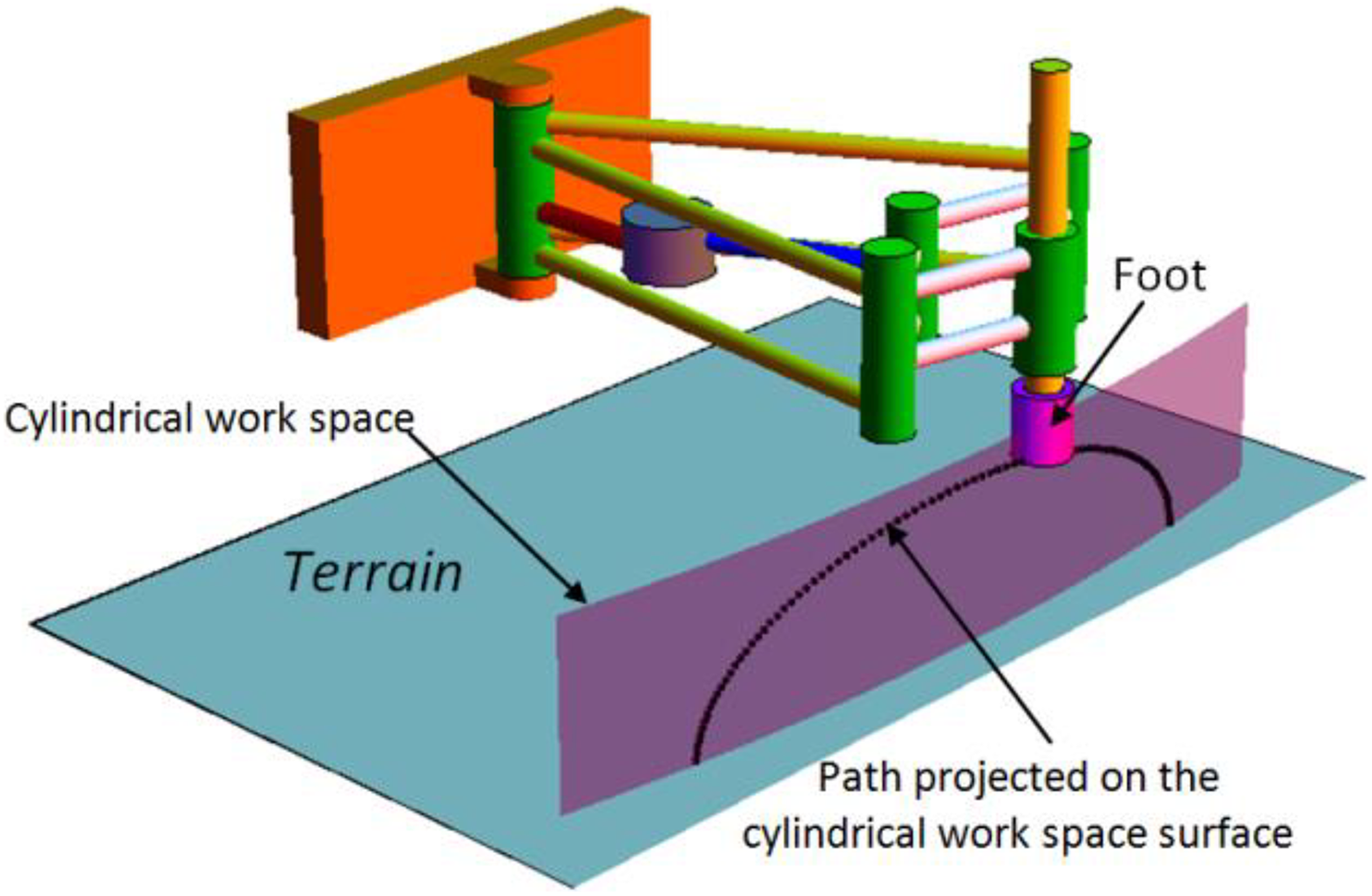
Elliptical path followed by the reptilian leg. It is projected upon the cylindrical workspace concerning this example.
Given that θB and dF are obtained in terms of ϕ and hfoot 

If (18) and (19) are substituted in (11) and (14), respectively, then we obtain θB and dF in terms of m, and their evolutions are achieved when
In this simulation, we consider that the points of centers of rotation, referred to 

Parameters m and n could be governed by time law profiles as it was described in the previous section, but the aim of this simulation process intends to show how the RCT process and the gait are performed instead of the mere evolution in time of the joint variables.
Results
Table 3 presents the results corresponding to the postures of the reptilian leg when it is adapted to
The reptilian leg at the beginning and at the end.

L: a unit of length.
Points
Figures 17 and 18 show the evolutions of dAB, dBC, and θA in terms of

Evolution of dAB and dBC with respect to

Evolution of θA and
Once n = 1, the foot of the reptilian leg is prepared to follow the path presented in Figures 16 and 21. Because the reptilian leg adapts its posture during the RCT process, the foot does not touch the terrain during said adaptation. So, gait begins only when the RCT process has completely finished.
Graphics shown in Figures 19 and 20 present the evolutions of θB and dF, respectively. Both are controlled and coordinated by

Evolution of θB with respect to
Evolution of dF with respect to
In Figure 21, we present a sequence of 11 postures when parameter m varies from 0.0 to 1.0, at every 0.1. It is clear that the reptilian robotic foot follows the elliptical path, which is projected onto the cylindrical concave surface, corresponding to

A sequence of 11 postures when
Discussion
Mechanical structure
Because a reptilian sprawling leg is affected by large joint moments and muscle forces, acting on the proximal part of the limb, we have designed a strong mechanical architecture, in which revolute joint axes have the same direction as gravity forces. Thus, linear and rotary actuators, associated with dAB, dBC, θA, and θB, have only to overcome the forces parallel to the frontal plane and the torques parallel to the sagittal one. Moments and forces acting on joints react upon stiff materials and are supported by strong ball bearings. The proximal part of the limb is based on two PL linkages, which are parallel and connected by strong vertical axes passing at points A, C, D, E, and F. Actuators associated with dAB, dBC, and θB are sandwiched by those two PL linkages. This mechanical arrangement intends to achieve a stiff and light structure, providing low deformability under moments and forces and low inertia, 34 according to a reptilian robotic leg.
Advantages and disadvantages
The 5-DOF sprawling robotic leg, based on the 1-DOF PL mechanism, is a redundant robotic limb, and its redundancy is used to obtain a more versatile positioning device in terms of its kinematical configuration and its interaction with the environment. 35 Thus, redundancy can be seen as an advantage because it is a source of freedom in task execution, since it provides the robot mechanism with an increased level of dexterity. 36 Nevertheless, redundancy implies higher energy consumption because of the number of actuators; this is a disadvantage.
If a walking machine, equipped with sprawling robotic legs based on PL mechanisms, moves along a circular path with a constant center of rotation, the actuators dedicated to the RCT process remain motionless, and the only actuators that move are those dedicated to walking, then this represents an advantage from the point of view of control, because it is easier to coordinate one or two actuators, instead of three, that are necessary in traditional robotic legs. If the sprawling robotic leg moves in flight phase, when the reptilian foot ascends or descends, the controller coordinates two actuators. But, in support phase, when the main body of the walking machine is positioned at a constant height, the controller drives only one actuator. In our opinion, it is the strongest advantage of this leg. We compare this skill in front of those of two of the most representative sprawling-legged robots: Pleurobot and TITAN-XIII.
Pleurobot is a sprawling posture robot with four legs and each one has 4-DOFs. 37 It means that its legs are redundant for the task of positioning its feet in the 3-D space. In order to trace an exact straight or circular path, its controller needs to coordinate a set of four motors per leg. This task is more complicated than the one concerning the PL-based leg, which uses only 1- or 2-DOFs to perform the gait after the RCT process.
TITAN-XIII is a four-legged robot whose leg unit has 3-DOFs. 6 It consists of a planar mechanism with 2-DOFs and an additional one, employed to orientate the planar linkage. Due to the nature of the leg unit, the gait requires the simultaneous control of the total set of actuators.
In Figure 22, we show a traditional sprawling legged robot with traditional zoomorphic legs. In order to position its feet, it requires 3-DOFs per leg, which are represented by cylinders, denoting revolute joints.

Traditional sprawling walking robot with zoomorphic legs.
In Figure 23, we show one of the legs of the sprawling robot shown in Figure 22. It performs the same path as the one shown in Figures 16 and 21. Due to the fact that the RCT process and the gait are decoupled, the process of control, concerning a PL-based leg, could be easier than the zoomorphic one. It is very clear that the traditional zoomorphic leg needs to actuate and control the total set of motors per leg. The PL-based leg shown in Figure 21 actuates and controls only two of their motor.

A dynamic sequence of motion of a traditional sprawling leg.
The advantage is more remarkable if the path followed by the foot is confined to constant hfoot and hW; the PL-based leg moves only one of their actuators, because dF remains constant. Conversely, the zoomorphic leg invariably moves their three actuators for the same task. A condition when hfoot is constant occurs when the leg is in support phase. In this case
Conclusions
We have designed a non-traditional robotic leg and simulated its kinematic skills in relation to the attributes of reptilian sprawling legs. For its conception, we employed the 1-DOF PL mechanism, which was transformed by including four more DOFs. The resulting positioning device is able to move its foot along paths on cylinder-shaped and flat workspaces.
An important contribution deals with concavity and convexity. These two concepts have permitted the use of the PL linkage as the basis of the reptilian leg. Not only do robotic legs enable the walking machine to move along straight paths, but they also allow it to walk along different axes of rotation. Every reptilian leg joined to the walking machine must adapt its posture according to each particular circumstance. Regarding a required center of rotation, some of the legs are prepared to follow concave curves, while others are disposed to trace convex paths.
The inverse kinematic analysis is divided into two parts. The first one considers the 3-DOFs dedicated to preparing the leg to follow straight or curved paths. The second one is concerned with the DOFs employed in gait. The reptilian robotic leg utilizes the centers of rotation that the robotic machine walks around, by means of a process called RCT. After this process, the reptilian robotic leg uses only 2-DOFs. In contrast to most robotic legs with traditional mechanical architectures that use at least 3-DOFs during gait, the use of only 2-DOFs appears to be advantageous. All paths are compounded by a series of distinct curves, defined by their own centers of rotation. In this regard, the main attribute of the leg presented herein is to trace circular arcs with only one actuator, once it is reconfigured, greatly reducing control complexity. The combination of this actuator and the one employed to ascend or descend the foot provides the necessary gait to make the machine move along the prescribed path. It is undoubtedly easier to control two actuators rather than the three that are employed in traditional zoomorphic legs.
One difficulty in implementing the proposed design was to find the way to introduce five actuators and three prismatic joints among a tangle of links that cross certain joint axes during their movement, while at the same time, maintaining a stiff structure, capable of supporting its own weight and the payload. Despite this entanglement of links, the presence of several bars allowed good distribution of the total load across the entire strong structure.
Footnotes
Declaration of conflicting interests
The author(s) declared no potential conflicts of interest with respect to the research, authorship, and/or publication of this article.
Funding
The author(s) received no financial support for the research, authorship, and/or publication of this article.