
Abstract
Image-based visual servoing (IBVS) has increasingly gained popularity and has been adopted in applications such as industrial robots, quadrotors, and unmanned aerial vehicles. When exploiting IBVS, the image feature velocity command obtained from the visual loop controller is converted to the velocity command of the workspace through the interaction matrix so as to converge image feature error. However, issues such as the noise/disturbance arising from image processing and the smoothness of image feature command are often overlooked in the design of the visual loop controller, especially in a contour following task. In particular, noise in the image feature will contaminate the image feedback signal so that the visual loop performance can be substantially affected. To cope with the aforementioned problem, this article employs the sliding mode controller to suppress the adverse effects caused by image feature noise. Moreover, by exploiting the idea of motion planning, a parametric curve interpolator is developed to generate smooth image feature commands. In addition, a depth observer is also designed to provide the depth information essential in the implementation of the interaction matrix. In order to assess the feasibility of the proposed approach, a two-degrees-of-freedom planar robot that employs an IBVS structure and an eye-to-hand camera configuration is used to conduct a contour following task. Contour following results verify the effectiveness of the proposed approach.
Keywords
Introduction
Recently, image-based visual servoing (IBVS) has increasingly gained popularity over the past two decades and has been adopted in applications such as industrial manufacturing, 1 –3 quadrotors, unmanned aerial vehicles, 4,5 industrial robots, and mobile robots. 6,7 Several challenging problems related to IBVS remain unsolved. 8 Many existing studies related to IBVS focus on the transformation problems between different spaces such as the singularity problem and decoupling problem for image Jacobian, 9 while some investigate stability and convergence issues in IBVS. 10 Moreover, if the direct IBVS structure is adopted, 1 dynamics issues in visual servoing such as path/trajectory planning, visual loop controller design, and depth estimation need to be further explored. 11
Vision-based path-planning problems in visual servoing applications are often encountered in point-to-point motions and contour following motions. 12 In particular, one can divide vision-based path planning into two categories—offline path planning and online path planning. For offline path planning, Cherubini et al. 6 developed an IBVS scheme for nonholonomic robots to follow a continuous path drawn on the ground. In Chang et al., 13 the path command for an unknown planar shape contour following task is generated by a Pythagorean-hodograph (PH)-spline interpolator. In Chang, 14 a binocular camera is adopted in a three-dimensional (3D) contour following application and the correspondence feature mapping problem in binocular systems is also addressed. On the other hand, for online path planning, Mezouar and Chaumette 15,16 proposed a new approach that performs path planning in an image space for IBVS. In particular, specific constraints are made to develop an interpolator ensuring that certain goals, such as ensuring the object remains in the field of view (FOV) of the camera and avoiding the joint limits of the robot, can be achieved. Later, Schramm and Morel 17 proposed a camera-parameter-free approach that can provide analytical solutions to the path-planning problem of the feature points in the image plane. Kyrki et al. 18 proposed a shortest-path approach for visual servoing to guarantee both the shortest Cartesian trajectory and object visibility. Under the assumption that the camera pose has been estimated and taking into account issues such as workspace, joint limits, and visibility margin, Chesi and Hung 19 proposed an optimal path-planning approach in the image space for an IBVS controller. Kazemi et al. 20 further proposed a global path-planning approach that accounts for constraints such as visibility of the target, visual occlusion avoidance, collision avoidance, and joint limits, in which the generated camera path is projected into the image space to be used in an IBVS scheme. Sharma and Hutchinson 21 proposed the concept of motion perceptibility and applied it to the problems of active camera trajectory planning and simultaneous camera/robot trajectory planning.
In IBVS, as mentioned previously, several challenging issues such as control design of visual loop and depth estimation deserve further investigation. In DeLuca et al., 22 a nonlinear observer is exploited to estimate the depth value that is essential in the calculation of the interaction matrix in an IBVS scheme. In Keshmiri et al., 23 unlike most previous approaches generating velocity commands for robot controllers, in order to achieve smoother feature tracking results, an augmented IBVS controller is proposed to generate acceleration commands for robot controllers instead. Becerra et al. 24 proposed a sliding mode controller that uses desired epipole trajectories for an IBVS scheme to achieve robust global stabilization without the need of performing accurate camera calibration. In order to avoid system failures when feature points are not in the FOV of the camera, Gans and Hutchinson 25 proposed a hybrid visual servo approach that switches between position-based visual servoing and IBVS. Jiang et al. 26 proposed an indirect Iterative Learning Control scheme for vision-guided robots to perform the task of trajectory imitation, in which the unknown interaction matrix essential to implementing IBVS is approximated by a series of neural networks so as to avoid possible singularities in uncalibrated (or poorly calibrated) camera applications.
Due to the fact that the issues of system dynamics and nonlinearities are crucial in the design of a direct IBVS scheme, this article focuses on enhancing the performance of the direct IBVS scheme so as to improve the entire visual servoing system. The contributions of this article are twofold (as shown in Figure 1): Control block diagram for the direct IBVS scheme employed in this article. IBVS: image-based visual servoing. By exploiting the concept of acceleration/deceleration motion planning commonly adopted in motion control applications, smooth image feature commands to be used in a direct IBVS scheme can be generated by a parametric curve interpolator. In addition, a depth observer
22
is also designed to provide the estimated depth value to the direct IBVS scheme in real time so that the actual image trajectory can be properly controlled to converge to the desired feature trajectory in the image space.
27
Since the sliding mode control (SMC) is a nonlinear control method that can increase the robustness and disturbance suppression ability of the control system, in this article, a sliding mode visual loop controller is designed to cope with the possible contour following accuracy problems caused by modeling error/image feature noise.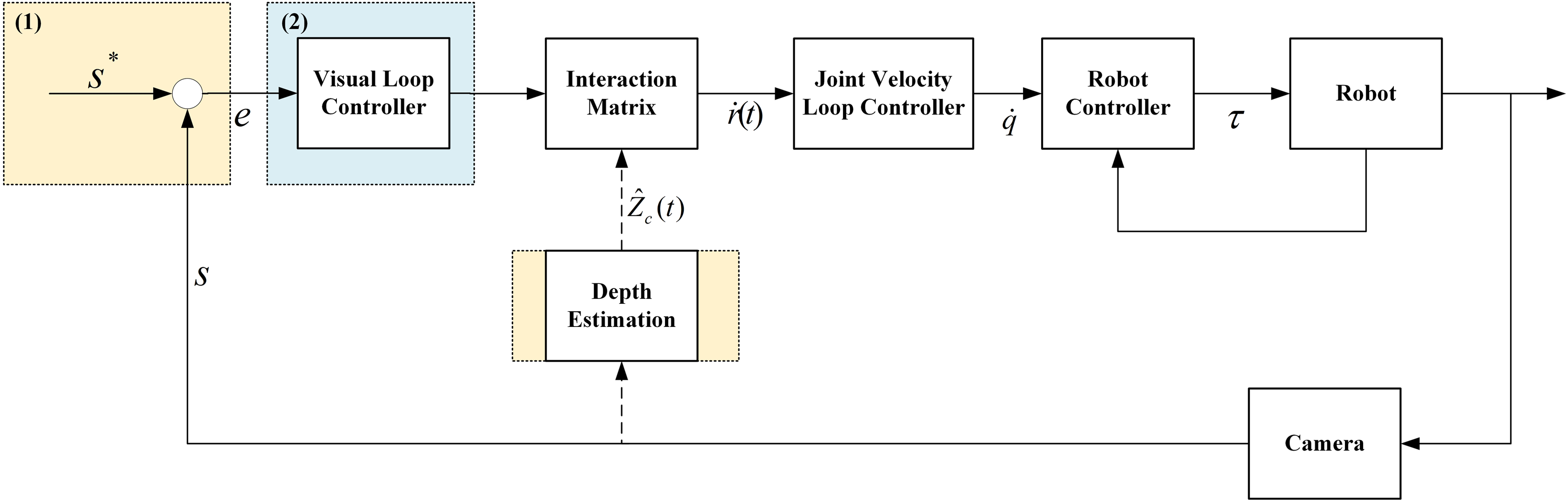
In order to verify the effectiveness of the proposed approach, an experimental platform consisting of a two-degrees-of-freedom (2-DOF) planar manipulator equipped with an eye-to-hand camera is used to perform a vision-based contour following motion with respect to an object without a known geometric model.
The remainder of the article is organized as follows. The “Problem statement” section lays out the dynamics issues encountered in designing IBVS. The issues concerning image feature command generation, target image detection, and depth observer are addressed in the “Image-based path planning with a depth observer” section. Design of the direct IBVS controller is included in the “Direct IBVS controller design” section. Experimental setup and results are provided in the “Experimental setups and results” section. Finally, the conclusions are summarized in the “Conclusions” section.
Problem statement
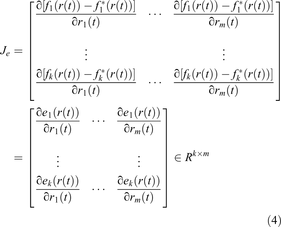
Suppose in an image contour following task, the desired image feature command is obtained through a parametric curve interpolator. Without the loss of generality, the desired image feature command can be expressed as f*(r(t)). In general, an IBVS control scheme is designed to converge the tracking error e(r(t)) between the vector of the desired image feature f*(r(t)) and the vector of the image feature f(r(t)). Taking the derivative of e(r(t)) with respect to time t will yield

where
In addition,


where r(t) are the coordinates of end effector in some parameterization of task space T;
Note that all three interaction matrices are functions of the depth values of the feature points in the camera frame. In general, the depth values of the feature points in the camera frame are not known and need to be estimated. The accuracy of the estimated depth value affects the accuracy of the interaction matrices as well as the performance of IBVS. 9 Suppose that the visual loop controller is of P type. That is, the image feature error e(r(t)) is controlled to exponentially converge to zero as described by

where λ is the gain constant of the P-type visual loop controller.
Substituting equation (1) into equation (5) will yield

Suppose that the matrix

The velocity screw is then converted into the joint velocity command

Moreover, this article focuses on the control design problem of a direct IBVS scheme. With the joint velocity command obtained from equation (8), one can design a joint velocity loop controller for generating the torque command to the servomotors installed at each joint of the robot, as shown in Figure 1.
Image-based path planning with a depth observer
In this article, motion planning is performed on a desired contour in the image plane. Moreover, with the depth information provided by a depth observer and a properly designed visual loop controller, the actual image contour can be controlled to converge to the desired image contour, as shown in Figure 2.
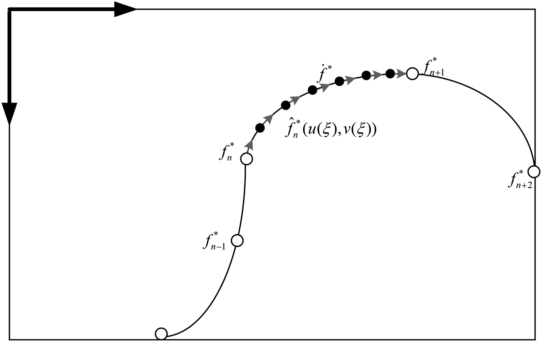
With the depth information provided by a depth observer, the actual image contour can be controlled to converge to the desired contour.
In Figure 2,

Denote

Equation (9) can be rewritten as

Equation (11) is an ordinary differential equation for ξ(t) and can be solved by a numerical method such as the Taylor first-order method, the Taylor second order method, and the Runge–Kutta method.
35
After the parameter value ξ(t) at time t is known, one can calculate the desired image feature point

where μ is the calibrated focal length in pixels and the state vector
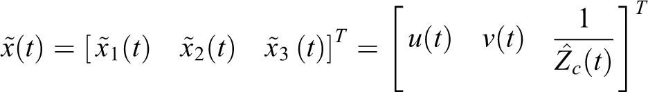
The updated equation for the estimation of the unknown state is described by equation (13), where


where

Figure 3 illustrates the block diagram for the proposed depth estimation approach based on the parametric curve.

Block diagram for the proposed depth estimation approach based on the parametric curve.
Direct IBVS controller design
SMC is one of the most commonly used nonlinear control schemes that can increase the robustness and the disturbance suppression ability of the control system. SMC belongs to the category of variable structure control
36
and has several attractive features such as simple controller design, good dynamic response, being robust, and having excellent disturbance suppression ability. In SMC, a sliding surface should be chosen in advance. Based on the system state, the sliding model control law generates switching force and equivalent force. In particular, the switching force makes the dynamics “slide” to the predefined sliding surface, while the equivalent force keeps the states of the system on the sliding surface after these states intersect the sliding surface. Under proper design, the SMC can guarantee asymptotic stability. In this article, an SMC is adopted in the design of the visual loop controller to reduce the image feature error e between image feature measurement f(t) and desired image feature
Suppose that in equation (1), the desired image feature
Differentiating equation (17) will result in

where
In this article, the control output vc of the SMC is described by

where vs is the switching control and ve is the equivalent control.
In particular, when the system state is on a sliding surface, that is, S = 0, the equivalent control can be obtained by letting

In contrast, when the system state is not on a sliding surface, that is, S≠0, the switching control is activated to drive the system toward the sliding surface.
To derive the switching control law, consider the following Lyapunov function candidate
Clearly, V(t) is positive definite. The derivative of V(t) versus t along the system trajectory is

Substituting equation (18) into equation (22) will yield

In addition, substituting equations (19) and (20) into equation (23) will result in

By choosing the switching control law vs = −Ks sgn(S), equation (24) becomes

where Ks ∈ ℜ2×2 is a positive definite constant gain matrix.
According to the Lyapunov stability theorem, the system under SMC is stable. 37,38
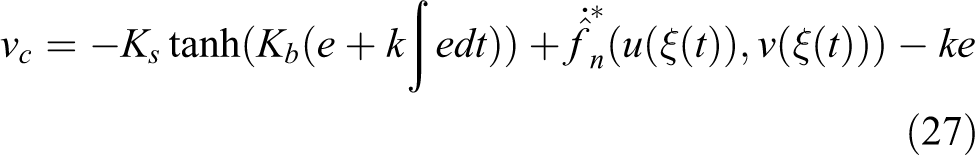
However, the switching control vs contains a signum function that often results in the so-called chattering phenomenon. In order to cope with this problem, a hyperbolic tangent function tanh(•) is adopted to replace the signum function so as to smoothen the switching control. That is

where Kb ∈ ℜ2×2 is a positive definite constant gain matrix.
Substituting equations (20) and (26) into equation (19) will result in
In addition, since

where
Experimental setups and results
The experimental platform consisting of a 2-DOF planar robot equipped with an eye-to-hand camera, a personal computer, and an IMP-2 motion control card by ITRI, Taiwan, ROC, as shown in Figure 4, is used to assess the performance of the proposed approach. The two joints of the planar robot are actuated by two AC servomotors, ECMA-C10804E7 and ECMA-C10602AS (Delta electronics, Taiwan). Throughout the experiments, the motor drives of the AC servomotors are set to torque mode. In addition, each servomotor is coupled with a 1:50 planetary gear reducer. The resolution of the encoder is 10,000 pulses/rev. In addition, the eye-to-hand camera is an FLEA3 FL3-U3-13E4C-C camera of resolution 640 pixel × 512 pixel and frame rate of 60 Hz (Point Grey, Canada). Its SV-1614 V lens with a focus length of 16 mm is manufactured by VS Technology (Japan).

Experimental platform consisting of a 2-DOF planar robot equipped with an eye-to-hand camera, a personal computer, and an IMP-2 motion control card by Industrial Technology Research Institute (ITRI). DOF: degree of freedom.
Throughout the experiments, the geometric model of the object is not known in advance. The exterior contour of the object on the image plane is extracted, as shown in Figure 5. However, the extracted contour consists of pixels (i.e. grid points) in the image plane. Very likely, the pixels on the extracted contour are not dense enough to be directly used as the desired image feature commands in IBVS. In order to cope with this problem, as discussed in the “Image-based path planning with a depth observer” section, in this article a PH spline is constructed to pass through all the pixels on the extracted exterior contour of the object in the image plane. Moreover, with the desired feed rate provided, a parametric curve interpolator is developed to generate smooth desired image feature commands based on the constructed PH spline. Several contour following experiments are conducted to compare the performance of two visual loop controllers and to assess the effectiveness of the depth observer.

Extraction of the exterior contour of an object on the image plane.
Performance comparison of visual loop controllers
In the contour following experiment, the tip of the planar robot is controlled to move along the contour of the object on the image plane. As mentioned previously, the geometric model of the object is not known in advance. By using the methods introduced in the “Image-based path planning with a depth observer” section, the generation of the desired image feature command and the detection of the vision feedback signal can be accomplished. In each experiment, two different visual loop controllers in IBVS—a PI controller and a sliding mode controller—are tested. In the experiments, a fixed depth value is used in the calculation of the interaction matrix. For each visual loop control scheme, ten contour following experiments are conducted. Note that the sampling rate for the visual loop is 50 Hz, and the desired feed rate for the parametric curve interpolator is 60 pixel/s. The cycle time of one contour following experiment is 17.36 s, indicating that there are a total of 868 image feature command points used in the contour following experiment. In order to observe the steady state response, two cycles of contour following motions are executed and only the results of the second cycle will be analyzed.
Figure 6 shows the contour following results of the PI-type visual loop controller, while Figure 7 shows the contour following results of the sliding mode visual loop controller. Clearly, the sliding mode visual loop controller yields significantly smaller contour error around the portion of the contour with large curvature. Figure 8 shows the average tracking error and contour errors of ten contour following experiments for two tested visual loop control schemes. It is clearly evident that the sliding mode visual loop controller outperforms the PI-type visual loop controller in all categories.
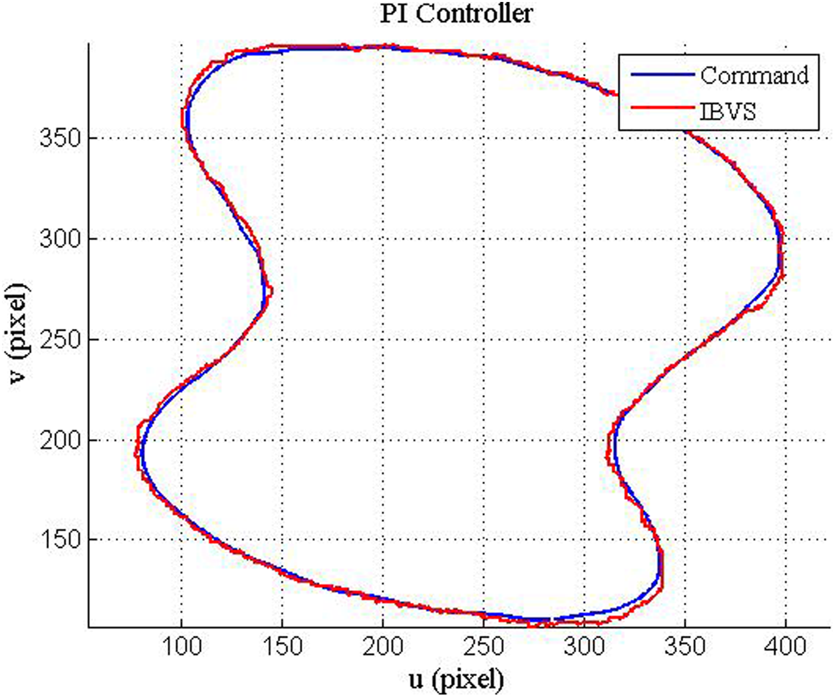
Contour following results of the Proportional-Integral-type (PI-type) visual loop controller.

Contour following results of the sliding mode visual loop controller.

Performance comparison between two different visual loop controllers.
Performance assessment of depth observer
In IBVS, the interaction matrix plays a crucial role in converting the output of the visual loop controller into the velocity screw of the end effector. However, the depth information is essential when implementing the interaction matrix. One way to estimate the current depth value is to use the depth observer. The aim of this experiment is to assess the performance of the depth observer in contour following applications. In addition, the sliding mode controller is adopted as the visual loop controller throughout this experiment. Figures 9 and 10 show the experimental results of tracking error and contour error, respectively. Figure 11 shows the average tracking error and contour errors of ten contour following experiments using a depth observer or a fixed depth value. The results shown in Figure 11 indicate that the sliding mode IBVS with a depth observer slightly outperforms the one with a fixed depth value, especially in the tracking error of image feature. Figure 12 shows snapshots of an image sequence of the contour following experiment taken for every 0.62 s.

Tracking error using (a) a fixed depth value and (b) a depth observer.

Contour error using (a) a fixed depth value and (b) a depth observer.

Average tracking error and contour errors of 10 contour following experiments.

Snapshots of an image sequence of the contour following experiment.
Conclusions
This article focuses on the dynamics performance improvement of a visual servoing system employing an IBVS structure in contour following applications. In particular, a sliding mode IBVS structure is developed in this article to deal with the external disturbance caused by modeling error and the noise in image feature measurement. In addition, in this article, the desired image feature commands are generated using a parametric curve interpolator based on the image captured by an eye-to-hand camera. Moreover, the depth information essential in the calculation of the interaction matrix is provided by a nonlinear depth observer so as to converge image feature tracking error. Results of contour following experiments of objects without known geometric models verify the effectiveness of the proposed approach.
This article focuses on the case of unknown two-dimensional planar contour following only. An extension to a more general case of 3D contour following in industrial applications is a research topic deserving of in-depth investigation in the future. In addition, in this article, a dual control loop consisting of a visual loop and robot control loop is adopted. The pros and cons of using single sampling rate or dual sampling rate for the control scheme in a visual servoing system need to be further addressed as well.
Footnotes
Declaration of conflicting interests
The author(s) declared no potential conflicts of interest with respect to the research, authorship, and/or publication of this article.
Funding
The author(s) disclosed receipt of the following financial support for the research, authorship, and/or publication of this article: The project is supported by the National Science Council of the Republic of China, Taiwan, under grant no. MOST 103-2221-E-006-185-MY2.