
Abstract
The existing methodologies employed for the quantification and regulation of tractor’s tillage depth present considerable shortcomings, primarily characterized by their low accuracy and poor disturbance rejection proficiency in complex agricultural terrains. In this study, we present a sophisticated feedback control strategy designed to mitigate these challenges. Our innovative approach hinges on calculating tillage depth from the alignment of the tractor’s hydraulic lifting arm, achieved by employing a mechanical angle sensor. This sensor adeptly gages the angle of the lifting arm, aligning it with the tillage angle of the pull rod and the implement’s angle, resulting in a robust relational model correlating the lifting arm angle with the tillage depth. This pioneering method amalgamates the accuracy inherent in the static model, derived from the tillage angle-based depth measurement, with the dynamic stability afforded by the mechanical ascertainment of the lifting arm angle. In conjunction, we introduce a Hybrid Extended State Observer-Based Backstepping Sliding Mode Controller (HESO-BacksteppingSMC). The HESO is instrumental in estimating unmeasured state variables and lumped disturbances, utilizing the system’s output feedback signal. Our control frame component capitalizes on the fast power-reaching law to yield a continuously smooth control signal, effectively eradicating the conventional chattering phenomenon inherent in controllers and amplifying its functional applicability. Theoretical evaluations affirm the uniformly and ultimately bounded stability of the errors associated with our proposed observer and controller, underscoring their robustness. The superior performance of our proposed tillage depth measurement and control methodology has been corroborated through a series of comprehensive simulation and field plowing trials, attesting to its precision and reliability in complex agricultural settings.
Keywords
Introduction
Tillage, as a major agronomic process, has a profound impact on the physical, chemical, and biological properties of the soil, thereby considerably influencing the health and productivity of agricultural ecosystems.1–4 Tillage depth serves as a vital parameter in evaluating the efficacy of the tillage process.5,6 Adjusting and maintaining uniformity in tillage depth is imperative and depends on factors such as crop varieties, tillage methods, and soil consistency to optimize crop production. 7 Autonomous tractor plowing can elevate the efficiency and quality of tillage. The incorporation of autonomous operations in field tilling offers marked improvements in both efficiency and tilling quality. Consequently, delving into online depth measurement and automatic control in tractor plowing is of paramount importance for advancing agricultural field standards.
The capacity to measure tillage depth in real time is fundamental to the attainment of autonomous control over tillage depth. 8 Conventional tillage depth measurement techniques involve the selection of sample points in the field and excavating the soil for measurement using instruments such as tillage depth gages, a process which is labor-intensive, inefficient, and lacks continuous measurement capabilities.7,9 Over recent years, many scholars have conducted comprehensive research into real-time tillage depth measurement methodologies.10–14 For instance, Lou et al. employed the propagation time interval of ultrasonic sensor signals to compute the distance between the implement and the ground, thus facilitating tillage depth measurement. 6 Kim et al. affixed a self-designed fixture fitted with an inclinometer at the base of the suspension mechanism, measuring the inclination angle change of the fixture and combining it with the fixture’s geometric parameters to accomplish tillage depth measurement. 11 Xie et al. achieved real-time measurement of the plowing depth of the implement by calibrating the coupling relationship parameters between the inertial inclination sensor installed on the lifting arm of the suspension mechanism and the plowing depth. 13 The tillage depth measurement method based on angle measurement is more convenient for large-scale promotion and application due to its advantages of high accuracy, easy installation, and no environmental restrictions. Nonetheless, elements such as rotation, maneuverability, and vibration during tractor tillage operations could potentially impair the performance of tillage angle detection, subsequently leading to a reduction in tillage depth measurement accuracy. Hence, further exploration is required for more precise and stable tillage depth measurement techniques.
Additionally, academic research in tractor tillage depth control has been extensive in recent years.15–17 Serhat and Carman achieved automatic adjustment of tillage depth by measuring the slip ratio during tractor tillage operations and applying a fuzzy control system, thereby boosting the efficiency of tractor plowing. 15 Gao et al. designed a variable-domain fuzzy proportional-integral-derivative controller (PID) based on the depth error and its rate, which demonstrated faster and more stable performance compared to conventional PID controllers and fuzzy PID controllers. 16 Despite the advances in tillage depth control system, the system essentially remain intricate nonlinear and underactuated systems that are subject to time-varying disturbances. Consequently, the robustness and control precision of PID controllers are found lacking. Given the rapid progress in intelligent algorithms, PID controllers are progressively being supplanted by more advanced algorithms. Notably, the backstepping method, lauded for its unique ability to address nonlinear control problems, has garnered substantial academic interest in recent years.18–22 This method disassembles the complicated nonlinear system into several subsystems, devising different Lyapunov functions to acquire virtual control laws for these subsystems. The virtual control law of the preceding subsystem then serves as the tracking target for the following subsystem. However, it’s important to note that the backstepping method often relies on an accurate model, which is challenging to establish in extreme environments. The sliding mode algorithm, renowned for its high robustness, precision, and straightforward design, is widely employed.23–30 Feng et al. introduced an adaptive sliding mode control strategy, underpinned by radial basis function neural networks, aimed at augmenting the efficacy of a robotic excavator’s performance. 31 Concurrently, Ji et al. constructed an adaptive second-order sliding mode controller purposed to refine the path tracking precision of agricultural vehicles maneuvering through intricate terrain, providing a solution to the underactuated predicament in path tracking. 32 Mechali et al. designed a novel nonlinear homogeneous nonsingular terminal sliding surface to ensure global asymptotic stability and fixed-time convergence of the system states. 33 Won et al. conceived an integral sliding mode controller, rooted in a high-gain observer, intended for enhanced position control of electrohydraulic servo systems. 34 Nevertheless, the stand-alone sliding mode controllers are marred by shortcomings, including the chattering phenomenon and the demand for comprehensive state feedback. 35 In the context of the tillage depth control system’s model, it is paramount to incorporate not only first-order position data but also specific information regarding velocity and acceleration. However, practical application faces challenges arising from rapid tractor movements and the high-frequency vibrations of plows. These challenges, coupled with limitations in sensor sampling frequency and efficiency, lead to a scenario where the system can only provide feedback on position data. The extended state observer (ESO), first proposed by Han and broadly employed for various observations, proves adept at estimating both the system state variables and cumulative disturbances. 36 However, its efficacy is limited in estimating large-scale disturbances, and it excels more in accurate estimation of minor disturbances. Gao took a leap by designing a linear ESO, based on nonlinear ESO, using pole configuration techniques, substantially easing the process of parameter tuning. 37 While the linear ESO stands out for its simplicity in design and exceptional performance in estimating large-scale disturbances, it falls short in estimating small-scale, high-frequency, time-varying disturbances. During tillage processes, uncertainties such as intricate road surfaces, the tractor body’s oscillations, and so on, increase the difficulty in designing control algorithms.
Based on the aforementioned considerations, it is our assertion that the existing single tillage depth measurement device and control algorithm are inadequate to meet the demands of complex operational environments. The contributions and novelties of this paper are expressed in details as follows:
We introduce a novel approach to measure tillage depth, ensuring that measurement accuracy remains uncompromised by factors like rotation, maneuverability, and vibration during tractor tillage operations. This method employs a mechanical angle sensor to gage the angle of the lifting arm, which is then correlated with the angle of the pull rod. From this, a relational model is derived between the lifting arm angle and the tillage depth value, anchored in the geometric model of tillage depth.
The traditional mechanical hydraulic valve of the tractor has been superseded by an electric hydraulic servo valve, instrumental in controlling the lift arm’s rotation. Our proposed tillage depth controller distinguishes itself from prior models by its enhanced resilience to unmodeled dynamics, unknown kinematic and dynamic parameters, and nonlinearity disturbances. This is achieved through the integration of a novel hybrid extended state observer and a back-stepping sliding mode algorithm. To counter the adverse chattering phenomenon typically associated with sliding mode control, we employ a fast power-reaching law. The HESO is capable of accurately estimating minor disturbances while maintaining a high response speed and estimation precision during sharp changes in disturbances. Significantly, our controller necessitates only the angle of the lift arm, rendering velocity and acceleration sensors redundant, thanks to the inclusion of the HESO.
Problem description
Tillage depth measurement
Accurate tillage depth measurement results are the foundation for achieving stable and autonomous tillage depth control. Currently, there are three main types of commonly used tillage depth measurement methods and models: distance measurement-based methods, mechanical installation-based methods, and tillage angle measurement-based methods.
Methods of measuring tillage depth based on distance measurement are straightforward, primarily utilizing distance sensors to assess changes in the height of implements from the ground, thereby obtaining real-time data of tillage depth. Noted for their simplicity, high precision, and ease of execution, these methods are well-positioned for broad implementation. However, their precision can be compromised by the quality of reflected signals, rendering them less effective in fields with crop residues or in paddy environments. In contrast, mechanical installation-based methods necessitate the crafting and incorporation of specific components to affix sensors on tractors or implements. By measuring angles or displacements, and establishing models correlating these metrics to tillage depth, precise measurement is achieved. Although characterized by their high accuracy, these methods are contingent on meticulous mechanical processing and installation, and susceptible to wear, which circumscirb their broader applicability. Tillage angle measurement-based approaches harness data derived from inertial tillage sensors affixed to the lifting arm of the suspension mechanism or the implement’s surface. The establishment of a geometric correlation between tillage depth and angles facilitates the determination of a tillage depth measurement model. With merits including high precision, uncomplicated installation, and insensitivity to environmental constraints, this approach is deemed apt for extensive application.
For tillage depth measurement methods grounded in tillage angle measurement, the measurement precision of implement angles during field operations directly impacts the real-time measurement efficacy of tillage depth. Scholars both domestically and internationally have pursued comprehensive research on implement attitude measurement methods based on micro-electro-mechanical systems inertial measurement unit (IMU).38,39 Nevertheless, during plowing operations, the strap-down inertial navigation system (SINS) is susceptible to external acceleration and Gauche acceleration resulting from vehicle maneuvering. As a consequence, the SINS is unable to independently and accurately extract the gravity vector information required for precise attitude estimation. This limitation, if not addressed, can lead to erroneous attitude corrections. Equations (1) to (3) provide expressions that define the maximum achievable accuracy for the pitch and roll angles of the implements under the influence of maneuver interference:


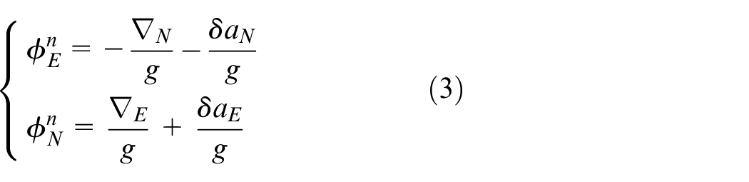
In which,
From equations (1) to (3), it can be discerned that during tractor field operations, external disturbance accelerations brought by tractor maneuvering and implement vibrations will impact the dynamic performance of implement attitude estimation. Using the measured angles of the pull rod and implement from the IMU to determine the tillage depth directly is not precise. In a static environment devoid of tractor maneuvering disturbances, the estimation results of implement attitude are only affected by the accelerometer bias of the IMU, resulting in high estimation accuracy and tillage depth measurement precision.
A single method for measuring tillage depth often proves insufficient in securing accurate results and is not directly transferable to the control of tillage depth. In light of this, our study converges the strengths inherent in both mechanical and tillage angle measurement-based approaches. We employ a dual-methodology, intertwining pull rod tillage angle measurement and implement angle measurement, to attain precise static tillage depth measurements. The lifting arm angle is assessed through a mechanical angle sensor and is subsequently correlated with both the pull rod tillage angle and the implement tillage angle. This synthesis yields a relational model between the lifting arm angle and tillage depth value. Our methodology underscores the optimal accuracy of the static model, as informed by the tillage angle-based measurement approach, whilst also inheriting the dynamic stability associated with measuring the angle of the lifting arm. The stepwise unfolding of this specific measurement process is articulated subsequently in this document.
Firstly, a geometric relationship model of the tractor tillage depth results and the geometric length with the pitch angle of the suspension mechanism is established. As shown in Figure 1, first the lengths of the pull rod
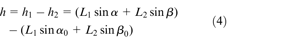
Geometric relational model of tillage depth measurement.
Secondly, the conversion relationship between the lifting arm angle and the implement pitch angle is established. From equation (4), it can be observed that the tillage depth measurement is directly related to the pitch angles of

where
Dynamic model of tillage depth control system
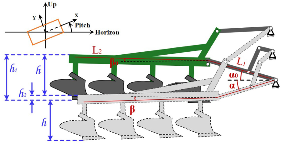
Figure 2 displays the object of control. It comprises a moldboard plow that is attached to the tractor via a lift arm, and upper and lower links. The placement of the moldboard plow is governed by an electro-hydraulic servo system that encompasses a pump, a primary valve, and a cylinder. The pump’s function is to generate a specified oil flow rate and pressure. The primary valve acts on the control signal transmitted by the controller, thereby managing the spool’s displacement. Changes in the valve’s opening directly influence oil pressure and flow, consequently controlling the cylinder’s trajectory. The cylinder, through a mechanical mechanism, is attached to the lift arm, which in turn, manipulates the position of the moldboard plow. Equation (4) illustrates the correlation between the lift arm angle and the depth of tillage.
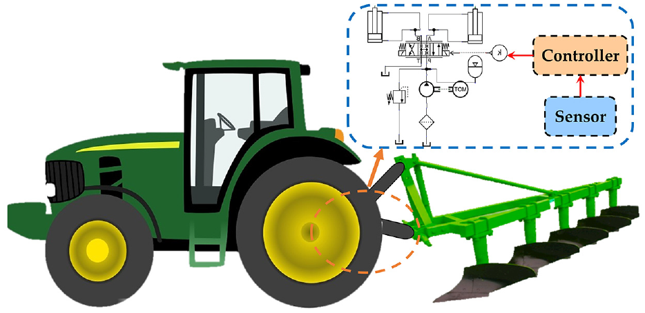
Schematic diagram of the tillage depth control system.
Our objective is to steer the plow in such a way as to expedite and enhance the accuracy of trajectory tracking of the tillage depth. This is achieved by the meticulous manipulation of the lift arm angle. Considering the three-position four-way hydraulic servo valve in the tillage depth control system, the load flow
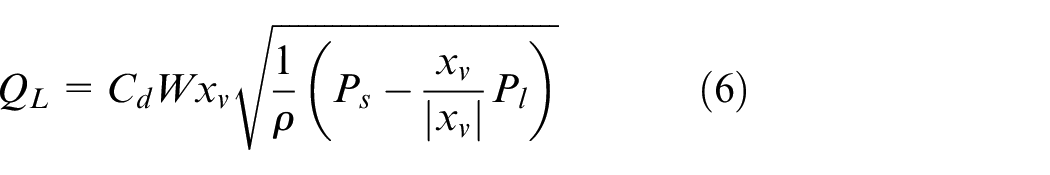
where
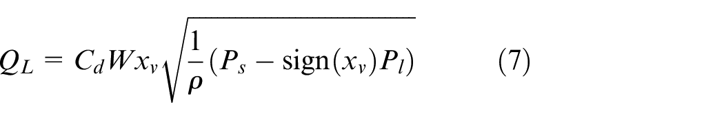
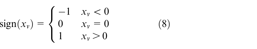
The switch function
Considering that the response frequency of the servo valve is much faster than the dynamic of the hydraulic cylinder system, it is assumed that the spool displacement
For the tillage depth control system, the force balance motion equation of the hydraulic cylinder can be obtained during the movement process of the tillage:
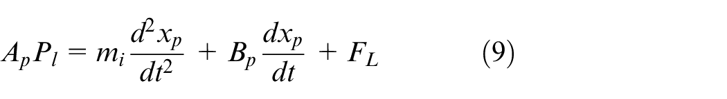
where
The pressure-flow equation of the hydraulic cylinder is written as follows:
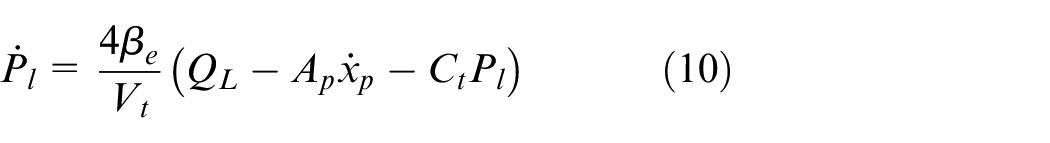
where
Considering that the piston displacement

where
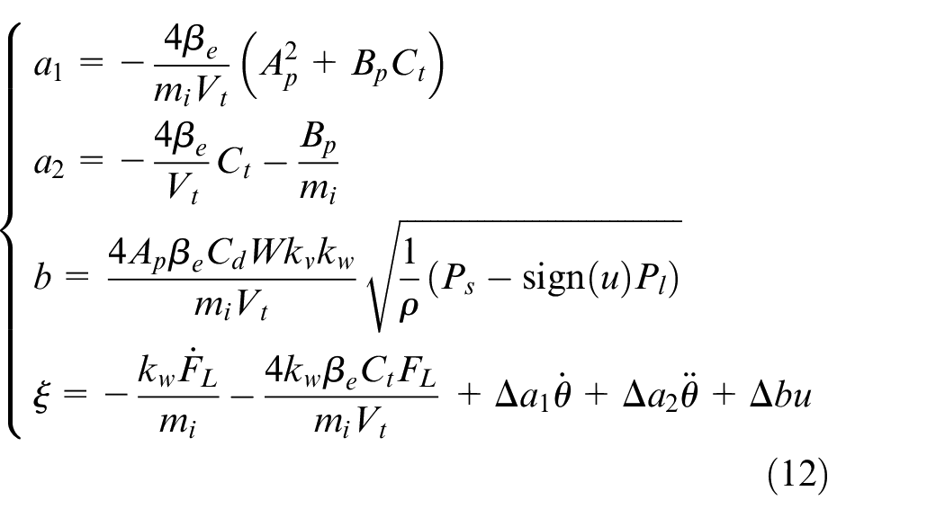
Given difficulties in obtaining the exact value of
Define the state variables
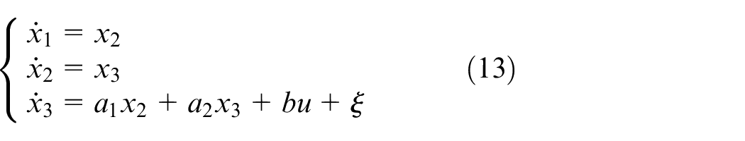
The useful and necessary lemma and assumption are shown as follows:

where
Control system design
This section presents a backstepping sliding mode controller based on hybrid extended state observer of the tillage depth control system. The design of controller and observer is carried out separately. The theoretical examination of the proposed observer and controller has shown uniformly bounded stability.
Observer design
During tillage operations, the plow exhibits an up-and-down oscillatory motion. In the depth control system, feedback on the lift arm’s angle value is solely accessible via a contact angle sensor. Additionally, it is important to acknowledge that during tillage processes, uncertainties such as intricate road surfaces, the tractor body’s oscillations, perturbations in modeling parameters, and so on, impinge upon the precision of tillage depth tracking. Thus, the necessity arises to design an observer that can estimate these unquantifiable variables.
Typically, an extended state observer is utilized to estimate the system’s state variables and disturbances. To the best of our knowledge, the HESO amalgamates the merits of both linear and nonlinear extended state observers. It is capable of accurately estimating minor disturbances while maintaining a high response speed and estimation precision during sharp changes in disturbances. Consequently, a HESO is designed to estimate the unmeasurable variables in the tillage depth control system.
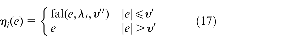
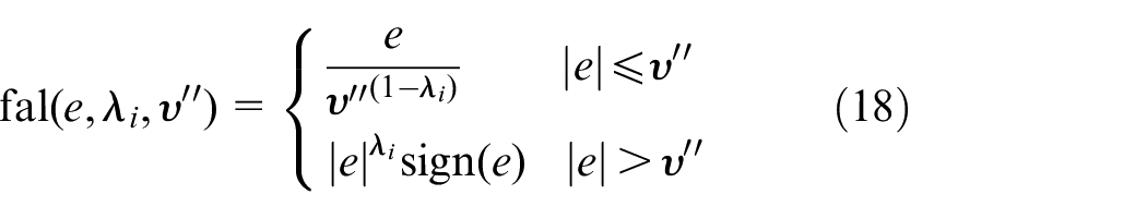
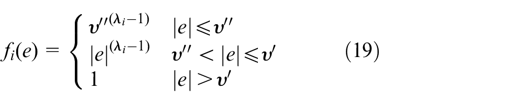
The lumped disturbance
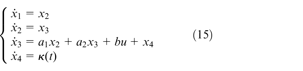
where
In the tillage depth control system, we can only obtain the value of the lift arm angle
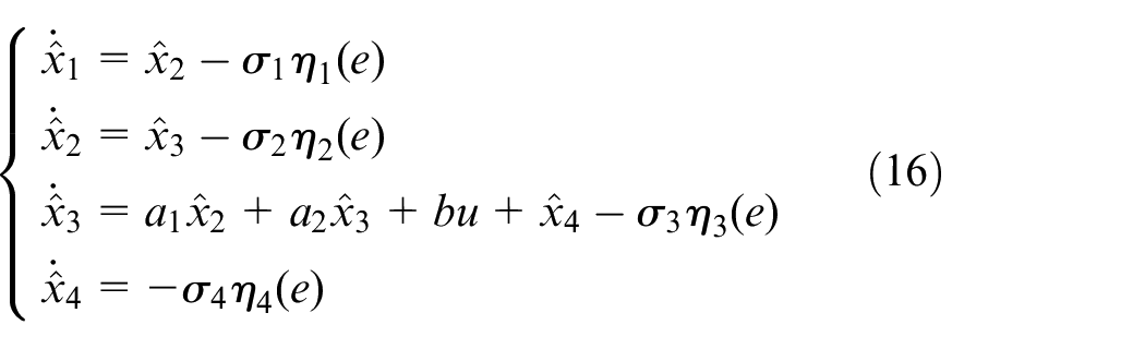
where
where
where
At the same time, selecting
where
Subtracting equation (21) to (15) yields
where

where

where
Then, we choose a positive-definite candidate Lyapunov function as:

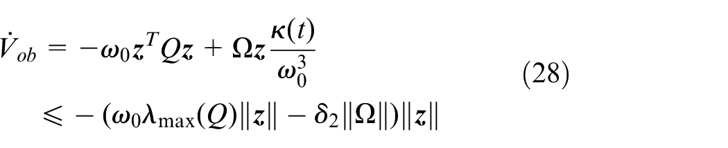
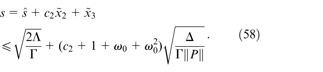
We can obtain that

where
From equations (23) and (24), we can obtain the derivatives of equation (25):
Define
where
According to equation (26), we have
The earlier equation, given above, can be rewritten as:
Evidently,
in a finite time. In addition, the estimation errors can be made arbitrarily small by adjusting the observer gain
Controller design
In this section, a backstepping based SMC design scheme is established for the tillage depth control system in equation (13) to make angle
The backstepping technique is composed of a step-by-step construction of a new system with states

Define a Lyapunov function as
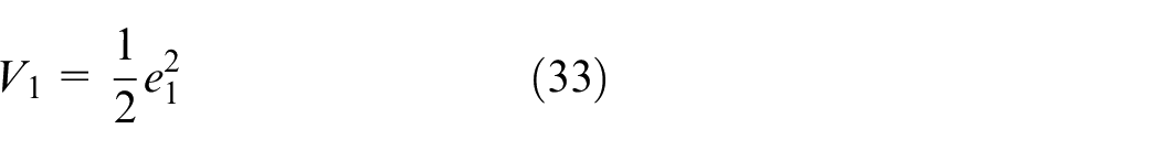
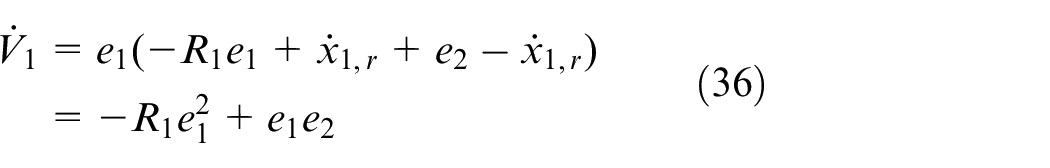
The derivation of


where
Define
Define a new Lyapunov function as
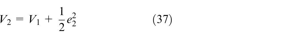
The derivation of
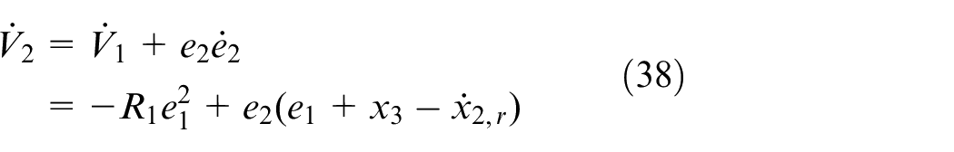
By equation (35), we have

Due to the fact that in practical applications, we can only obtain the estimation values of state variables, define


where


where
Note that

One has
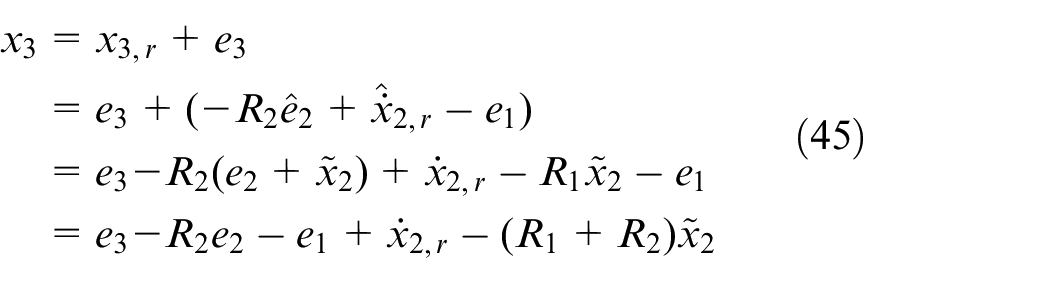
Submitting equation (45) to (38), yields

The sliding surface is chosen as

where
where
We define


where
The following fast power-reaching law is employed to realize the approach of the sliding mode variable

where
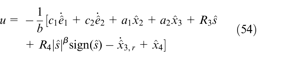
By combining equations (48) and (53), the sliding mode controller can be designed as
Stability analysis
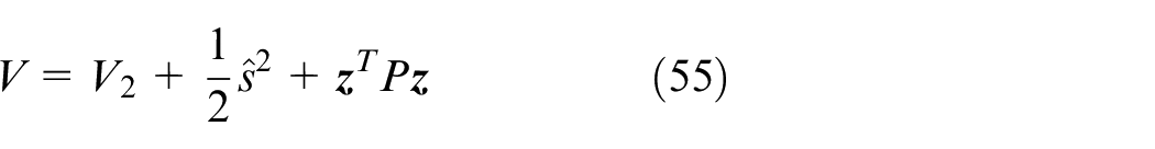
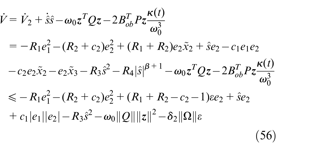
Using Young’s equation:
where
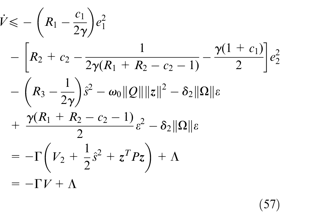
According to equation (57),
So the system (13) can be converged to the neighborhood around the sliding surface
Results and discussion
Simulation experiment
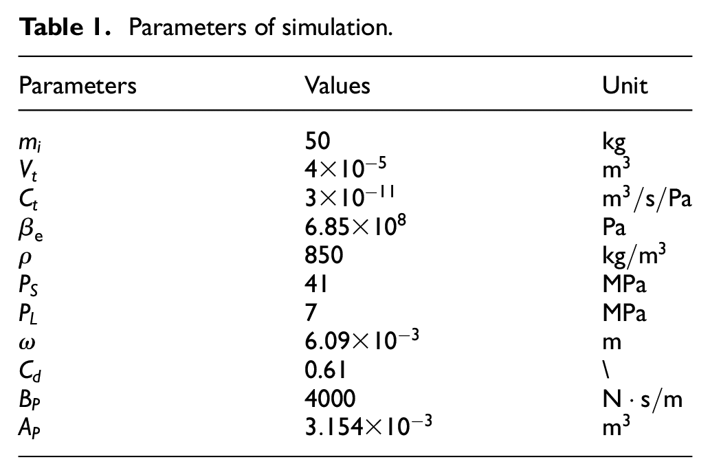
To validate the effectiveness of the proposed HESO-BacksteppingSMC control algorithm, we conducted simulations on the tillage depth control system using AMESim and Matlab/Simulink. AMESim is a scalable simulation platform for mechatronic systems launched by the French IMAGINE company. AMESim designs and provides a variety of software interfaces, which can be co-simulation analysis with Simulink. We build a hydraulic system model in AMESim. The displacement value of the valve core in AMESim are passed to Simulink to implement the control algorithm, and the calculated control input is passed to the electro-hydraulic servo valve in the AMESim model. The detailed system parameters are shown in Table 1.
Parameters of simulation.
Observer performance verification
Due to the complex and variable environment of tractor plowing operations, the tillage depth control system is subject to significant external time-varying disturbances, internal parameter perturbations, and unmeasured states, all of which directly affect the performance of the controller. In this section, we compare the HESO used in this study with traditional linear ESO and nonlinear ESO. The tillage depth control system was built in the Matlab/Simulink platform, and a virtual disturbance was applied as the system input:
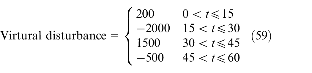
The observer parameters were set as
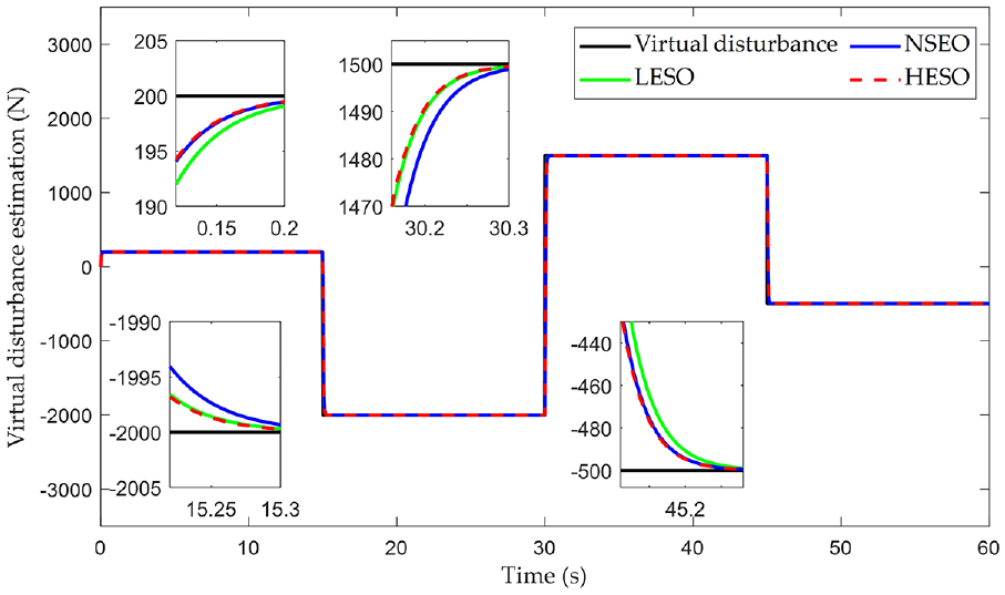
Observer performance comparison.
By comparing the estimated values of the three observers, it can be observed that when the given disturbance values are small at time 0 and 45 s, the nonlinear ESO performs better than the linear ESO in terms of observation. However, when the given disturbance values are large at 15 and 30 s, the linear ESO shows better observation performance. The hybrid ESO used in this study can switch between the linear ESO and nonlinear ESO, adapting to the complex and variable disturbance values in the tillage depth control system, and accurately estimating disturbances in a fast and precise manner, outperforming the traditional ESO.
Controller comparison and analysis
To test and verify the high-performance control effect of the control algorithm proposed in Section 3.2, the following controllers were set to track the same desired trajectory for tillage depth
(1) The proposed HESO-BacksteppingSMC controller. As mentioned in Section 4.1, the observer parameters are chosen to strike a balance between the controller’s response speed and steady-state accuracy. The parameters are set as follows:
(2) HESO based sliding mode controller (HESO-SMC). The observer parameters are the same as those used in this study. The sliding surface is set as
(3) Fuzzy-PID controller without state observer in [16]. With the tracking error signal
Figure 4 shows the interface of the Co-simulation system built with AMESim and Matlab/Simulink. A nonlinear and time-varying disturbance force
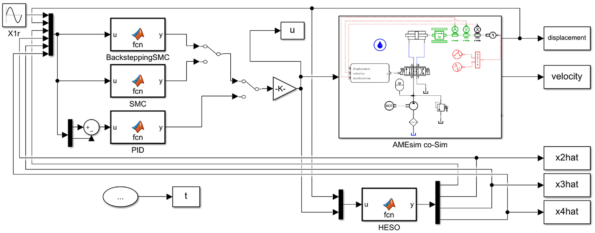
Co-simulation system interface.
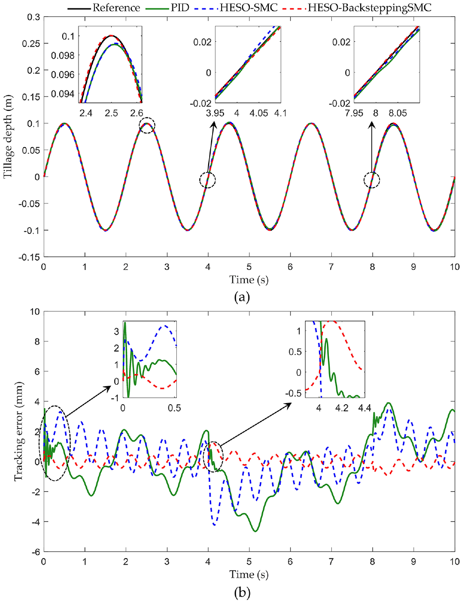
Comparison of the tillage depth tracking results: (a) tracking trajectory and (b) tracking error.
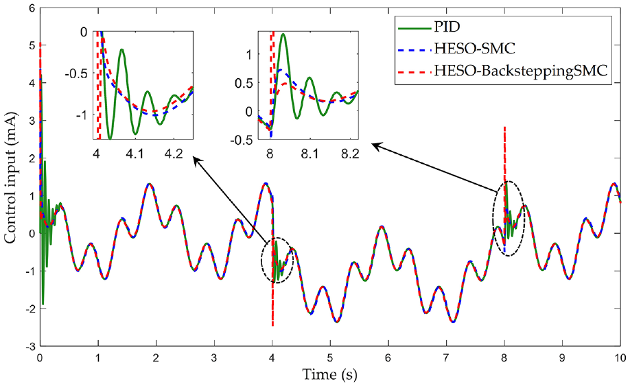
Control input.
From the recorded tillage depth tracking trajectory and error in Figure 5, it can be clearly seen that the proposed algorithm is able to quickly track the reference trajectory and maintain the tracking error within a desired range of
An in-depth analysis of the proposed algorithm is facilitated by additional simulation results depicted in Figure 7. Figure 7(a) and (b) represent the observer’s estimated values and the estimation error for velocity, respectively. The authentic velocity value is sampled at a frequency of 100 Hz, utilizing the inherent velocity sensor in AMESim. Notably, the velocity estimation error appears to be minimally influenced by abrupt step disturbances occurring at the 4th and 8th seconds. In Figure 7(c), the two curves plotted against the left y-axis correspond to the estimated values of the total disturbance, both with and without the presence of a load applied disturbance. The curve aligned with the right y-axis represents the applied disturbance itself. Observations reveal that prior to the application of the disturbance, the uncertainties induced disturbances in the model parameters are accurately estimated. It is noteworthy that according to equation (7), the applied disturbance does not merely accumulate with the total disturbance but merges in a second-order nonlinear format with other disturbances. These simulation results substantiate the observer’s proficiency in effectively estimating the total disturbance, even when the applied disturbance undergoes changes.
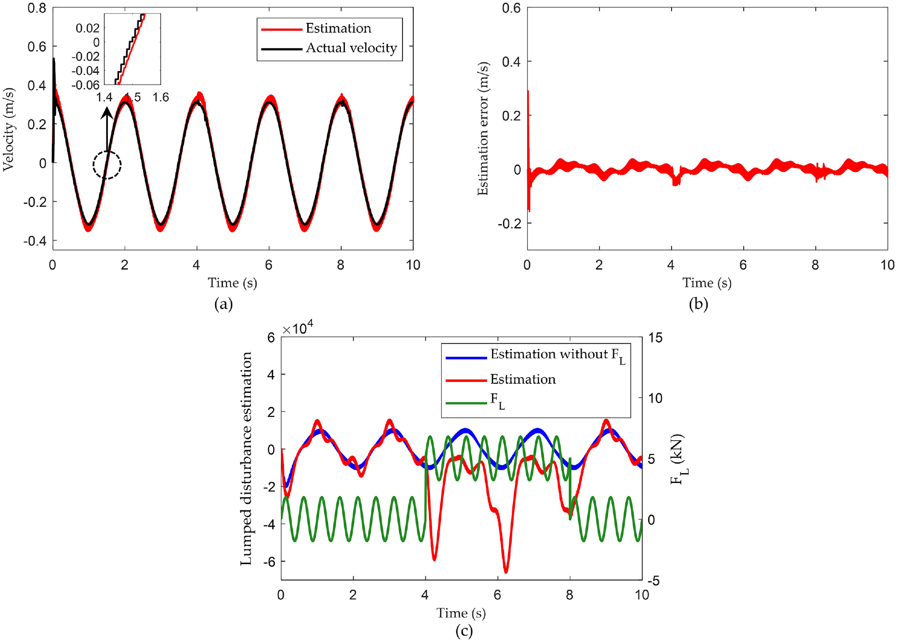
Additional simulation results: (a) velocity and its estimated value, (b) velocity estimation error, and (c) estimation of the total disturbance.
In Figure 8, the tracking performance of the three control algorithms is quantitatively evaluated. Box plots of the tracking errors for each algorithm are shown, along with bar charts depicting the maximum absolute error, average absolute error, and standard deviation of the absolute error. The proposed HESO-BacksteppingSMC controller achieves a maximum absolute error of 1.2 mm, significantly lower than the HESO-SMC controller (4.2 mm) and PID controller (4.7 mm). In terms of the average absolute error, the proposed algorithm reduces the error by 75.5% and 79.6% compared to the two comparative algorithms, respectively. Moreover, the standard deviation of the absolute error is reduced by 77.2% and 81.1%, respectively. This analysis demonstrates that the proposed algorithm outperforms the other algorithms in terms of both the average level and dispersion of tracking errors when following the desired tillage depth trajectory. Despite the disturbances from the sinusoidal and step inputs, the proposed algorithm maintains good tracking performance, highlighting its high robustness.
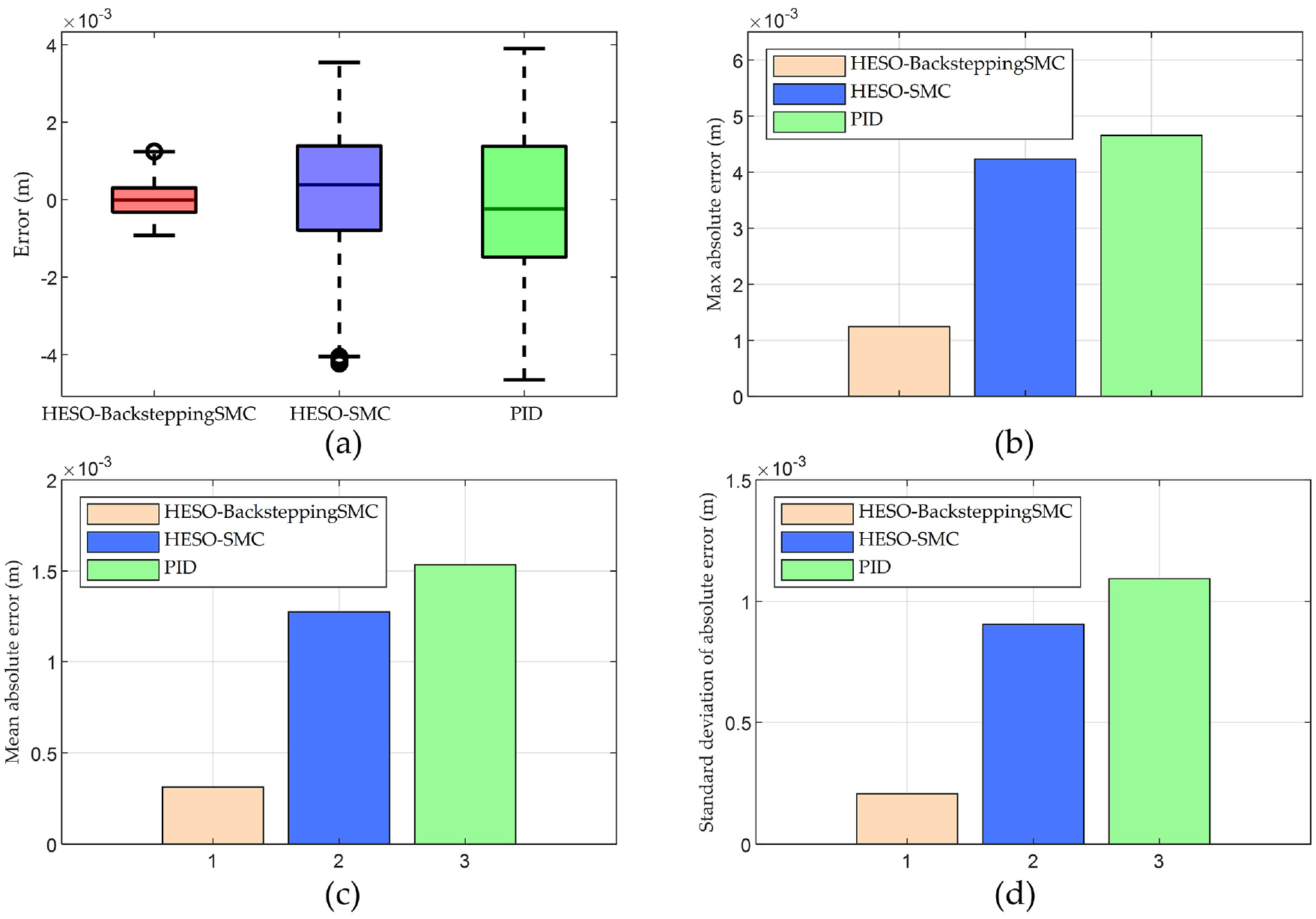
The error data analysis: (a) box plots, (b) maximum absolute error, (c) average absolute error, and (d) standard deviation of the absolute error.
Field operation experiment
The control system for tillage depth was implemented on a modified Dongfanghong LX954-C wheeled tractor, which was retrofitted with an electronic control mechanism. The goal of this study was to detect and modulate the operational depth of a moldboard plow. An STM32 embedded system served as the processing unit for this endeavor.
Experimental calibration of measurement model parameters
The accuracy of the IMU measurements pertaining to the hitch-plow pitch angle in dynamic states was found to be sub-optimal. To address this, a data-fitting method was adopted for the calibration of the relative correlation between the lift arm angle and the hitch-plow pitch angle under static states. As demonstrated in Figure 9, the tractor equipped with the suspended plow was stationed on a slanted platform. The suspension point was periodically adjusted. For each calibration point, data corresponding to the lift arm angle and the hitch-plow pitch angle were documented. Using a higher-level computational software, a mathematical model was fitted to these points. The outcomes of this fitting process are illustrated in Figure 10.
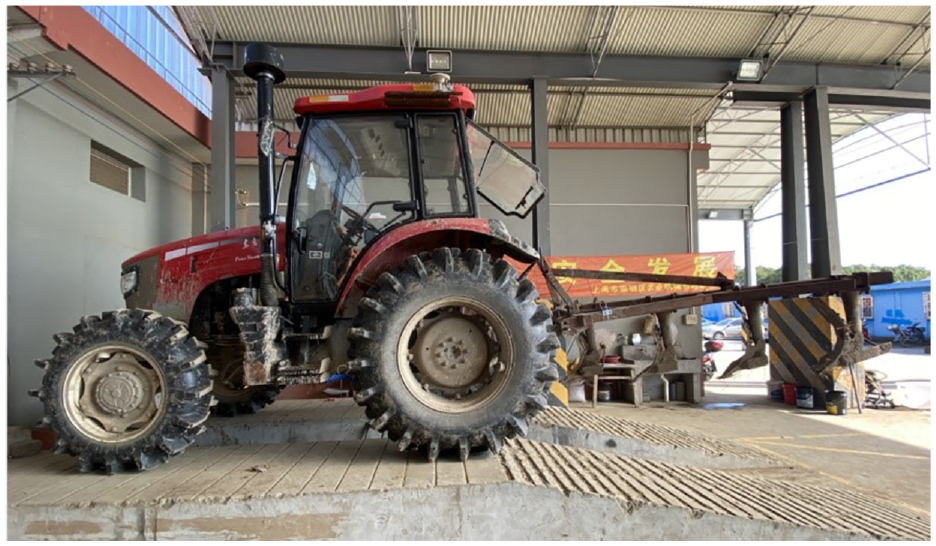
Angle fitting test.
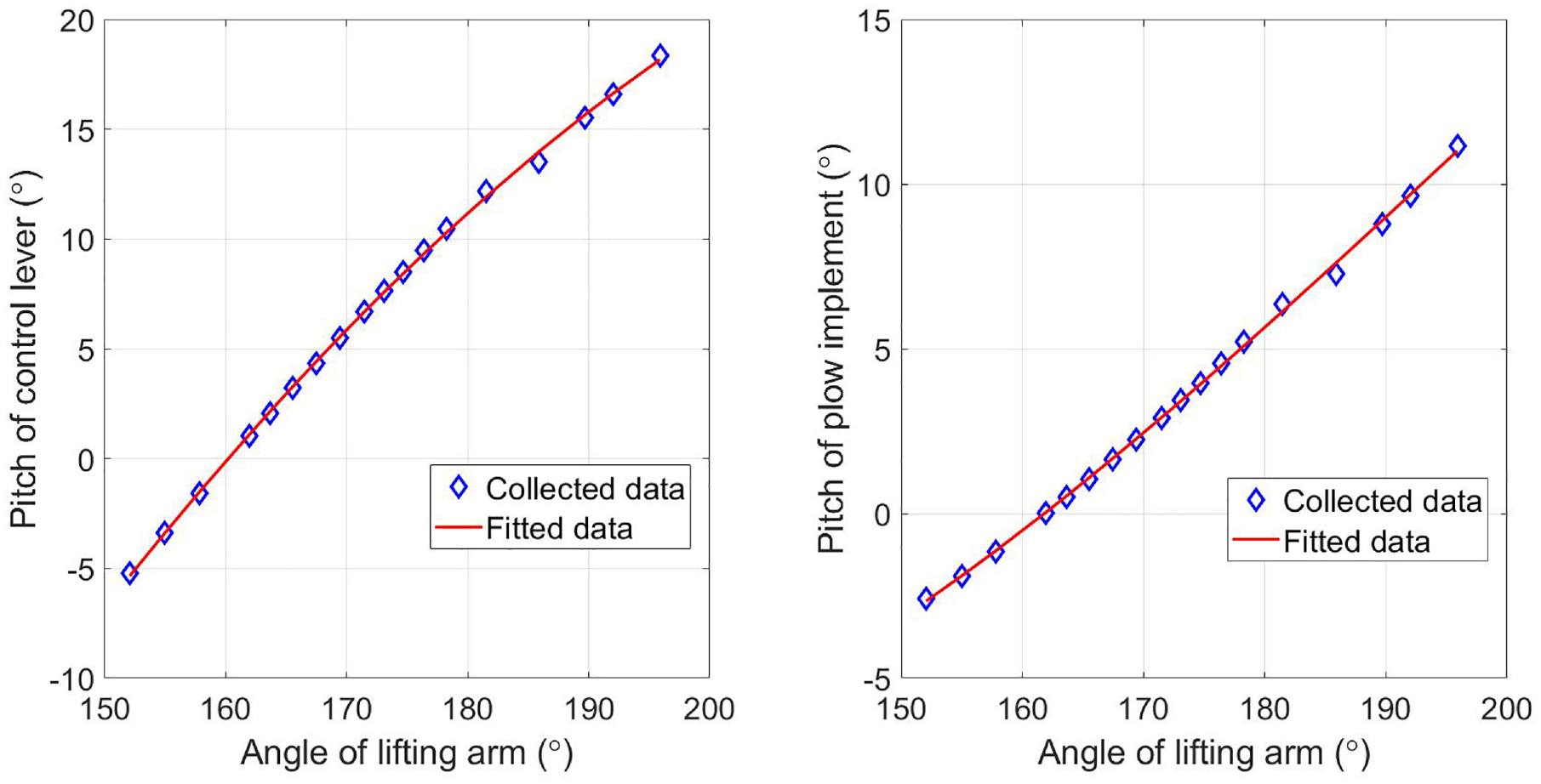
Curve fitting results for angles.
The calibration model for fitting the drawbar pitch angle with the lifting arm angle is:

where
The calibration model for fitting the plow pitch angle with the lifting arm angle is:

where
When the plow is on a flat ground, the drawbar pitch angle and the plow pitch angle are 0.96° and 0.11°, respectively. Combining equations (4), (60), and (61), the relationship model between tillage depth and lifting arm angle is:

Field tillage experiment
To test the feasibility and accuracy of the modified tractor tillage depth measurement and control system, and further validate the superiority of the designed tillage depth control algorithm, actual plowing experiments were conducted in the field. The tractor and moldboard plow used in the test are shown in Figure 11. Meanwhile, as shown in the test scene graph in Figure 11, the hardware design scheme of the tillage depth regulation unit is given.
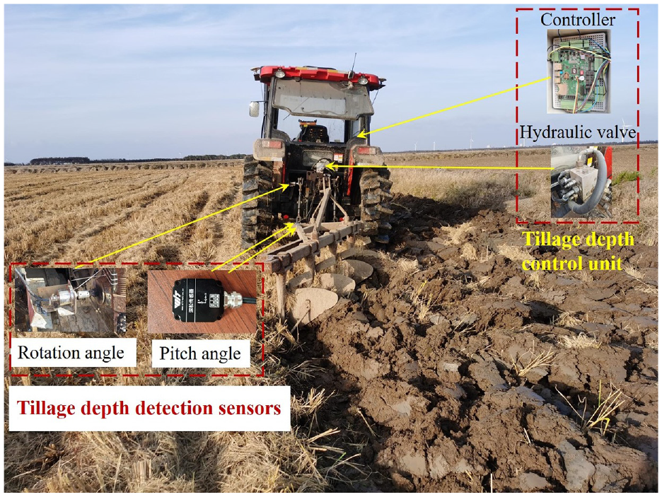
Field experiment scene.
The experimental study was carried out at a field situated in Shangshi Farm, within the Chongming District of Shanghai. This field had already undergone harvest, but not subsequent tillage. A tractor driver navigated the vehicle in a straight line, maintaining a fixed gear and throttle setting. The predetermined target for the tillage depth was established at 20 cm. The experiment was designed to compare the three tillage depth control algorithms as detailed in section 4.1.2. A STM32 controller was employed to transmit real-time tillage depth data to a computer through serial communication, facilitating precise data logging.
Firstly, performance testing of the automatic measurement system for tillage depth was carried out. Actual tillage depth have been measured manually every 2 m along the direction of the tractor. And the The speed and position of the tractor at a certain moment were recorded by the GPS system, so we can correspond the tillage depth value measured by the ruler with the system’s automatic measurement value one by one. Details are shown in Figure 12. Actual tillage depth have been measured manually every 2 meters along the direction of the tractor. And the manually measured tillage depth are compared with that of automatic measurement to verify the performance of the tillage depth automatic measurement system. Figure 13 shows the comparison results of discrete data between automatic measurement of tillage depth and manual measurement of tillage depth. The Root-mean-square deviation of the two tillage depth measurement methods is 0.46 cm. From Figure 13 and the error statistics results, it can be seen that the automatic measurement method can effectively ensure the accuracy of tillage depth measurement, and the measurement frequency is more efficient and higher.
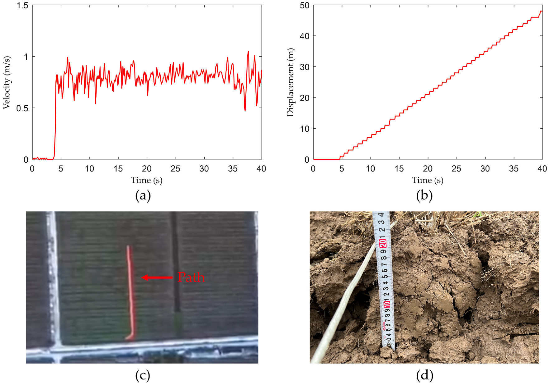
The error data analysis: (a) tractor velocity, (b) tractor displacement, (c) plowing operation path, and (d) measurement value of tillage depth with a ruler.
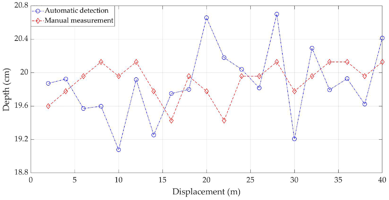
Comparison of tillage depth measurement results.
Secondly, performance testing of the tillage depth control system was carried out. Utilizing Matlab software, the actual tillage depth curve and tillage depth error curve were graphically represented, as depicted in Figures 14 and 15, respectively.
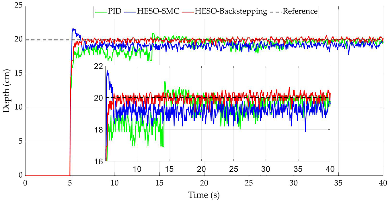
Variation curve of tillage depth.
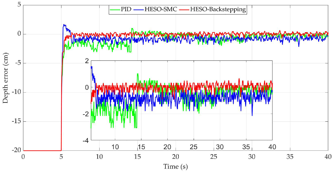
Variation curve of tillage depth error.
Starting from the 6th second when the tillage depth value of the algorithm in this paper reaches steady state, the absolute values’ comparison of tillage depth error of the three algorithms is given in Figure 16.
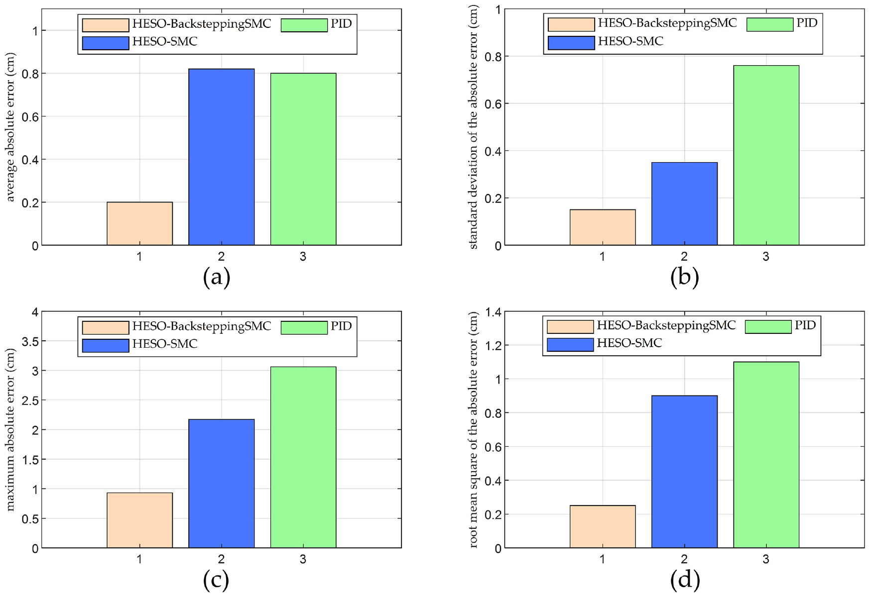
Analysis of experimental results: (a) average absolute error, (b) standard deviation of the absolute error, (c) maximum absolute error, and (d) root mean square of the absolute error.
Based on the data presented in Figures 14 to 16, it is clear that the developed tillage depth control system in this study offers effective control over the tillage depth of a tractor. The proposed HESO-BacksteppingSMC controller demonstrates superior performance in terms of the swiftest response speed, the highest steady-state accuracy, and an overall smooth variation curve for the tillage depth. Upon achieving steady-state, the mean absolute value of the tillage depth error is recorded at a negligible 0.20 cm. Further statistical analysis reveals a standard deviation of 0.15 cm and a maximum value of 0.93 cm. The control performance of the proposed system is markedly superior when compared to the performance of the HESO-SMC controller and the PID controller. This results in a significant improvement in the overall quality of the plowing operation.
Conclusion
In light of the challenges presented by equipment vibrations and sensor limitations during tractor tillage operations, we have developed a refined, accurate approach for static tillage depth measurement. This innovative method integrates the measurement of the lower link inclination angle with the implement inclination angle. Utilizing a mechanical angle sensor, the lift arm angle is measured and then associated with the lower link and implement inclination angles to derive a relational model between the lift arm angle and tillage depth. This technique effectively harnesses the accuracy of the static model from the inclination-based measurement method and the dynamic stability enabled by the mechanical assessment of the lift arm angle. Acknowledging the uncertainties introduced during the complex real-world plowing activities, a hybrid extended state observer is formulated to estimate the model’s discrepancies, encompassing external disturbances and the velocity and acceleration data typically unattainable with high precision through conventional sensors. Distinct from classical ESOs, this enhanced hybrid variant can adjust observation strategies contingent on a predetermined error threshold. Further, by integrating the backstepping controller with the sliding mode algorithm, a backstepping sliding mode controller is conceived. The application of a fast power-reaching law is instrumental in alleviating chattering, and according to the Lyapunov stability analysis, both observation and control errors are uniformly and ultimately bounded. This assertion is corroborated by comparative analyses stemming from simulations and actual field exercises, underscoring the effectiveness of the proposed tillage depth control system.
During plowing, the tractor’s engine load bears significant influence on both farming quality and fuel consumption. Consequently, the creation of an efficient draft-position mixed control method constitutes a focal point of our forthcoming research endeavors. Moreover, we recognized that the technique of employing a ruler for sampling and measuring the actual tillage depth during field experiments lacks sufficient accuracy. Addressing this, the formulation of an enhanced method to augment precision is slated for future exploration and development.
Footnotes
Declaration of conflicting interests
The author(s) declared no potential conflicts of interest with respect to the research, authorship, and/or publication of this article.
Funding
The author(s) disclosed receipt of the following financial support for the research, authorship, and/or publication of this article: This research was funded by the National Key Research and Development Program (Grant 2022ZD0115804), the Key Research and Development Program of Jiangsu Province (BE2021313), and the Agricultural Independent Innovation Fund of Jiangsu Province (CX(22)2040).