
Abstract
The article describes the process of development of an essentially new wheel suitable both for moving on flat ground and for travelling on stairs. The stair-climbing wheel is composed of rotary circular segments arranged around a shared carrier with arms to form a complete circular profile of the wheel adapted for moving on flat ground; for travelling on stairs, individual segments are rotated by an appropriate angle to touch down tangentially on the stepping surface of the stairs. The dimensions of individual segments, the centre of rotation of individual segments and the angle of their partial turn have been chosen so that the length of the arc along which the circular segment rolls is equal to the length of the stepping surface of an average stair, and, at the same time, the circular segment touches down tangentially on the stepping surface while the wheel turns around the edge of the previous segment. Using the rotation angle of the turnable segments, the wheel can be adapted to the height of non-standard stairs. The segments can be inclined in both directions for bidirectional movement of the wheel up and down the stairs. An undercarriage equipped with these wheels can be used in the field of exploratory robots and for the transportation of persons and materials on stairs.
Introduction
The development of a wheel that would be able, besides moving on flat ground, to travel on stairs or to run up a curb has a long history in the field of engineering, and thousands of different technical solutions have been patented. The development of a wheel providing the advantages of smooth movement on flat surfaces at a relatively high speed and with low energy demands along with the possibility of safe and relatively smooth travelling on stairs and problem-free running up the first stair has continued, as documented by the relatively recent solution patented in 2011 (see Figure 1). The wheel is fitted with small turnable protrusions that can be reclined inside the wheel.

The US patent US 20110127732 of the stair-climbing wheel. 1
Current technical solutions of a wheel adapted for travelling on stairs can be categorized into six major groups: Belt undercarriages or combined belt undercarriages with sliding wheels, auxiliary belts for running up the first stair and a lifting mechanism as appropriate – also belts with the configurable circumference’s shape belong to this group. Wheel undercarriages with large wheels, alternatively completed with a lifting mechanism. Multiple-arm wheels with two, three (Weinstein wheel, tri-star concept) and four arms, equipped with smaller driven wheels at the ends. Hybrid walking systems: mechanical legs combined with wheels for moving on the ground. Polymorphous wheels whose shape changes from a circular profile for moving on the ground to a shape matching the stair. Special profiles of solid wheels: The wheel is equipped with a varied number of protrusions (usually three or four) with a cycloid-shaped, logarithmic or Archimedean spiral profile. The solid protrusions are used for moving on stairs; when moving on flat ground, the protrusions are covered with circular segments, or, alternatively, auxiliary wheels are slid out.
The widest range of applications for travelling on stairs and over obstacles was achieved by a group of solutions based on reconfigurable belt undercarriages. 2 A very interesting principle with reconfigurable belt’s outer circumference between wheel and track was introduced in Xueshan et al. 3 Some of these belt undercarriages are completed with auxiliary mechanisms to raise the undercarriage up to the first stair. To this group belong also the undercarriages with belts on swinging arms. 4,5 Higher energy demands of the tracks while moving both on flat ground and on stairs, problems with shear control of movement direction and problems due to small objects getting wedged between the belt and the wheels are the disadvantages of the belt undercarriages. The aforementioned technical solutions attempt to remove the disadvantages of belt undercarriages using sliding wheels for moving on the ground, for example, as indicated by the patented solution illustrated in Figure 2. 6
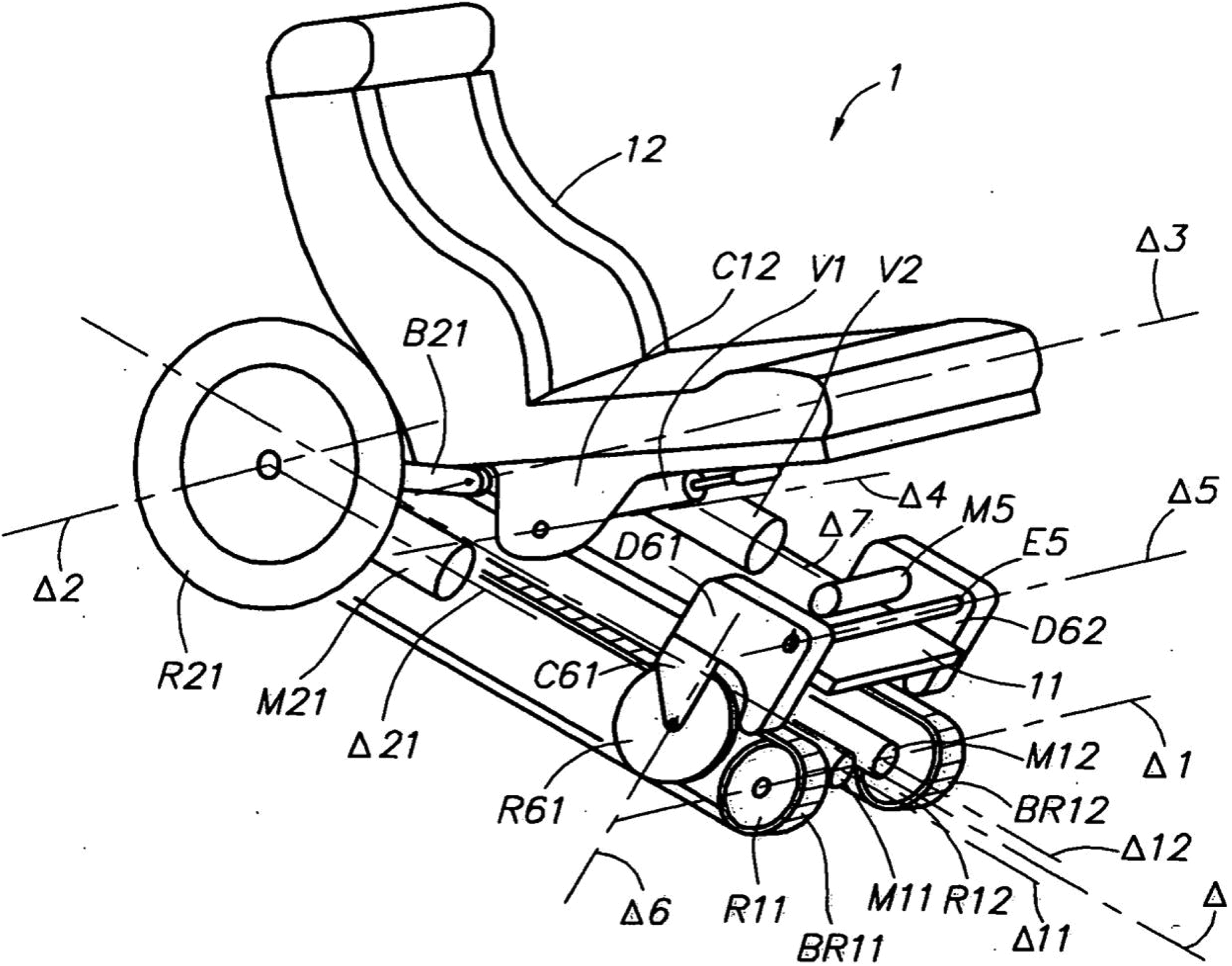
The WIPO patent WO2004108045 with a crawler and wheels. 6
Wheel undercarriages are usually designed either with wheels sufficiently large to be able to overcome the stair height, such as the mobile robot Orpheus, 7 or to utilize a solution known as the rocker-bogie mechanism 8 ; alternatively they are equipped with various auxiliary mechanisms for lifting the wheel up to the stair, for example the solution described in the patent of Carstens 9 and the solution of the lifting mechanism with an eccentric paddle mechanism that was introduced in Sun et al. 10 A wheelchair with manual lever propulsion of the lifting mechanism was introduced in Sasaki et al. 11 The solution with a group of two or more driven wheels placed on a turnable carrier has become more widespread. When moving on the flat ground, only the driven wheels turn while the carrier only copies the terrain; when moving on stairs, the wheels are braked and the carrier turns with the wheels in a manner so that the profile of the stairs falls between individual wheels of the carrier. A number of solutions exist for this design; for example, two wheels on a turnable arm are used by the robotic wheelchair 12 ; the principle of the two wheels on the flipped carrier is also used for stairclimbing in Wang et al. 13 ; a variant of the known Segway principle with pairs of wheels on each side is used by the powered wheelchair iBot. 14 Three wheels on a carrier have been known as the wheel cluster, Weinstein-wheel or tri-star wheel concept; the Loper robot undercarriage 15 can be mentioned as an example. The four wheels on a shared carrier are also the subject of a patented solution. 16 A solution introduced in Sugahara et al. 17 with transformable wheeled four-bar linkages belongs partially to the next group with wheels combined with legs.
The robot leg-wheel ASTERISK H 18 with wheels at the ends of the legs is a representative of a group of solutions utilizing a hybrid combination of legs and wheels. An interesting solution is provided by the hybrid platform Quattroped; this platform transforms two semicircular wheel parts into a leg. 19 Another hybrid solution with lifting mechanism and wheels on some kind of mechanical legs was introduced in Chocoteco et al. 20 Although technical solutions utilizing polymorphous and deformable wheels 21 are used, these usually find applications only as research projects. The last group of principles is based on wheels with solid protrusions; although such wheels are able to move on stairs and over obstacles, their movement on flat ground is too ‘bumpy’. The best results for the movement on stairs are shown by wheels with protrusions shaped as a logarithmic spiral 5, as illustrated in Figure 3, where the centre of wheel 1, while rolling over the stepping surface 4 of the stair, moves at least partially along a line 6 in the stairs’ rising direction, and therefore the movement is very smooth. 22 Protrusion 2 can be covered using auxiliary circular segment 7 for moving on the flat ground, as shown in Figure 3 on the right.

Logarithmic spiral wheel for the stair-climbing vehicle.
The wheel with rigid protrusions is also introduced in the contribution of Castillo et al. 23 and solution of a wheel with flexible protrusions can be mentioned as an example in Eich et al. 24 Interesting solution of the ‘bumping’ problem, introduced in Pan et al., 25 is a foldable wheel that consists of two incomplete wheels on arms; these two wheels form protrusions necessary for moving on stairs and can be folded up into one circular wheel to move on the flat surface. The hybrid platform Quattroped, mentioned above in Chen et al., 19 belongs also to this group of the foldable wheels. The transformation mechanism of this wheel combines two half-circles as a leg with the two degrees of freedom in case of stair-climbing and it can combine these half-circles also as a circular wheel. The well-done comparison of various stair-climbing principles including their stability analysis is carried out in Tao et al. 26
Synthesis of a wheel with circular turnable segments
The new solution seeks to remove the disadvantages of existing solutions, particularly the structural complexities and energy demands, in short, to adapt a simple wheel for smooth movement also on stairs. Clearly, these are quite opposite requirements for the wheel mechanism. The wheel should have a full and perfect circular shape for travelling on flat ground, and at the same time a shape with rounded protrusions, showing the logarithmic spiral profile at best, or a circular profile on both sides of the projection. In addition, there is a requirement for relative simplicity of the wheel mechanism, which is at variance with the requirement for integrating both of the main functions – travelling on flat ground and travelling on stairs – in a single mechanism.
Conceptual design
Such opposing technical requirements can be approached using TRIZ (the Russian acronym for the Theory of Inventive Problem Solving) methodology and its tools for solving technical contradictions: heuristic principles
27
built based on an analysis of a large quantity of patented technical solutions in various fields, and summarized in the so-called Altshuller’s table. Altshuller’s table can be used to formulate and overcome technical contradictions based on problem categorization in 39 categories that should be resolved; for example, the shape of the wheel should be circular as well as having protrusions; complexity of the device leads to larger dimensions; and complexity of the device increases energy losses. In order to solve such contradictions, the table offers 40 innovative principles for resolving any given technical contradiction. The following principles follow from recommendations based on Altshuller’s table: Principle 1 – segmentation, that is, the division of the circle of the wheel to the individual segments. Principle 5 – merging, that is, merging areas used for rolling on flat ground and rolling up the stepping surfaces of the stairs in a single body. Principle 6 – universality, that is, the use of the same objects for rolling on flat ground as well as for rolling on the stepping surfaces of the stairs.
Based on these recommendations, the circle was divided into segments installed as turnable segments on the arms of the carrier; when travelling on stairs, these segments would allow reconfiguration to obtain a shape approaching the requirement for the wheel rolling on solid protrusions (see Figure 4 on the left); for movement on flat ground, the circular segments form a perfect and full circle (see Figure 4 on the right).

Basic principle of segmented wheel. 1 – carrier; 2 – arms; 3 – segments.
However, identification of the basic principle of the solution for a wheel travelling on stairs – segmentation of the circular shape in multiple turnable circular segments – is only the beginning of the technical solution. The purpose is to find such a kinematic structure of the wheel that will enable the circular segment to touch down tangentially on the stepping surface of a standard stair while the wheel turns around the edge of the previous segment. Dimensions of individual segments, the centre of rotation of individual segments and the angle of their partial turn must be such that the length of the arc along which the circular segment rolls is equal to the length of the stepping surface of an average stair. The wheel can be adapted to the height of the stairs using the angle of partial turn of the turnable segments. This technical solution of the wheel provides advantages both for movement on flat ground where the wheel exhibits an ideal circular shape, disturbed only by possible transitions between the segments, and for travelling on stairs where a suitable choice of the segment’s angle provides motion with only a little swaying. The segment’s turn angle can be controlled using a suitable control algorithm based on the measurement of the stair dimensions using sensors. In terms of smoothness of the movement on stairs, it would be better if the contact area of the turned segments on which the wheel rolls on the stairs could have the shape of a logarithmic spiral, which is advantageous for the movement of the wheel centre along a line parallel to the staircase inclination, but the circular shape also provides a very smooth movement along stairs with a deviation of the wheel centre position from the line of the order of millimetres. The issue of synthesis of such a wheel gives rise to the following basic unknowns: number of turnable segments; position of the segment rotation axis – symmetric or asymmetric; suitable distance of the segment rotation axis from the wheel centre; the range of diameters of the wheel for the given number of segments; optimal diameter of the wheel for the smallest sway amplitude while travelling on stairs; implementation of the inner mechanism for partial rotation of the segments and the related number of drives.
Geometric analysis of the wheel mechanism
An ideal number of circular turnable segments will follow from the geometric analysis of mutual positions of the partially turned segments towards the standard stair. The standard dimensions of the stair are a riser height of 170 mm and tread width of 290 mm according to the so-called average stair according to the Czech national standard ČSN 73 4130 ‘Staircases and Inclined Ramps’, which specifies the design of staircases and inclined ramps as footpaths. Considering that the ideal number of segments is unknown at this moment, the kinematic structure of the wheel with three circular segments is used for the derivation (see Figure 5).
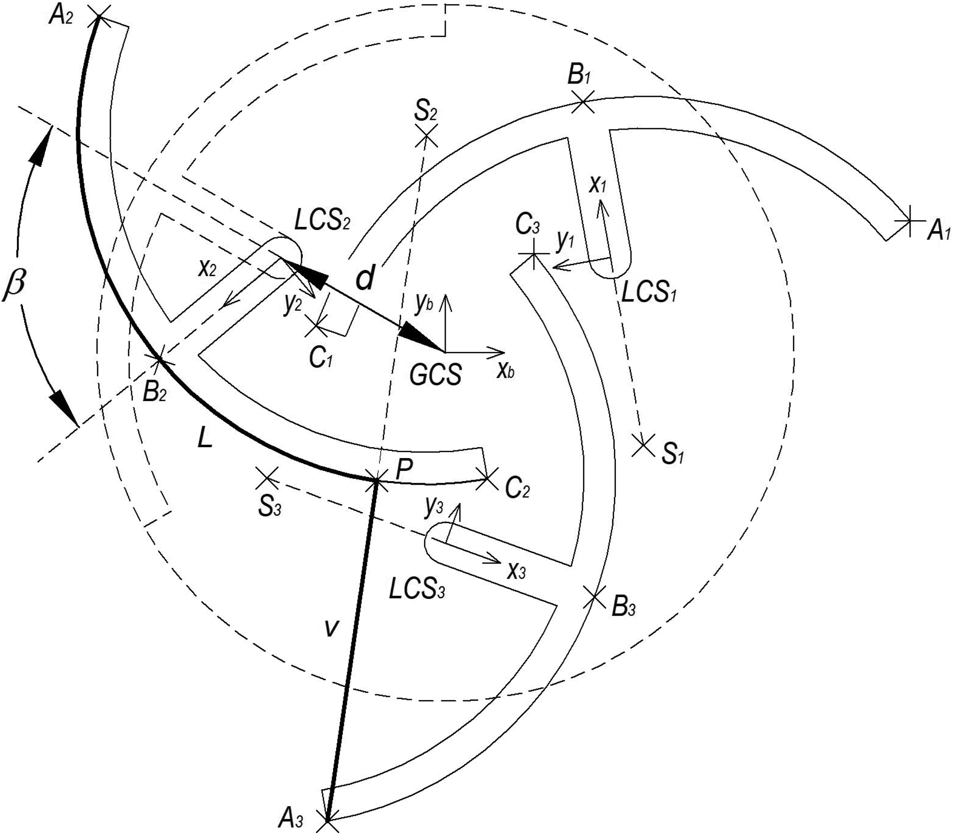
Calculation scheme of the geometric analysis.
The purpose of the analysis of the geometric conditions is to calculate the distance v that must correspond to the stair height of 170 mm and to calculate the length of the rolling curve L that must correspond to the stepping length of the stair of 290 mm for two variable parameters of the segment: distance d of the segment rotation axis from the wheel centre and the partial turn angle of the segment β. The number of segments is defined by the variable s. The control circle of the segment is defined by the points A, B and C of each segment. Segments 2 and 3 according to Figure 5 are used to calculate the height v and the length of the rolling curve L. Transformation matrices between the global coordinate system GCS and local coordinate systems LCS
2 and LCS3 of segments 2 and 3 are used to calculate the positions of the points

where the goniometric function sin(S) and cos(S) are abbreviated as s(S) and c(S), respectively, to shorten the expression. The angle variable S is the angle of rotation of the local coordinate system LCS2 against the global coordinate system GCS at β = 0 (all segments form circular wheel), so S can be expressed as

where s is number of segments, here s = 3. Angle β is the angle of rotation of the segment, d is distance between the segment rotation axis and the centre of the wheel and wheel radius is r. The homogeneous transformation matrix

The homogeneous coordinates of the points A2, B2 and C2 of the segment 2, as well as the coordinates of the points A3, B3 and C3 of the segment 3, expressed in their local coordinate systems LCS2 and LCS3 are fixed; they are indexed as A22, B22 and C22 and A33, B33 and C33, respectively, and can be expressed as
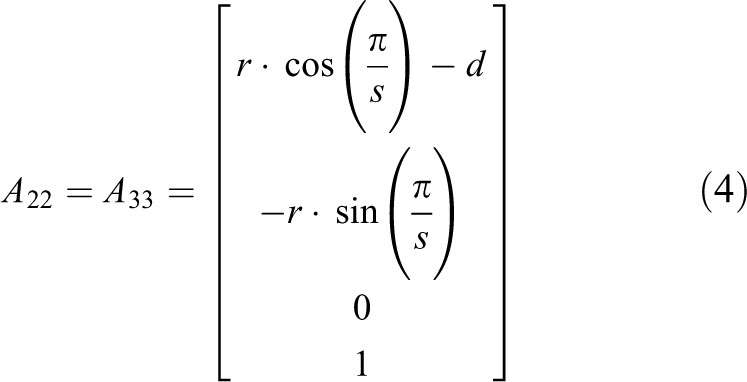
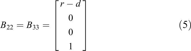
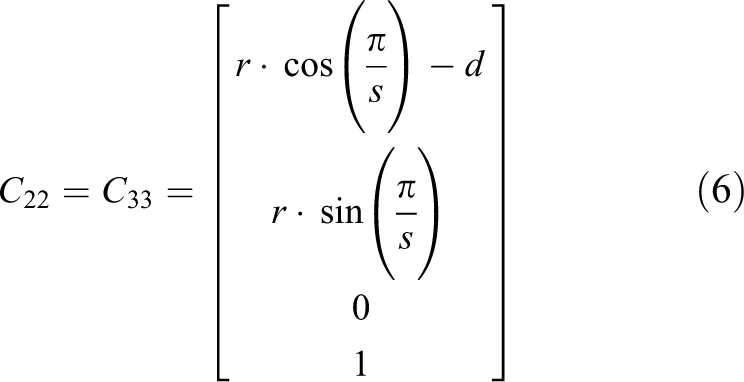
where r is the radius of the wheel. Segments 2 and 3 will be used to calculate the distance v and the length of the arc L for various numbers of segments, as illustrated in Figure 5. Then the following equations can be applied to the homogeneous coordinates of the points of segments 2 and 3 expressed in the reference coordinate system GCS.


Based on the calculations of positions of the points A2, B2 and C2 of the second segment in global coordinate system, the position of the centre S2 of the arc of this segment is calculated, as well as the position of the intersection point P of the line between the points A3, S2 and the circle given by the points A2, B2 and C2. Finally the length L of the arc between the points A2, B2 and P is calculated based on expression of the angle between the vectors
However, the task of the wheel dimensions synthesis, finding the radius r, a suitable distance d of the segment’s turning centre from the wheel axis and a suitable angle (β) of the segment’s rotation is an inverse task. We know the normalized height of the stair riser v = 170 mm and the normalized stepping length (tread width) L = 290 mm, and we need to obtain the range of possible wheel dimensions D = 2r, for which there is at least one solution for the pair of d and β that satisfies the given condition, and moreover, does so for various numbers of segments s. An attempt at designing an analytical solution and at creating inverse functions of individual relationships would lead to expressions that are too large and difficult to solve. Given that this is a typical optimization task, an iterative heuristic optimization method was used to solve this task, programmed in Matlab; for the chosen number of segments s and for the chosen wheel diameter D = 2r, this method seeks all combinations of the pair of the d and β parameter values in the chosen intervals of

was conveniently created as a quadratic functional of the deviations of v and L from the desired values, for which the method converges to a solution very well and rapidly. At first, we tried to obtain a solution of the wheel with three segments, that is, for s = 3. Based on the iteration optimization calculation, it was found that for the given wheel diameter D = 2r, there is always a single pair of the d and β values that satisfies the required stair height v and the length of the stepping surface L with the preset accuracy, while the value of 1 mm was set as satisfactory accuracy. The range of the wheel diameter D values, for which the error of setting the height v and the length L is within the given range, lies in the interval

Range of possible solutions of a three-segment wheel.
In order to find an optimal value of the wheel diameter D based on the values of the distance d of the segment rotation axis and of the segment inclination angle β, it is apparent that values in the left part of the graph are more advantageous, as the partial turn angle of individual segments is relatively small in this part of the graph, which is convenient especially for the use of pull rods to incline the segments. However, marginal values such as the wheel diameter D = 303 mm cannot be used either, given that the distance of the segment rotation axis from the wheel axis is d = 151.5 mm, and the segment rotation axis is thus found on the outer profile of the segment, providing no space for the placement of the relatively robust rotation joint. Practical values of the wheel diameter start from the value of D = 307 mm. Higher values of the wheel diameter cannot be used, either, for construction reasons. The partial turn angle of the segments is too large for these values, which complicates the inner mechanism for partial rotation of the segments. The range of up to β = 90° was preliminarily determined as applicable. Figure 6 illustrates a practical range of values of d and β, delimited by vertical lines, falling in the range of

Range of possible solutions for a wheel with four segments.
We also succeeded in finding a solution for a two-segment wheel for travelling on stairs; the calculation determined suitable values of d and β, as illustrated in Figure 8 on the left. Although segment inclination of the wheel is not feasible due to an intersection of the segments with the stair, a solution of the inner mechanism with a parallelogram is possible, as illustrated in Figure 8 on the right.

Theoretical solution for a wheel with two segments.
Similarly, a solution can be found for five or more segments; a higher number of segments leads to a larger diameter of the wheel, but also to increased complexity of the partial turning mechanism of the segments. For these reasons, solutions with three and four segments were included in further analysis. Further, the optimal radius of a wheel in the ranges delimited in graphs in Figures 6 and 7 is investigated. As mentioned above, smaller wheel diameters seem more convenient and lead to smaller angles of partial turn of the segments for a normalized stair and thus to simpler relationships in the turning mechanism of the segments. On the contrary, larger wheel diameters are more convenient for moving on flat ground while overcoming points of minor unevenness.
Simulations
Finding the optimal wheel diameter is a further step and is based on the evaluation of the quality of movement on stairs and on the amount of swaying by the vehicle while travelling on stairs. To answer this question, simulation-based verification of the behaviour of various wheel diameters in the given range while travelling on stairs was undertaken in the software MSC ADAMS (multibody dynamics simulation software by the MSC Software Corp.) that can suitably model the contact of individual wheels with standard stairs. The segmented wheels of various diameters, with three and four segments, were rolled concurrently on stairs, and the trajectory of the centres of individual wheels and its deviation from the ideal movement along a line were evaluated. The arrangement of the simulation experiment is shown in Figure 9.

Simulation of the wheels with different diameters, rolling on stairs in MSC ADAMS.
The course of the simulated trajectory of a wheel’s centre with four segments and with the diameter D = 410 mm, while travelling on stairs, is illustrated as an example in Figure 10.

The course of wheel centre x and y positions while the wheel rolls on stairs in MSC ADAMS.
The course of the simulated trajectory exhibits certain swaying while travelling on stairs; however, this swaying motion is relatively small as apparent, reaching maximum difference about 20 mm in the direction of the vertical axis y from the reference line y = −0.586x + 1180.8. The parameters of this reference line were obtained by computing the stairs slope value 0.586, that is defined by the rise height of 170 mm and the tread depth of 290 mm of the stair, and the offset value 1180.8 mm was calculated using optimization method based on the ordinary least squares method and minimization of the sum of the squares S3 and S4 of the vertical differences between measured value and reference line values for the 3 and 4 segments, respectively. Based on the values of these sums of vertical differences squares, various wheels diameters were also compared, and the results are shown in Figure 11.

Evaluation of the deviation of the wheel centre from a line; S3 and S4 are the sums of the squares of the differences for three-segment and four-segment wheels, respectively.
The simulation results indicate that the best results are provided by the wheel with four inclinable segments, with the wheel diameter D = 430 mm with simulated maximal deviation about 14 mm. Wheels with three segments are also satisfactory, and the best result is provided by the wheel with the minimal feasible diameter D = 304 mm, which produces maximal deviation about 18 mm. However, these deviations are not large and pose no limitations on the use of a different wheel diameter.
Experimental verification
Experimental verification of the segmented wheel principle for travelling on stairs was carried out using a scaled testing model with stairs of the height of 64 mm, and with the stepping surface length of 110 mm, as shown in Figures 12 and 13.

Travel of the testing undercarriage on stairs.
Travel of the testing undercarriage on flat ground.
Individual parts of the wheel were produced using the rapid prototyping technology, using the 3D printer Fortus 360mcL (Stratasys Ltd.); they were made of polycarbonate, and the pivots are metal. Each wheel is fitted with two Maxon drives with EPOS control units. The experiments were used to verify the quality of movement on stairs, especially the swaying motion of the wheels in the vertical direction. For this purpose, the testing undercarriage was equipped with colour LED diodes whose trajectories were scanned using a camera. Based on processing the image from the camera, the trajectory of the undercarriage frame was evaluated in a simplified manner as is shown in Figure 14.

Processed coordinates of points while travelling on stairs.
The positions of the first and third LED diodes were used to calculate the deviation of the undercarriage frame angle while travelling on stairs from an ideal line in the rising direction of the stairs, whose value ranges within one degree and it proves that the presented principle of the wheel with the rotational segments operates properly (see Figure 15). Visible vibrations are caused by tolerances of the printed parts and shafts play and by skidding the segments on the surfaces of the stairs; skidding was caused by inaccurate velocity control of the wheels.

Processed vehicle angles while travelling on stairs.
A number of related problems were addressed as part of the experimental verification of the functionality of the main principle, both those related to the wheel mechanism itself and those related to controlling the wheel movement on the stairs. Major mechanical problems include high loads exerted on the axes of individual segments caused by differential steering control of the vehicle and also the problems of locking the segments with respect to the segment carrier in the given position while travelling on the stairs, which is necessary for saving energy. In addition, optimization of the pull rod mechanisms for segment inclination must be addressed, which is also needed to reduce the load exerted on the parts; a lower weight of the wheel and related energy savings should be also achieved. Regarding the control of the wheel movement on stairs, the problem of continuous scanning of the stairs profile should be addressed to achieve an optimal opening of the segments while moving on the stairs and to perform any corrections of their opening as needed to prevent slippage of the segment to the lower stair while travelling. There exist many methods for detecting the stairs and scanning their dimensions using LIDAR 28 ; solution with laser scanners was introduced in previously mentioned article of Chocoteco et al. 20 and in Zheng et al. 29 in connection with a hexapod robot. The solution based on cameras with three-dimensional measurement possibilities (RGB-D cameras) was introduced in Pérez-Yus et al. 30 Among the equipment that is successfully used for scanning the stairs is also known Xbox 360 Kinect (Microsoft) as is shown in Li et al. 31 The problem of rising up the first stair is also relatively complex with respect to the proper distance from the first stair at the moment of opening the wheel. Here is the problem of synchronizing the partial turn of the wheels on the left and right sides, which exhibits different values of partial turn when approaching the stairs due to the skid steering principle. The same applies to proper partial turn of the wheels on the front and rear axles with respect to the stairs’ profile and their mutual distance.
Furthermore, there is a need to control the angular speed of individual wheels so that the translational speed of the wheel centres, when rolling with a variable rotation radius while travelling, remains constant. The second very important reason for the precise angular velocity control of the wheels is prevention of the push–pull forces between front and rear wheels, which has the essential influence on the torques of drives. The essential simulations were performed using the MSC ADAMS simulation software to properly size the drives power and torque. The movement of a virtual undercarriage with the weight of 195 kg was simulated on the stairs with rise height of 170 mm and the tread depth of 290 mm during the design stage of the real mobile robot. The simplified virtual prototype with the wheels diameter 412 mm and the front and rear axles distance 600 mm is shown in Figure 16.

A virtual prototype of the mobile robot undercarriage in the MSC ADAMS environment.
The simulation results for the demanded translational velocity 100 mm/s and with the angular velocity control of the wheels are shown in Figure 17.

Simulation of the torques of drives for the front and rear wheels in the MSC ADAMS environment.
The simulation in Figure 17 shows that the allowed continuous torque of the drives should be around 70 Nm with maximal allowed values above 90 Nm. The necessary power consumption for the demanded translational speed 0.1 m/s was simulated and result is shown in Figure 18. The simulated average power value about 100 W corresponds with the necessary power for movement of a box of the weight of 195 kg along the inclined plane with the angle of 30.4° without friction and it validates the simulation results.
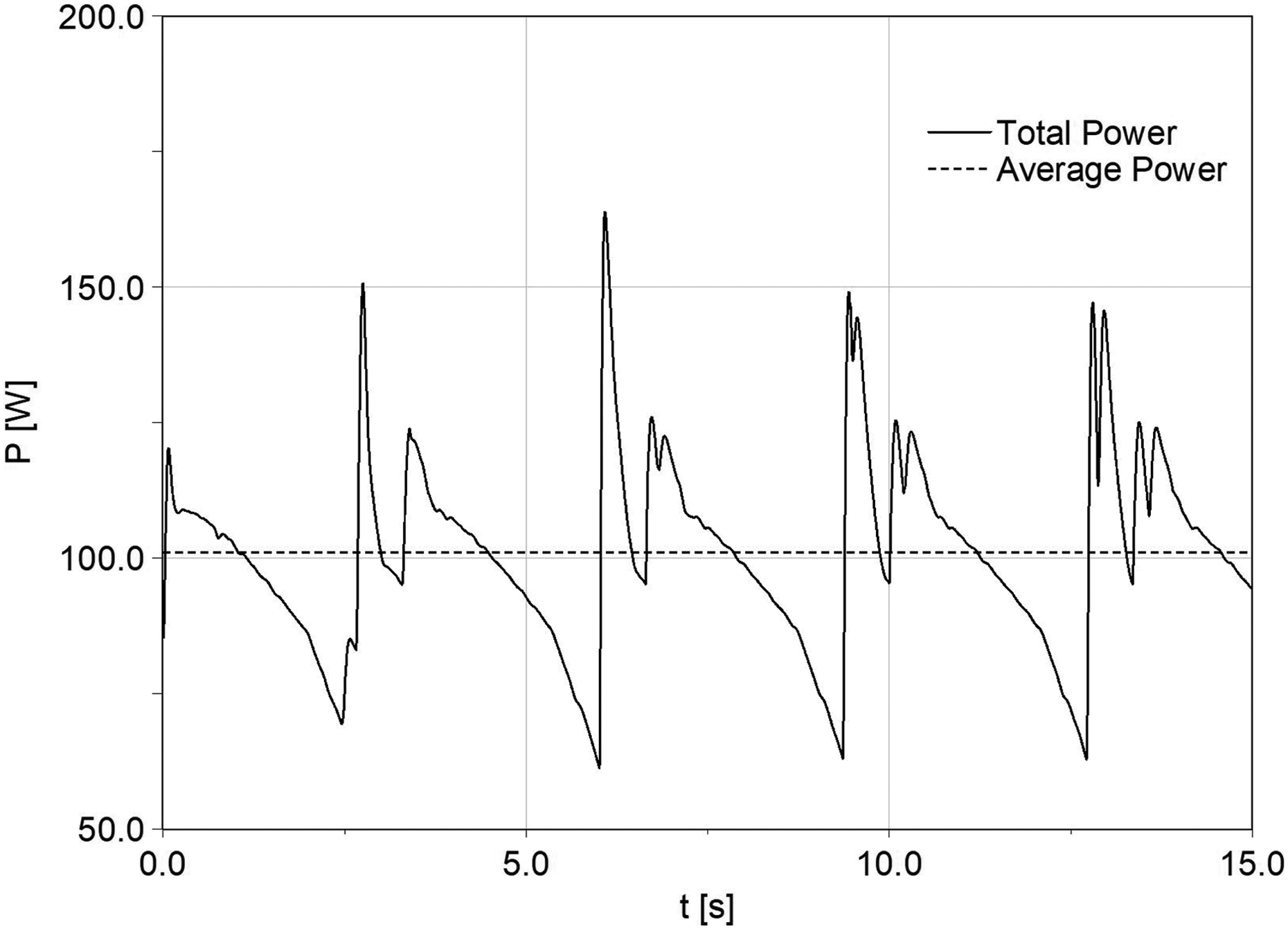
Simulation of the power consumption of the all drives for the translational speed 0.1 m/s in the MSC ADAMS environment.
Conclusion
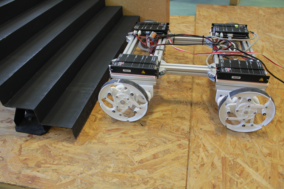
Based on experimental verification of the segmented wheel principle using a scaled plastic model, it can be stated that this solution mode of the wheel for moving on flat ground and for travelling on stairs is fully functional. Despite a number of technical problems, which are currently being addressed and are related to an optimal construction solution of the segmented wheel mechanism together with the solution of a sensor system for scanning the wheel profile and with the development of algorithms to control the wheel movement for an optimal and safe movement on stairs, it seems that finally a solution for the wheel has been found which will provide smooth and rapid movement on flat ground with low energy consumption, as well as an accurate and also smooth and uniform movement while travelling on stairs. At the same time, this wheel is able to overcome obstacles in a non-structured environment such as sand, debris and mud, which will be the subject of further exploration and experiments. Currently, the assembly of an undercarriage with these special wheels at real size has been finished and continues the development of a control software. The undercarriage of the mobile robot is shown in Figure 19.

Mobile robot with the segmented wheels on stairs.
Footnotes
Declaration of conflicting interests
The author(s) declared no potential conflicts of interest with respect to the research, authorship, and/or publication of this article.
Funding
The author(s) disclosed receipt of the following financial support for the research, authorship, and/or publication of this article: This article has been elaborated under support of the project Research Centre of Advanced Mechatronic Systems, reg. no. CZ.02.1.01/0.0/0.0/16_019/0000867 in the frame of the Operational Program Research, Development and Education.