
Abstract
The article describes the concept of a locomotive construction for a robot moving along an urbanized or unstructured natural terrain. The most suitable variant was the development of a hybrid leg-wheel chassis for a service robot. It has only been confirmed that the proposed design solution for the leg-wheel hybrid chassis can largely determine activities, requiring a high degree of mobility in different application environments and, at the same time, a high efficiency motion speed over a relatively flat terrain. The geometry for the middle robot service category was processed to verify mobility. The proposed geometry has been optimized for the obstacles defined by the rescuers’ requirements. The result of the simulation is the mobility verification and the recommendation for the prototype development of the service robot.
Introduction
Walking is a movement that has a high adaptability to the terrain and wheel platforms excel in the speed and efficiency of move. Machines and devices that are built on a wheel platform can move on a relatively flat terrain. The aim of the development of locomotion for service robots is to develop a device that is capable of equating or even overcoming human mobility in a natural environment. Most work in uneven locations is focused on human work, because for this field it is not suitable to use wheels or belts due to very rugged terrain and due to high damage to the substrate. It is necessary to develop a movement system that can move in an unstructured environment. 1 The unstructured environment is distinguished by the fact that it contains gorges; it has a large slope of the terrain, and it is possible to develop only a relatively low relative pressure. During the course of the development, a countless number of wheel and crawler robots were created. These platforms are suitable for their simplicity, energy efficiency and, most importantly, their own static stability. However, even after many years of development, these machines still do not reach the mobility of humans or animals. Although, robot legs have great adaptability in a complicated environment, they have some problems. Generally, robot legs require a large number of action members and a complex mechanism. Moreover, the speed of their walking is slow on a relatively even terrain. 2 These shortcomings can be solved by a combination of a walking and a wheel mechanism.
There are many animals that have the ideal mobility properties; many of the four-legged robots have been engineered to emulate the well-known modes of movement in nature. 3 The advantage of such platform is in achieving static stability using three legs that will be in contact with the ground and their robot centre of gravity will be over this three-legged stand. With such a step, the robot can stop and hold its position at every moment of its signature without losing its stability. 4 These robots are by their nature very slow and have poor energy efficiency not only due to the static stability requirement, but also because of many degrees of freedom in their legs. The complexity of their legs connected with heavy weight of many drives restricts the robot’s behaviour and imposes robots on their frequent failures. 5
To achieve higher speeds, increase efficiency and expand mobility in natural environment, walking robots capable of dynamic movement have been developed. Dynamically stable platforms are designed to maintain stability even when the centre of mass is outside the static stability range. Although movement or walking is stable as a whole, each of the phases that make up the cyclical movement may be unstable. 6 The robot cannot simply stop and hold its position during dynamic run without losing stability. Leg movement can include the flight phase, when no foot is in contact with the ground allowing for higher speed and jump ability. So, a smaller robot with dynamic capabilities can use its kinetic energy to increase the effective size and overcome a larger obstacle. In general, dynamic robots emulate animal behaviour more and have better mobility. Such behaviour, however, usually requires large amounts of energy which makes them more difficult to be equipped with an independent source of energy. 7
To make use of efficiency and simplicity of wheeled robots, as well as their adaptability and chassis manoeuvrability with the legs, many hybrid structures of leg-wheel platform are developed, but these platforms are relatively bulky and complicated structures that go through the terrain relatively slowly. 8
The most exciting sector for the use of hybrid chassis is the use of rescue robots. Robot deployment in the rescue sector is based on the need for partial or fully automatic execution of confinement tasks: risks to the safety of life (personal, working, social and public), the risk of industrial accidents and operational misfortunes (including natural disasters and terrorist acts); the risk of police, security and rescue activities, and the reduction of possible losses from accidents and operational misfortunes.
Hybrid leg-wheel robots
In the world, there are many hybrid robot leg-wheel designs, combining both benefits and providing good terrain mobility and a wide range of speeds. It is assumed that the hybrid robot legs overcome obstacles and heavy terrain, while the wheels move efficiently and reliably on general surfaces; many of these structures have proven themselves in special research conditions. To date, none of them has been able to get into the dynamic sphere, and therefore has great shortcomings in its speed, efficiency and ability to overcome obstacles.
An example from this group, the athlete robot (Figure 1), based on the principle of a group of leg-wheel robots, can be described. It is a six-foot robot that rolls on a hard (rigid) pad with six wheels. When passing through an obstacle or when moving in a soft terrain, the wheels are blocked and the robot moves like a walking system. 9

Robot athlete.
Probably, the best known is the Curiosity robot, which is exploring the Gale Crater on Mars as part of the NASA Mars Science Laboratory mission (Figure 2). The mobility systems are built with six wheels with a diameter of 50 cm. The suspension system served as a chassis for a vehicle, unlike its smaller ancestors. Each wheel has pliers and is independently controlled and adapted to allow climbing in soft sand and combining through rocks. Each front and rear wheel can be independently controlled, allowing the vehicle to swivel into place as well as the arched arcs. Each wheel has a pattern that helps keep its traction, but it also leaves patterned tracks on the sandy surface of Mars. This pattern uses on-board cameras to estimate the distance travelled. Rover is able to climb sand dunes with slopes up to 12.5° Based on the vehicle’s weight, the vehicle can withstand a slope of at least 50°. 10

Robot curiosity.
Another representative is the hybrid mobile robot (HMR), which allows two basic variants of the arrangement, namely wheel variant and leg variant. The transformation is carried out by pivoting the individual joints, the arms being in the form of a semicircle (Figure 3). 11

Robot HMR.
Conceptual chassis design for natural ground movement
To achieve maximum manoeuvrability and overcome obstacles, a six-foot mobile platform is designed, with each foot being completed with a wheel. Such a combination allows to move at a higher speed with simultaneous crossing of the rugged terrain. Other benefits include varying chassis width in a wide range that allows to change the position of the robot’s centre of gravity to suit your current needs. 12
Inspiration is based on the biological model of spider kinematics (Figure 4). This variant of the movement mechanism design is characterized by the following features: The axle distance between the ‘ankle’ and the ‘knee’ is 317 mm and the axial distance between the ‘knee’ and the ‘back’ is 466 mm. The kinematics of the motion mechanism module stems from the spider’s biological model, which is simplified, and the wheel is used to move and improve the energy balance. The foot module is based on the concept of a rotating space leg. The hip joint performs two movements (rotation around the y- and z-axes), and the knee joint rotates around the x-axis. The foot has three degrees of freedom. The wheel module concept is built on a standard 320-mm wheel with an integrated wheel drive. The design of the locking mechanism consists of five parts (Figure 4(b)): the mounting of the wheel module to the foot module (4), the locking mechanism of the chassis frame (1), the upper and the lower part of the module (2 and 3) and the wheel itself (5). To control the movement of mechanism, four servomotors must be used. The first servomotor is being used for foot module. To change the direction of the wheel module, the second and third servomotors are used to rotate the leg module joints and the fourth actuator to drive the wheel module. When applying this design of the motion mechanism into the six-leg-wheel robot assembly, 24 servomotors are needed to control the movement, of which 6 servomotors are used to control the rotation of the individual legs, modulating the direction of the module, 12 for turning the joints of the legs and 6 to drive the individual wheels.
13

Design of wheels.
Various calculation methods can be used to solve kinematics, depending on the complexity of the kinematic structure. For this reason, we used trigonometric relations for calculating the inverse kinematics, which are sufficient for a given calculation. We divided the movement into eight phases, where, for each phase, we have determined the coordinate start. At each stage, we could move up to four joints on one leg. With such a movement (four joints on one leg; Figure 5), we could simplify the change values. For the angular rotation of individual joints, we had to determine several parameters. Conditions are relating to both foot module and the wheel module.

Leg dimensions.
The platform of the mobile platform can be mathematically described using trigonometric relationships


Walking is a cyclical motion caused by a leg movement sequence. One of the basic conditions for a walking robot is to maintain stability (stable attitude) in a predetermined location regardless of its topography. From a mechanical point of view, this can be achieved by the application of at least three legs, which are in direct contact with the ground and the centre of gravity that falls into the supporting polygon. The ability to maintain a statically stable walk is that the motion platform is always supported by at least three points; at least four feet must be applied. The length of the leg was dictated by the platform’s need to overcome obstacles. Referring to Figure 5, it is apparent that using a longer leg length, which extends the robot’s support polygon, the robot gains better ground stability. Increasing the leg length increases the required torque in the joints, resulting in a significant reduction in robot dynamics.
14
For describing the entire robot, it is advantageous to use the Denavit–Hartenberg principle. The Denavit–Hartenberg principle was used to locate the local coordinate systems of the individual legs and to set the transformation matrices.
15
The homogeneous transformation matrix

where

Because joints R2 and R3 are always parallel, multiplying T12 and T23 first and applying sum of angle formulas will yield a somewhat simpler final expression. 16 This can be done whenever two rotational joints have parallel axes, and we have

where we have used the sum of angle formulas


Similarly, a solution for a six-legged robot can be found. Furthermore, an optimal wheel radius is measured within the lengths of each arm. Smaller wheel diameters improve the walking process; however, larger wheel diameters are better suited for moving on a flat surface when overcoming smaller obstacles.
Movement algorithm – walking
Many walk patterns have been developed to control and manage it. In addition, walking speed is not so high and dynamic effects are not as important as for humans. However, for the first tests on middle-class robots, the phase step method should be approached. As a first step, it is necessary to determine the mobile platform walking algorithm (Figure 6) and then, it is possible to phase into the individual steps.

Movement algorithm.
The robot begins to move from the starting position, where the roller kinematics is used (Figure 6(a)).That is used until the wheel is able to overcome the obstacle on the path of its movement. In the case of inability to overcome the obstacle, the kinematics of the robot movement, which starts from the basic position (Figure 6(b)), is used. When walking alone, the three legs are always in contact with the washer, which guarantees the static stability of the robot, and thus, the centre does not have to be transmitted. In the first step, legs (left) of the left (L’Z), left front (L’P) and right middle (PS) legs from A to B point along the straight trajectories (Figure 6(b)) are reached. In the second step, when the legs are pulled out (L’Z, L’P and PS), legs of the left middle (L’S), right back (PZ) and right front (PP) from the point C to the point D along straight trajectory (Figure 6(c)). In the final step, when all legs are in contact with washer, the legs are aligned to the position of the basic posture of the walk (Figure 6(d)). Once the obstacle has been overcome, the robot can move through the wheel drive mechanism or continue walking, but it is preferable to move through the roller the rolling mechanism as it allows faster movement than walking (Figure 6(e)). 17
Simulation of robot movement
The robot may encounter various types of obstacles during the movement within a designated operating space which prevent it from moving further and therefore forced to overcome them. For this reason, the simulation of the obstacle movement was carried out which helped us to verify the movement capabilities of the proposed robot and how it can overcome the obstacles in the course of its movement.
18
We made the simulation on the obstacles (Figure 7), which are characterized by the following basic parameters: Slope type obstacle (Figure 7(a)): This type of obstacle has a set maximum height of 800 mm with a 45° gradient defined by the inner angle of the triangle. Stair type obstacle (Figure 7(b)): This obstacle has a maximum height of 800 mm and an obstacle length of 800 mm.

Various types of obstacles.
The method of moving robot’s leg (Figure 5) was chosen to alternate two types of motion, namely by rolling wheel and walking, and the movement of the six legs using wheel rolls to move along the plane and to walk during moving across the terrain. Walking was used to move using the methods of insect (spider) or horse.
Overtaking a slope-type obstacle can be accomplished by means of a wheel drive, walking or combining mechanism. In the simulations, only the way of using the wheel roller was used. The process of overcoming a given obstacle of the robot is shown in Figure 8, which we have divided into eight movement sections (Figure 8(a) to (h)), each section being characterized by the different behaviours of the robot in its movement. 19 When the robot passes through this obstacle, it is interesting to track the changes in the positioning center of gravity (COG) of individual parts of the chassis frame structure and also of the robot as a function of time (Figure 9).

Move over sloping types of obstacles.
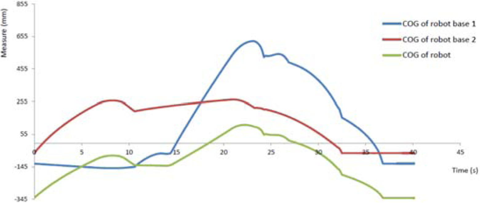
COG diagram of moving over stair types of obstacles.
The obstacle of stair type was simulated using a combination of the methods from rolling wheel to walking. This method of movement, which was chosen, is a hindrance for the faster passage. After selecting the transition method, we were able to implement the simulations that were performed as in the previous type of obstacle. The overcoming of the obstacle is illustrated in Figure 10, which has been divided into 10 movement sections (Figure 10(a) to (j)), each section being characterized by different angular rotations of the individual robot joints in its movement.

Move over sloping types of obstacles.
For a more detailed description of the course of this transition, the individual motion sections, in which the behaviour of the robot joints was described, are detailed. The robot initially moves with the wheels continuously on the pad (Figure10(a)), with the individual joints retaining their starting position. This movement is performed until the robot gets out of the hurdle. Subsequently, its chassis starts to rise to a height that allows it to smoothly cross the obstacle. This stroke performs the knee and hip joints of the movement mechanism’s legs by changing their angular rotation (Figure 10(b)). Once the desired height is reached, the knuckle legs of the motion mechanism hold their current angular rotation value. Subsequently, the forward and left front legs begin to move sequentially, according to the structure of the walking stroke –stepping – tossing, while legs are at the top of the obstacle. After both legs have been pulled, the robot begins to move through the motion mechanism (Figure 10(c)), where this movement takes place until the front legs are in contact with the upper surface of the obstacle. If the front legs reach the boundary position of the contact with the pad, they begin to move by walking, this movement persisting until the pivotal axis of the front legs is obstructed (Figure 10(d)). Subsequently, the front and left rear legs of the movement mechanism gradually move through the walking path, so that their wheels are obstructed after being obstructed and are in contact with a parallel pad. After this movement, the middle legs of the movement mechanism are lifted to a height that allows the robot to cross obstacle without any collision. Then, the robot begins to move using the wheels of the motion mechanism (Figure 10(e)), where wheels from the front and the rear legs are in motion, and in such a movement, we considered the high stiffness of the rotatable joint of the robot. Movement with the wheel roll mechanism takes place when the centre line of the pivot joints is obstructed (Figure 10(f)). Subsequently, after the robot has stopped, the middle legs of the movement mechanism come into contact with the pad by means of the simultaneous movement. Upon reaching the contact, the right rear and left hind legs are progressively moved, and this movement is being realized by walking, which continues until the rear leg wheels are in contact with the upper surface of the obstacle (Figure 10(g)). At the moment of contact, the robot begins to move in a direct motion so that the front and middle legs use the wheel roll mechanism and the rear leg of the movement mechanism (Figure 10(h)), and this combined motion takes place until the axis of the pivot joints is obstructed. Once this position has been reached, the robot stops and the rear legs, in the order of the right rear to the left rear, are obstructed and walked in contact with the washer (Figure 10(i)). With this move, the obstacle is overtaken and the robot moves through the roller mechanism of all wheels (Figure 10(j)) and continues to move along its transport route.
As the robot crosses this obstacle, it is interesting to follow the course of how the angular rotation changes in the individual joints of the motion mechanism. The result is graphical descriptions of these changes on the knee and hip joints. The course of the change of rotation and the speed of the hip joints during the movement is shown in Figure 11.
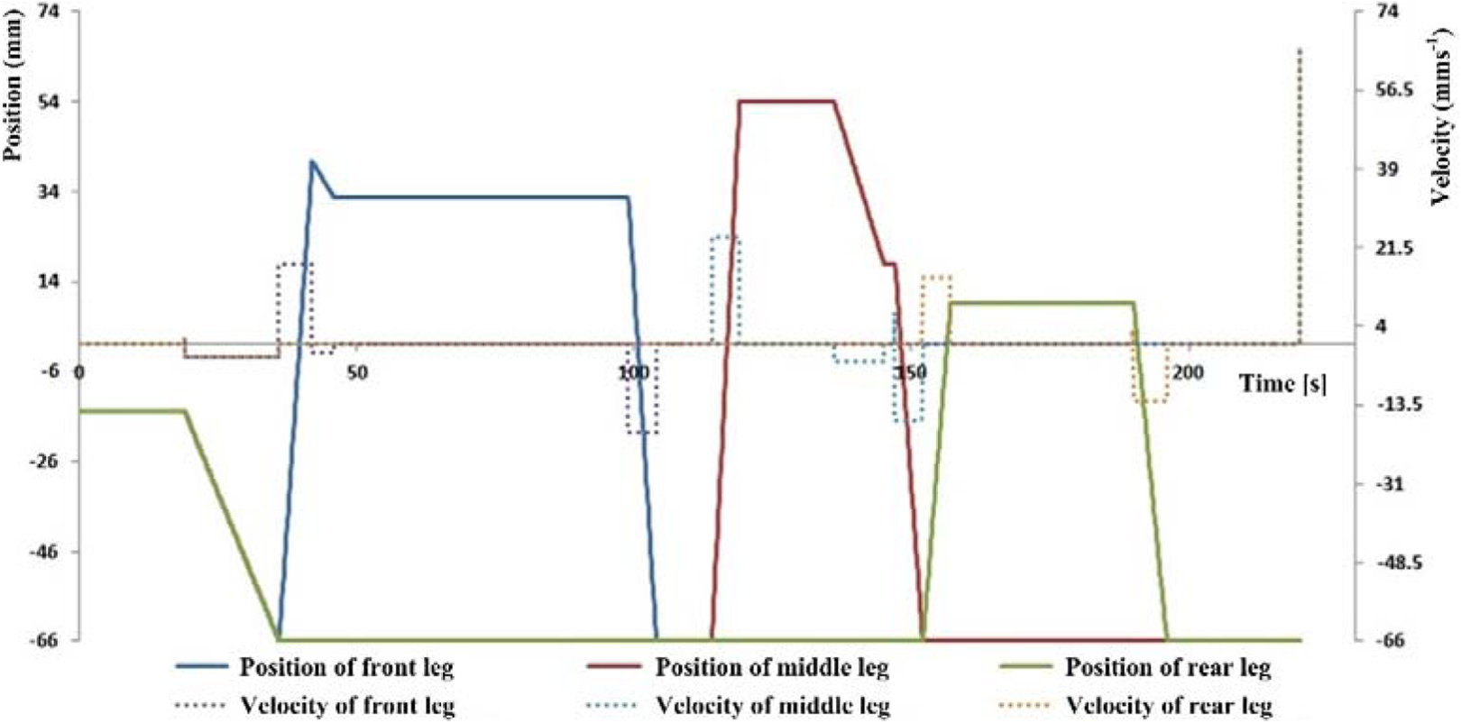
Changing the rotation and speed of the hip joints on the right legs – the obstacle of the step type.
To overcome the last obstacle-type derailment, a combination of movements of the roller and walking roller mechanics has been used as a step-down obstacle. To ensure safe passage through this obstacle, it is necessary that hip and knee joint servomotors of the leg modules and the wheel modules are able to provide the necessary change in the height of the robot chassis from its initial position, the value of which is 580 mm to a position with a maximum value of 50 mm. To enable this change, the hinge joints should change their angular rotation to a maximum of 10° and the knee joints to 165°, and once these positions have been reached, the servomotors of these hinges must be able to maintain this position. During the obstruction of the obstacle, the achieved values change so that the change in the mid and hind legs for the hip joints ranges from 10° to −65° and the knee joints, on the middle and hind legs, continuously move with the spin value of 165°. Hip values for the hip and knee joints on the front legs differ only in the time span from 105 to 115 s when the hip and knee joints reach 42°. Such joints ensure that there is no interruption of the smooth passage of the robot through the obstacle.
Based on these results, it can be stated that, in the mentioned hip and knee joints, the robot is able to overcome the obstacles such as slope and stairs. 20
Conclusions
The first stage for designing the hybrid mobile chassis of service robot was the conceptual design of chassis and through simulation to verify its mobility capabilities. The proposed robot is also able to overcome obstacles in unstructured environments. Based on the results from the simulation that was performed through slope and step obstacles, it can be stated that the selected kinematics of the motion mechanism allows them by appropriate angular rotation of its individual joints to pass over the selected types of obstacles without any collision. This is only confirmed that the chosen concept on the leg-wheel chassis can be established to a large extent of activities that require a high degree of mobility at a different application environment.
At present, the phase of a specific design of the mechanical and electrical parts is in progress. The aim of the whole development is to construct a rescue robot capable of interfering mainly with natural disasters, such as earthquakes, hurricanes and so on. For this reason, a high degree of mobility and a rapid movement at the sites of operation are required.
Footnotes
Acknowledgement
The authors would like to thank the Slovak Grant Agency for its support.
Declaration of conflicting interests
The author(s) declared no potential conflicts of interest with respect to the research, authorship, and/or publication of this article.
Funding
The author(s) disclosed receipt of the following financial support for the research, authorship, and/or publication of this article: This work was financially supported by the Slovak Ministry of Education (project KEGA 054 TUKE-4/2016).