
Abstract
Most inspection and repair works are performed with robots in a nuclear power plant, as a human operator cannot access the facility due to radiation. In order to ensure the integrity of the reactor vessel, the reactor nozzle welds should be inspected periodically. The inspections have been performed using a conventional inspection machine with a large sturdy column; however, these machines are so large and heavy that their handling and maintenance requires much effort. In order to resolve these kinds of problems, the authors have developed a mobile robotic manipulator, which is very small and light and easy to handle. The underwater mobile robot with magnetic wheels is guided by a laser beam for its accurate positioning. Even though the inspection system is light and simple, its accurate positioning for reactor nozzle weld inspection is much more difficult and complex. This article explains how to position our laser-guided mobile robot manipulator at the reactor vessel wall and determines the pan and tilt angle of the laser pan-tilt device to guide the robot along a specified path around the nozzle. We derive the path planning of the mobile robotic manipulator when inspecting nozzle welds on the upper shell of the vessel, and we experimented the whole robotic system to identify position accuracy of the robot movements through the inspection scanning of reactor nozzle.
Introduction
Nuclear power plants use the nuclear fuel to heat water, whereas an electric power plant burns oil or coal to generate high-pressure steam from water. Both power plants supply the steam to a turbine to generate electricity by turning the turbine axle with the steam. The reactor pressure vessel in a nuclear power plant is a thick-walled cylindrical steel vessel enclosing the reactor core in a nuclear power plant, and it contains high-temperature and high-pressure water generated by the nuclear fission of the nuclear fuel. 1 –3 Thus, the vessel should be well made and periodically maintained to ensure its safety. The vessel is located in the center of the containment building in the nuclear power plant, as shown in Figure 1.

Inspection of a reactor pressure vessel in nuclear power plants.
The vessel is made of special fine-grained ferrite steel, well suited for welding and with high toughness. The inside is lined with austenitic steel cladding to protect against corrosion. It is usually manufactured by welding large rolled plates, forged sections, or nozzle pipes. 4 In order to ensure the integrity of the vessel, these welds starting with reactor nozzle welds should be periodically inspected using ultrasonic transducers. Such inspections are usually conducted underwater to minimize any exposure of the radiation from contaminated vessel walls. 5,6
The reactor pressure vessel has a cylindrical shape with inlet and outlet nozzles around the upper shell, as shown in Figure 1. It has many welds, such as a weld of the flange to the upper shell, a circumferential seam, and a weld of the nozzle to the upper shell. Among them, the nozzle weld is the most difficult area to inspect by mobile robot manipulator, as it has a very complex geometry. When manufacturing the reactor vessel, the nozzle is made separately and inserted into the reactor shell and welded together. The nozzle weld is inspected by ultrasonic scanning from the inside of the nozzle wall.
When inspecting the welds of a vessel wall, the reactor head and the reactor internals are moved to the next canal, so that the inspection can be performed efficiently. The reactor vessel is filled with water up to the top of the canal to reduce radiation exposure during the inspection. Thus, the inspection machine must be operated underwater.
The nozzle welds has been typically inspected using a conventional inspection machine with a large column. 7 –10 This type of inspection machine has a central mast manipulator with a three-leg base, which is mounted onto the top flange of the reactor vessel. 11 –13 The manipulator comprises two linear and two rotational axes: a hoist extend, a boom rotator, a boom extend, and a head rotator. 14 The hoist extend moves vertically along the center line of the cylindrical reactor vessel via a telescopic column. The boom rotator refers to the rotation of the vertical axis, and the boom extend stretches the end effector to any part of the vessel, such as the inner wall of the nozzle. The head rotator serves to orient the end effector for the ultrasonic sensor assembly to attach to the wall properly. Unlike a central mast manipulator, some companies have developed a 6-degrees of freedom (DOF) articulated robotic manipulator with a three-leg base which spans the reactor vessel diameter to provide a solid anchor. 15,16
These kinds of manipulator have simple kinematics and easy path planning of the inspection because the base of the manipulator is fixed at known position. However, these manipulators are so huge and heavy that the handling of the system is extremely difficult and it takes much time to inspect the whole reactor welds.
In order to resolve these kinds of problems, the authors have developed a mobile robotic manipulator, which is very small and light and easy to handle. It was generally introduced in our previous paper,
17
especially focused on the laser guidance control. The specially designed manipulator is mounted on a two-wheeled mobile robot platform. The mobile robot can move on the vertical wall of the vessel using a magnetic wheel and is guided by a laser pan-tilt device for accurate positioning of the inspection path. This system should meet the following two requirements. The mobile robotic manipulator should be light enough, so that the entire robot can be attached to the vessel wall by the attraction force generated by the magnetic wheel and buoyance force. The end effector of the manipulator can be attached to any position of the vessel including the nozzle inside with a proper orientation and contact force.
Thus, we designed and optimized a very light 5-DOF manipulator to reduce the unnecessary DOF, whereas the conventional system uses a general 6-DOF manipulator. Although the inspection system is light and simple, the accurate positioning of our robotic manipulator inside the nozzle is much more difficult and complex than that of a conventional inspection machine. The nozzle inspection using an underwater mobile robot guided by a laser pointer requires numerous calculations and a geometric analysis based on the kinematics of the manipulator and the whole reactor vessel system. 18 In order to inspect the nozzle welds accurately, the robot should move precisely to the given position.
This article illustrates the nozzle inspections by our laser-guided mobile robot manipulator. It explains how our mobile robot manipulator is positioned at the reactor vessel wall. The kinematics of the laser-guided mobile robotic system is driven, and the pan and tilt angle of the laser pan-tilt device are obtained to place the mobile robot at the desired position and orientation on the vessel wall. The inverse kinematics of our manipulator for nozzle inspection are obtained graphically. Finally, we derive the path planning of the mobile robotic manipulator when inspecting nozzle welds on the upper shell of the vessel, and we experimented the whole robotic system to identify position accuracy of the robot movements through the inspection scanning of reactor nozzle. The system is small and compact such that it reduces the critical path process for preservice inspections of pressurized water reactors. By deploying two robots simultaneously in the vessel, the overall inspection time can be greatly reduced.
Mobile robotic inspection system
Reactor vessel inspections are carried out underwater. When inspecting the reactor vessel, its hemispherical reactor head is unplugged from the cylindrical vessel body and moved to nearby refueling pool. Our reactor inspection system consists of a reactor inspection robot, a laser pan-tilt device, a main control station, and other supporting components. The laser pan-tilt device is mounted in the center of the crossbeam, which is placed accurately on the flange surface. The underwater mobile robot moves on the vessel wall with four magnetic wheels and is guided by the laser beam emitted from the laser pan-tilt device. 19 –21 The system was introduced in detail in our previous paper, 17 especially focusing on the laser-guided control. Here, the system is introduced briefly to explain the kinematics and the path planning of the robotic system.
The reactor inspection robot is a submarine-type mobile which mainly consists of a main body, locomotion wheels, a manipulator, and a position sensitive device. The robot has four magnetic wheels to climb the vertical wall of the vessel. 22,23 As most of the reactor pressure vessel in a pressurized water reactor (PWR) is composed of carbon steel and shallowly clothed inside with austenitic stainless steel, magnetic wheels can generate attraction force to the vessel wall. Two main wheels are driven by DC servo motors, and both the front and rear caster wheels are mounted on the parallelogram links.
The robot has four floats with a cylindrical shape at each corner of the robot body, as shown in Figure 2. It generates buoyance force to eliminate the robot’s weight, allowing that the robot to become slightly less than or equal to zero in terms of its weight underwater. Most of the electronics and sensors are mounted inside the floats for waterproofing.

LAROB with four magnetic wheels, long-reach manipulator, and PSD. PSD: position sensitive detector.
A long-reach manipulator is mounted on the mobile robot body. The manipulator should be sufficiently light and should be able to reach up to 100 cm. As shown in Figure 2, the robot has a long manipulator with ultrasonic probes attached to its end effector. The manipulator has 5-DOF for active joints and 3-DOF for passive joints. The active joints are the slide, tilt, rotation, four consecutive translations, and probe rotation joints. 17
The position sensitive detector (PSD) assembly is mounted onto the robot body, as shown in Figures 2 and 3. The PSD is a sensor that provides the deviation of the laser beam spot from its center. 24 The PSD is attached onto a small pan-tilt device that is driven, so that the PSD faces the laser beam emitted from the laser pan-tilt device.

Illustration of the kinematics of the reactor inspection.
The laser pan-tilt device is fixed in the middle of the crossbeam across the upper flange of the reactor. The laser pan-tilt device induces the robot to the next position. The laser pan-tilt device emits a laser beam to the next position to which the robot will move. The robot, with the PSD on its back, detects the deviation of the laser beam spot from the center of the PSD and moves in the appropriate direction to make this deviation zero.
With the mobile robot manipulator, we conducted common ultrasonic testing to determine whether or not the welds of the reactor vessel have defects. After the ultrasonic probes attached at the end effector of the robot manipulator emit an ultrasonic wave onto suspect welds, its reflected signals are monitored. The welds to be inspected in the vessel of the pressurized water reactor are largely classified as circumferential welds and nozzle welds. To inspect the nozzle to the middle shell, the manipulator scans the inner wall of the nozzle while the robot travels around the outside of the nozzle entrance with the posture shown in Figure 3. This is the most difficult procedure, as the mobile robot should be accurately guided by the laser pan-tilt device.
Position determination of the laser-guided mobile robot
In order for the robot to inspect the specified weld line, the traveling path of the mobile robot must initially be determined, with the mobile robot located at a specified position on the path with a specified posture while controlling the laser pan-tilt device. For the specified robot position and posture, the pan angle, ϕz
, and the tilt angle, ϕy
, of the laser pan-tilt device should be determined. To do this, the laser-guided mobile robotic system is analyzed kinematically. To develop consistent calculations, we define the coordinate systems as shown in Figure 6(a) and (b):
{Rx} the reactor coordinate system {LAS} the laser coordinate system {NOZ} the nozzle coordinate system {ROB} the robot coordinate system {PSD} the PSD coordinate system {Mi} the manipulator coordinate system
The robot has the position of (X rob, Y rob, Z rob) with respect to coordinate system {Rx} and orientation Φ rob about the z rob-axis. Because the robot is designed to be always parallel to the reactor vessel wall with the aid of parallelogram links, as shown in Figure 4(b), other orientations except for Φ rob are always zero and are thus out of our concern. The robot position can also be represented by the azimuthal angle, Θ rob, and the z-directional position, Z rob, as the robot always works on the cylindrical vessel wall with radius Ro .

Parallelogram links and the robot.
Forward kinematics of the mobile robotic system
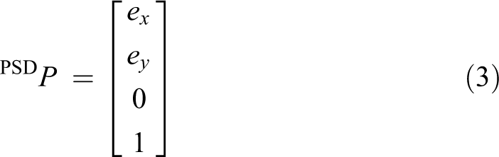
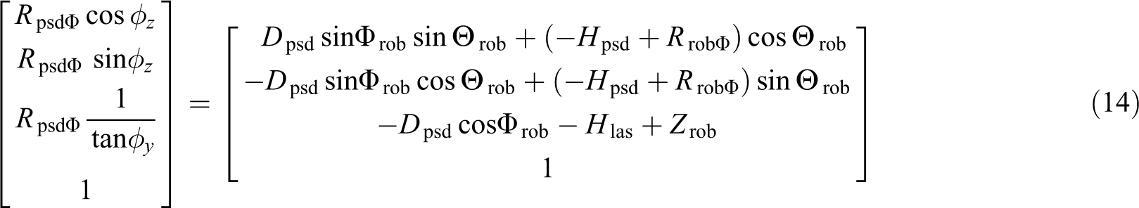
When the laser pan-tilt device emits the laser beam onto the PSD of the robot and the laser beam points at Po on the PSD, which has the position (ex , ey ) with respect to the PSD coordinate system, the question arises of how we can determine the robot position (X rob, Y rob, Z rob). We can measure the pan angle, ϕ z, and the tilt angle, ϕ y, of the laser pan-tilt device, the deviation (ex , ey ) from the PSD, and Φ rob using an inclinometer embedded in the robot.
We can summarize that we have the following: Three unknowns: X
rob, Y
rob, and Z
rob. Five givens: ϕz
, ϕy
, (ex
, ey
), and Φ
rob.
From the equation of the geometric relationship

As a notational convention,
25
AP represents a position vector written in coordinate system {A}, and

where R
psdΦ
denotes the radius of the PSD center from the center of the vessel, which is a function of Φ, the heading angle of the mobile robot, as shown in Figure 3(a). The transformation

while the transformation of the robot coordinate system {ROB} to the PSD coordinate system {PSD} becomes

where “TRANS” denotes the translational transform and “ROT” denotes the rotational transform in the homogeneous form. 23 H psd denotes the height of the PSD from the center of the robot, and D psd denotes the distance of the PSD center from the robot center, as shown in Figure 3(a).
After replacing equations (2), (3), (4), and (5) into each respective side of equation (1), it can be rearranged into the form
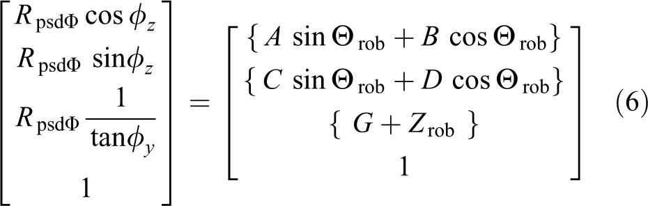
where
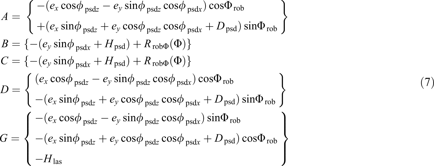
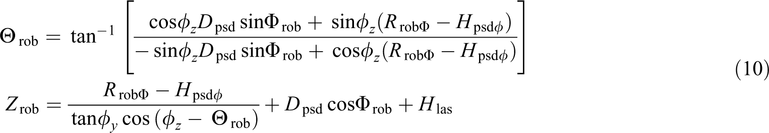
By equalizing each term in equation (6), we obtain the solution with many system-specific variables through a series of calculations

where

Simplified solution
The solution can be simplified if ϕ
psdx
= ϕ
psdz
= 0

and can be simplified even more when ϕ
psdx
= ϕ
psdz
= 0 and ex
= ey
= 0
where

R robΦ is the radius from the reactor center line to the robot center considering the variation in the robot height due to its movement on the curved surface of the cylindrical wall, and D psd and H psd are the position variables, as shown in Figure 3(a).
Robot height variation
It should be noted that R robΦ is a function of Φ rob, as H robΦ , the robot height from the cylindrical wall, varies with the heading angle of the mobile robot, Φ rob. This arises because the robot has a special wheel structure which allows it to move on the cylindrical wall, as shown in Figures 4 and 5. The driving wheel is fixed at the robot body, whereas the caster wheel is fixed at the caster wheel support frame, which can be closer to or away from the robot body.
Path planning of the nozzle welds inspection and scan path calculation around reactor nozzle.
When the robot is moving along a circumferential weld with Φ rob =90°, the caster wheel support frame is closer to the robot body and H robΦ becomes only the radius of the driving wheel, as shown in Figure 4(b). When the robot is moving upward with Φ rob = 0°, H robΦ becomes larger than the radius of the driving wheel, as shown in Figure 4(c).
It should also be noted that R
psdΦ
is a function of Φ
rob and ϕ
psd, which is the length from reactor center line to laser spot Po
on the PSD surface, as shown in Figure 3(a). It can be derived using the equations above. The height of the laser spot on the PSD from the robot center, H
psd
ϕ
, is derived using the following equation

Therefore

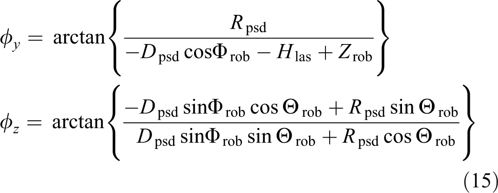
Determination of pan and tilt angles of laser pointer
It is the next issue how to determine the pan angle, ϕz , and the tilt angle, ϕy , of the laser pan-tilt device when we want to place the robot at position (X rob, Y rob, Z rob) with a heading angle of Φ rob.
In this case, we solve the equation of the geometric relationship

where
Through complex calculations, we obtain ϕy
and ϕz
Nozzle inspection by the laser-guided mobile robot manipulator
Path planning for nozzle inspection
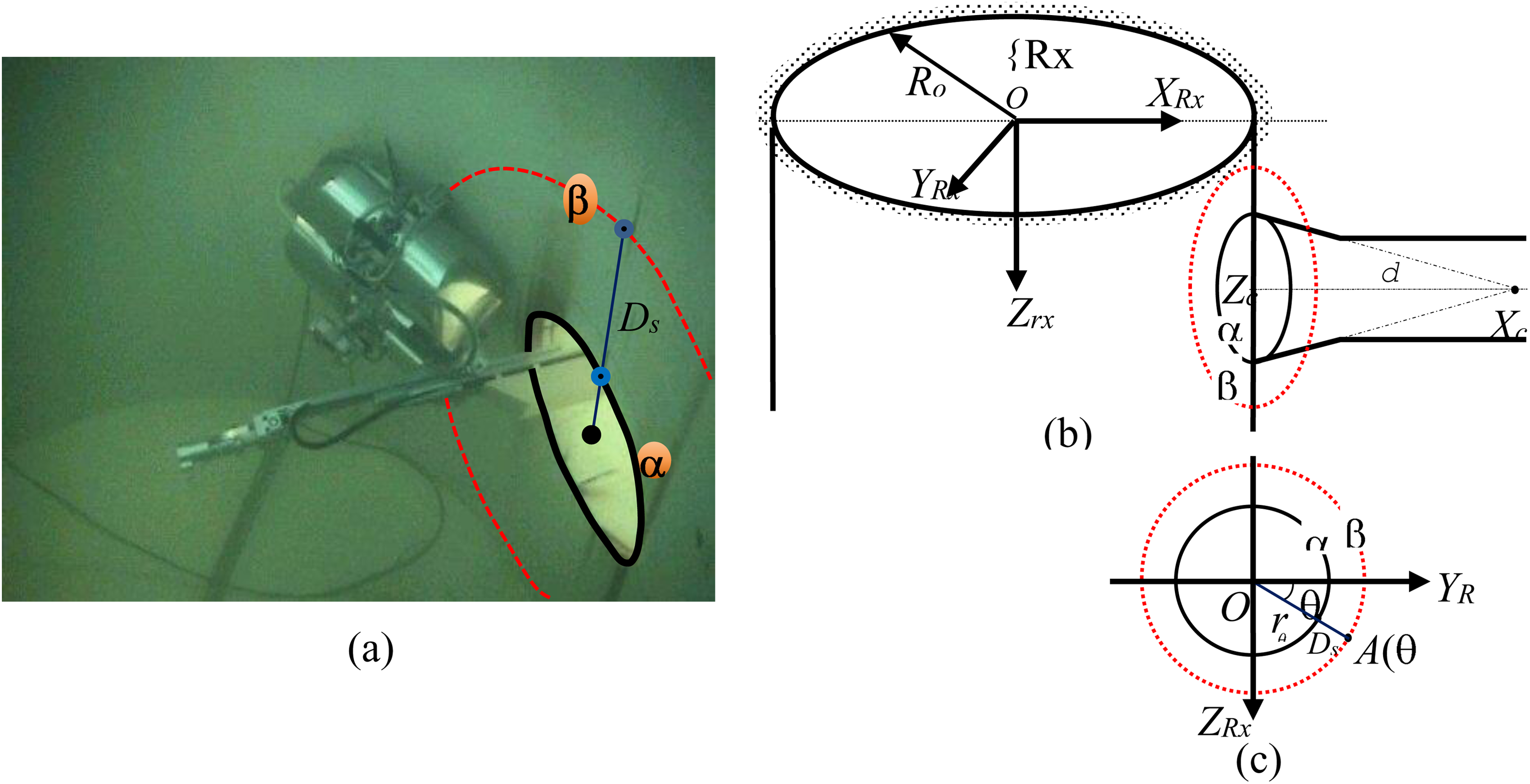
Among the several welds in the reactor vessel, the nozzle weld is the most difficult area to inspect by mobile robot manipulator, as it has a very complex geometry. Thus, we explain nozzle inspections by our laser-guided mobile robot manipulator in this section.
When manufacturing the reactor vessel, the nozzle is made separately and inserted into the reactor shell and welded together, as shown in Figure 3. The nozzle weld is inspected by ultrasonic scanning from the inside of the nozzle wall. Thus, when inspecting the welds around a nozzle, the robot moves around this nozzle (refer to Figure 5).
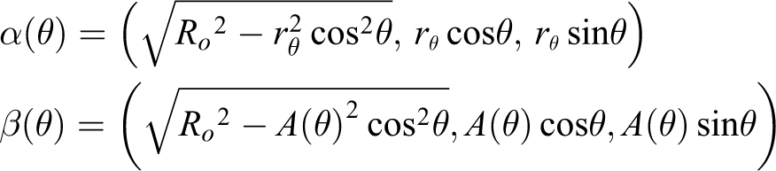
To determine the robot path around the nozzle, β, the equation of the intersection line of both the reactor shell and the nozzle must initially be solved. Because the reactor vessel is cylindrical and the inner wall of the nozzle is conical, their intersection line, α, is made by a cylinder and a cone. Their modeling respect to the reactor coordinate system {Rx} becomes

where Ro
is the inner radius of the reactor vessel in the shape of the cylinder and δ is the cone angle of the nozzle. We can assume Zc to be zero for computational convenience. Thus, the equation of the intersection between the cylinder and the cone is as follows

For computational convenience, let us project this curved line onto the Y–Z plane, as shown in Figure 5(c). When (θ,rθ) is the polar coordinate of a point projected onto the Y–Z plane, the three-dimensional coordinate of the point on the curve, (X, Y, Z), is expressed with the parameter θ

From equations (16) and (23), the equation of rθ becomes
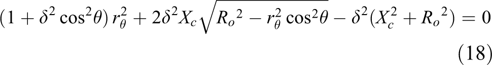
We can obtain the equation of the fourth degree for rθ by moving the second terms of equations (18) to the right-hand side and squaring both sides. We can obtain a solution for rθ for each θ using a numerical method such as the Newton–Raphson algorithm.
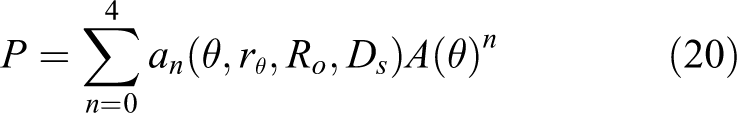
For practical application of the robot movements to nozzle inspection, some mathematical manipulations are additionally needed after these processes. We have to know the trajectory of the robot center, β, along which the robot will move, which is apart from path α with distance Ds . The new path, β, can be expressed as a function of A(θ) with the parameter θ, which is the distance from the nozzle center line. A(θ) is the distance from the nozzle center, which is projected onto the Y–Z plane when θ = θo , that is, (θ,A(θ)) is the polar coordinate of a point on path β projected onto the Y–Z plane.
From equation (23)
Because

By squaring both sides and rearranging into the form of a polynomial of A(θ), we obtain the fourth polynomial of the fourth order. A(θ) can be derived using a numerical method such as the Newton–Raphson algorithm. Thus, we can obtain a solution for X and Y for each Z (or rθ
for each θ).
where

Finally, we obtain the coordinates of the curve by varying the value of Ds at the P polynomial.
Graphical inverse kinematics of the manipulator for nozzle inspections
When solving the inverse kinematics of the manipulator, we have two methods, which are an analytical method and a graphical method. Specifically, when planning the inspection of the welds of the nozzle and the reactor vessel shell, the graphical method is better due to its simplicity and easy understanding by visual intuition. Figure 6 shows the posture of the robot manipulator when inspecting the nozzle weld. In order to achieve contact between the ultrasonic probe and the inner surfaces of the nozzle and to scan along them, we first determine the angle θ
3 for link 4 to be parallel to the inner wall of the nozzle to be scanned


Illustration of the graphical inverse kinematics for inspections of nozzle welds.
From the yellow triangle in Figure 6(a)

we obtain l1

Because the nozzle cone angle is

where
The twist angle θ2 is used for link 3 to direct to center line of the nozzle. It is usually zero, but it is needed to adjust the probe position and is determined experimentally when the robot deviates slightly from the exact path around the nozzle. l
4 is determined for the probe to scan over the weld heat-affected zone. Figure 6(b) applies when
Experiments of reactor nozzle inspection
Experimental overview
With the kinematic analysis derived thus far, we performed a series of experiments with a reactor vessel mock-up and with an actual reactor vessel of a nuclear power plant. As shown in Figure 7, the reactor vessel mock-up is shaped as a cylinder which is 5 m in height and 4 m in diameter, nearly 60% of the size of an actual reactor vessel in a nuclear power plant. For the nozzle inspection experiments, one inlet nozzle and one outlet nozzle were installed. A circular window exists on each nozzle outside the reactor mock-up for partial observations of movements of the robot inside the cylindrical reactor mock-up. The reactor mock-up is covered with a tent to avoid strong sunlight, which prevents proper control of the laser guidance system. The white light of the sun includes the portion of our laser beam frequency. In an actual situation at a nuclear power plant, the reactor vessel is inside the containment building.

Reactor vessel mock-up, the robots lunching and moving underwater.
In this section, we describe the underwater experiments around the nozzles, as in this case, the guidance of the robot is the most complex and because we can check the validity of the entire kinematic analysis derived in the previous sections. We slowly moved the robot slightly to reduce the dynamic characteristics and to check only the kinematics of the robotic system, which includes path planning of the wheeled mobile robot and the kinematics of the manipulator.
The nozzle experiments were performed using the main control computer, whose function is to control the robot and the laser pan-tilt device. It contains the geometric information of all reactor vessels operating in Korea such that inspections can be planned and simulated on a graphical display. On the upper right side of the main display, as shown in Figure 8, the graphic shows a vertical cross-section of the vessel. The planar figure represents a cutaway view of the cylindrical reactor vessel. The main control display has the functions of reactor selection, inspection part selection, robot status assessment, robot location discovery, scan path generation, and robot movement simulation. It also allows the user to move the robot to the start position of the inspection, execute an automatic inspection, and return to the home position after the inspection.
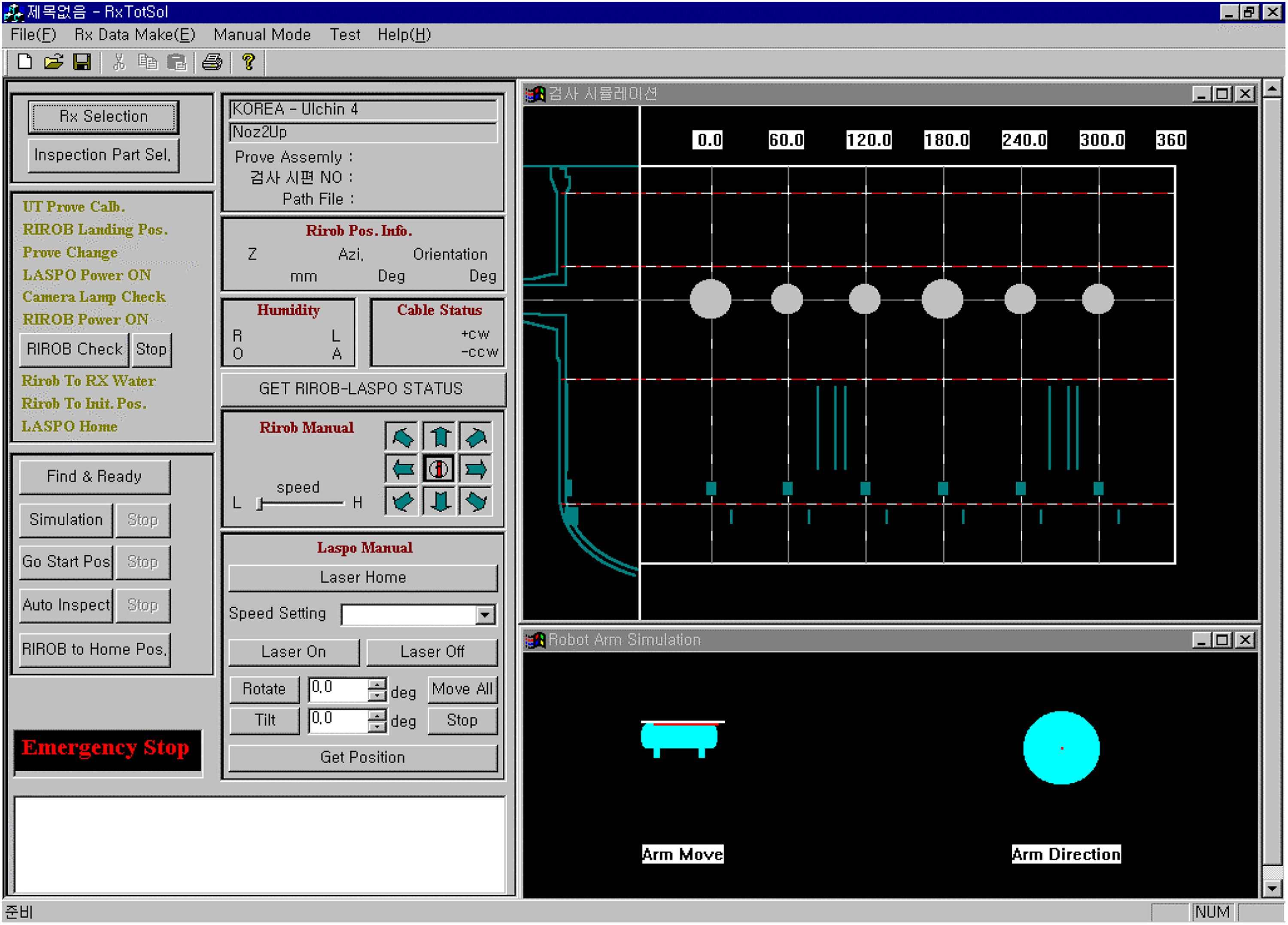
Main display of the main control computer.
During the inspection, the main control system automatically generates the scan path for the robot to move. Simultaneously, the current posture of the robot is displayed graphically, and the image captured by the camera on the robot is also displayed. After the inspection, examination reports are generated using the stored data. The system can also be operated in manual mode during malfunction of the computer control system.
The nozzle inspection experiment is conducted with the main control computer by the following procedures: Select a reactor and inspection part to be inspected. Calculate the robot path around the nozzle by equation (19) and the corresponding pan-tilt angles by equation (15). Finally, calculate the manipulator joint angles by inverse kinematics: equation (21). Simulate the robot movement and display the result on the main console. Check the robot status by itself. Take aim at the PSD on the robot with a laser beam for synchronization. Move the robot to the start position. Execute an automatic inspection according to the inspection plan. Return the robot to the home position in the reactor mock-up after finishing the inspection.
Nozzle scanning and improvements
To check the validity of our kinematic analysis, we chose to undertake a nozzle inspection, as identifying the position of the end effector is convenient through the nozzle window and because the position of the end effector is the final result, which accumulates all position errors from the laser pointer, the mobile robot, and the manipulator.
As shown in Figures 3 and 5, the nozzle inspection is carried out by moving around the nozzle entrance and scanning the nozzle inner wall using an ultrasonic transducer, as shown in Figure 9, which shows an image taken from outside of the mock-up through the nozzle window. First, the robot arrives at the top position of the nozzle (θ = −90° on path β in Figure 5(c)). Second, the manipulator sets the ultrasonic probe at the end effector at the entrance of the nozzle (Os in Figure 9) and stretches it along the line. The robot then moves one step forward along path β in Figure 5 while lifting the probe assembly slightly. The manipulator scans the wall by pulling the end effector. By repeating this procedure, the robot completes the nozzle inspection. In this experiment, the radius of the nozzle is 267 mm and the scanning increments dα is 25 mm.

Scan path of nozzle inspection on the inner wall of the nozzle.
We checked the actual path of the probe assembly on the nozzle wall. The desired position of the end point of each scan was previously marked on the nozzle wall, and we checked the actual position of the end point of each scan. Through numerous experiments and a series of improvements, we finally satisfied the given inspection criteria concerning position accuracy of the robot movements. The criteria state that the ultrasonic transducer attached to the end gripper of the robot manipulator can be located at the desired position with accuracy to a half inch. Thus, we can say that the accuracy of our mobile robotic manipulator system is a half inch with respect to the origin of the reactor coordinate system {Rx}. It is not easy to measure the actual path of the end effector of the manipulator scanning at the inner wall of nozzle, thus we only checked through nozzle window if the end effector deviates from the given path within the range of a half inch. The valid area showing the allowable error range is shown in Figure 9, instead of actual trajectory of the robot movement. The valid area is shown as yellow dotted box, when inspecting the red dashed line. The end effector should not deviate outside of the yellow box.
During the experiments, we faced many problems and improved them. Among them, laser occlusion and inner wheel differences are the most important. Maintaining the line of sight between the laser and the robot is not always possible without occlusion, especially during the execution of nozzle inspection tasks. The manipulator frame hides the laser beam emitted from the laser pan-tilt device to the PSD on the robot when inspecting the nozzle around θ = 3/4 π, as shown in Figure 5. The actual position of laser occlusion can be calculated by solving the intersection between the line of the manipulator and the line connecting the laser pan-tilt and the PSD. In laser occlusion areas, the robot moves while folding the manipulator. Another improvement is the compensation of the inner wheel difference. We previously derived robot path β for nozzle inspections. However, if we guide the mobile robot by the laser beam, the PSD travels along path β but the robot wheels deviate slightly toward the inside of path β. Thus, we compensate for the inner wheel difference. Details are not described here due to page limitations. Thus, we designed a new system considering the necessary improvements noted above and tested the system in an actual reactor vessel in a nuclear power plant, as shown in Figure 10. The underwater experiments can be seen in the form of video. 26

Robot testing in a reactor vessel.
Summary
The conventional inspection machines used in the reactor vessels in a nuclear power plant are so large and heavy that their handling and maintenance require much effort. In order to resolve these types of problems, the authors have developed a mobile robotic manipulator which is very small and light and easy to handle. The specially designed manipulator is mounted onto a two-wheeled mobile robot platform. Although the inspection system is light and simple, the accurate positioning of our robotic manipulator using an underwater mobile robot guided by a laser pointer requires a considerable number of calculations and geometric analyses.
The authors developed the laser-guided underwater mobile robotic system and derived the pan and tilt angle of the laser pan-tilt device to place the mobile robot at the desired position and orientation on the vessel wall. The inverse kinematics of our manipulator was also obtained graphically to inspect nozzle welds. Finally, we derived the path planning of the entire mobile robotic manipulator when inspecting nozzle welds on the upper shell of the vessel. The result was applied to the inspection robot, and reactor nozzle weld inspections were performed. These inspections satisfied the acceptance criteria of position accuracy of a half inch of the end effector of the mobile robot. The proposed method is considered to be applicable to other industries beyond reactor vessel inspections.
Further research studies are considered, such as a sensitivity analysis of the position error of the end effector with respect to the entire inspection system, which has many error sources, as well as an effective laser-avoidance algorithm, compensation of the inner wheel difference of the mobile robot, and motion planning by potential field method. When our system is used practically for reactor vessel inspections instead of conventional machines, a number of benefits can be expected, such as critical path process reductions and improvements in handling safety, examination reliability, positioning accuracy, and other areas.
Footnotes
Author’s note
This article describes part of the study entitled, “Robotic Systems for the Retrieval of Contaminated Waste from Hazardous Zones” under a long-term nuclear research and development program in Korea (NRF-2015M2A7A1000193).
Acknowledgement
The author would like to acknowledge the financial support of this work by the Ministry of Science and Technology, Republic of Korea.
Declaration of conflicting interests
The author(s) declared no potential conflicts of interest with respect to the research, authorship, and/or publication of this article.
Funding
The author(s) disclosed receipt of the following financial support for the research, authorship, and/or publication of this article: This work was financially supported by the Ministry of Science and Technology, Republic of Korea.