
Abstract
This paper presents a kind of mobile robot used for inspecting the cable tunnel online in the dangerous environment. Usually, the calble tunnel is full of poisonous gases after fire, such as CO, CH4, CO2 and so on. Then, the mobile robot is able to tell us whether the tunnel environment is safe or not. In this paper the architecture of the robot is designed at first to meet the motion requirement in the tunnel. These characteristics distinguish the mobile robot from others like compact structure, small size, little weight and easily being carried. Next, the moving mechanism and its kinematics are described. And thus, the operating procedure and experiments are introuduced to validate its reliablity.
Introduction
Up to now, the power transmission cables above ground has brought trouble to the reconstruction of the mansions. With the development of the underground power transmission technology, many big cities construct the underground cable tunnels to provide the extra-high-voltage power. Thus, the situation has taken a favorable turn. But the cable tunnels have the drawbacks of long distance and complex landform. So, in order to guarantee the zero downtime of the cable tunnel in operation, the inspection measures must be taken in advance against the fire accident. At the same time, the poisonous gases, such as CO, CH4, CO2 and so on, are often beyond the acceptable concentration level in the cable tunnel. Thus, it is urgent for us to do the wireless, untouchable, and online inspection and alarm for the cable tunnels (Gregory, B., 2000; Matsumura, M., et al. 2006).
Currently, the infrared fire alarm system is installed along the cable tunnels between three and five meters. It has the shortcomings of being passive and immobile. The more vital problem is that the fixed monitoring system is often incapable of further monitoring after burning. And the fixed fire alarm system cost more for the longer cable tunnel ( Y.Z. Fan & X.H. Shen, 2005 ). Therefore, it is necessary to design a mobile robot for inspecting the cable tunnel in the dangerous environment.
At present, some remote controlled vehicles are developed. Cyclops robot designed by AB Precision Ltd., 2007, can be used for some high-risk environments including improvised explosive device disposal and conventional munitions one. With the weight of 30kg, it's too heavy to use in underground tunnel easily. Foster-Miller TALON robots are another powerful tracked vehicles used by the U.S. military to defuse roadside bombs. But it's much heavier than Cyclops (45kg). ZXPJ01 fire fighting robot studied by Z.F. Xu & C.Q. Xu, 2002, is a multifunction teleoperator with the weight above 80kg, not used in the cable tunnel. Some robots have been developed by Fumitoshi Matsuno, 2007, for search and rescue tasks, but they are not mentioned in a real underground cable tunnel. Though those robots have excellent performances in their reqiured applications, another more cost effective and specialized robots for the cable-tunnel inspection are still needed. Because the cable tunnels have the characteristics of longer distance, deeper under-ground, more complicated topography, bigger hidden fire hazard, more water accumulation, and overstandard concentration of several kinds of poisonous gases, the cable-tunnel inspection robot should meet the need of good mobility, high reliability and easily being carried.
This paper is organized as follows. Section 2 describes the general robot system. Section 3 studies the moving mechanism. And Section 4 analyses the kinematics. The operating procedure and experiments are described in Section 5 and 6. The conclusions are given in section 7.
Architecture of the cable-tunnel inspecting robot
In order to put a robot from a 700mm*700mm square manhole into a one-meter-wide cable-tunnel easily, we should make it small, light and easy to carry. Thus, the system requirement is given as follows:
The dimention of the main body: 420mm long, 320mm wide and 300mm high (not include the antenna). The front arm is more than 200mm long. The moving speed > 24m/min. The weight <20kg. The height of an obstacle < 100mm. Working time>2 hr.
To meet the requirement above, a cable-tunnel inspecting robot is designed. It consists of the moving mechanism and a control system. As illustrated in Fig. 1 and Fig. 2, the symmetric double-crawler is adopted in the moving mechanism. The front arm can rotate from zero to 90°. When it needs putting into a cable tunnel, the robot will make the front arm rise to 90° to pass a small manhole. When it needs crossing an obstacle, the front arm can adjust its tilting angle according to the height. If it needs going across a groove or a water pit, the front arm will fall to zero and extend to horizon. Eight ultrasonic sensors are installed on the sides of the moving mechanism to detect the obstacle.

The structure of the cable-tunnel inspecting robot

The photo of the cable-tunnel inspecting robot.
On the moving mechanism, an endless PTZ camera and a control system are installed. The camera is an outdoor IR day/night image sensor in the small die-cast aluminum package and fits in bad enviroment. The panning and tilting angles of the camera are 360° and 105° respectively. Thus, the camera can give more coverage than multiple fixed ones in cable tunnel. A small infrared thermometer and a laser light are installed on the tilting axis. When the camera pans or tilts, the thermometer can detect the temperature of an object indicated by the laser light in the image captured by the camera.
As illustrated in Fig. 3, the configuration of the robotic control system consists of an electrical control system on the robot, a tele-operator and a monitor. The electrical control system is responsible for the robotic motion and the signal processing. The sensors include the inclinometer, the gyros, the gas sensors (CO, CH4, CO2, O2), the thermometer, IR distance sensors and the Ultrasonic sensors. The robotic motion controller is designed on the TI 2407 DSP. The DSP, the A/D module, the sonar ranging module and the other three DC drivers are connected together by the serial RS 485 bus. The robot is able to work in the autonomous mode in an emergency, such as collision avoidance and a step crossing, and so on. Besides, a portable tele-operator is used to teleoperate the robotic movement. An Intelligent Mantainace Center (IMC) is located farther as a monitor to receive the wireless sensing data via the IEEE 802.11b/g Access Point. Thus, the enviroment of the cable-tunnels can be inspected by the real time online system. Some robotic motion commands can be also received from the IMC.

The configuration of the control system
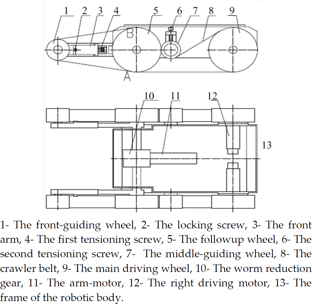
The structure of the moving mechanism
The structure of the moving mechanism for the cable-tunnel inspecting robot is shown in Fig. 4. There are three motors for the robot. One drives the front arm to rotate by a worm reduction gear so as to cross some obstacles, such as cables and a short step. The other two drive the left and right crawlers to rotate respectively. Either of crawler belts is supported by four belt-wheels, i.e. the main driving wheel, the middle-guiding wheel, the followup wheel and the front-guiding wheel (see Fig.4 to Fig.6). All the wheels are installed on a frame of the robotic body.
The structure of the moving mechanism

The structure of the main driving wheel
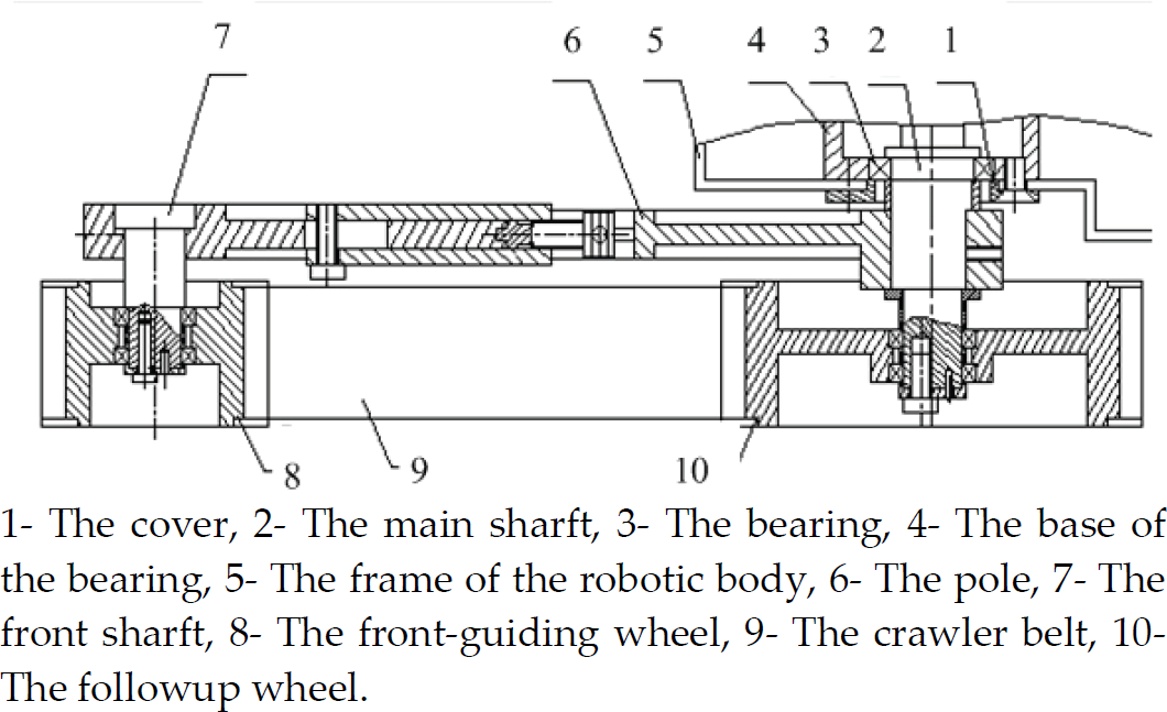
The structure of the front arm
Because the robot adopts only two crawler belts to support the front arm and the frame of the robotic body, the tensioning mechanism is designed to adjust the belt tension.
The crawler belt is engaged with the followup wheel on the A and B points, which divide the belt into front arm part and the body part, as Fig.4 displays. When the first tensioning mechanism is screwed, the distance between the front-guiding wheel and the followup wheel will be adjusted. Then, after the fastening of the locking screw, the belt in the front-arm section is tensioned. When the second tensioning mechanism is screwed, the middle-guiding wheel will move along a small guideway. There is also a fastening screw to keep the tension of the belt in the body section.
The FEM analysis of the robotic body
As illustrated in Fig. 4, the robotic body is the biggest part for the cable-tunnel inspecting robot, in which the wheels and the control system are installed. Designed by the half-close structure, the robotic body is soldered by four side-boards and a bottom-board with 3mm-thick aluminum alloy.
It's necessary to analyze the robotic body using Finite-Element Method (FEM) because the little weight and high strength are required. The 3D model, the meshing result and the FEM analysis digram are shown in Fig. 7, Fig.8 and Fig.9. The analysis shows that, affected by gravity and the tension of the two-crawler belts, the biggest stress and the deformation are acceptable. At the same time, the robotic body is also a light structure less than 3 kg for carrying easily.

The schematic diagram the tensioning mechanism
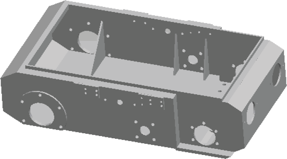
3D model of the robotic body

The meshing result
Differential motion
The differential motion method is used to control the robotic posture. Fig. 10 shows the relationship between the turning radius and the track's speed.

FEM analysis digram
Thus, the turning radius R
0
can be derived by the following formula:

Where,
S is the clearance between the centers of the two crawler belts, V a and V i are the linear velocity of the right and left crawler belt, respectively.
Let the center of the main driving wheel be the origin with the radius R, then a descartesian coordinates is established. Suppose the coordinates of the center of gravity is O(x'0, y'0), the angle between the x' axis and the horizontal line is Φ, the height of an obstacle is h, then we have the following formula from Fig. 11 (W. Merhop, E.M. Hackbarth et al, 1989).


Relationship between the turning radius and the track's speed

The climbing states of robot

The operating procedure of the robot
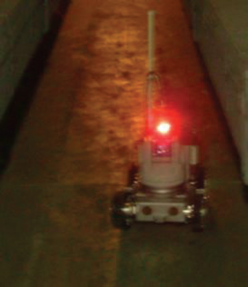
The robot is inspecting
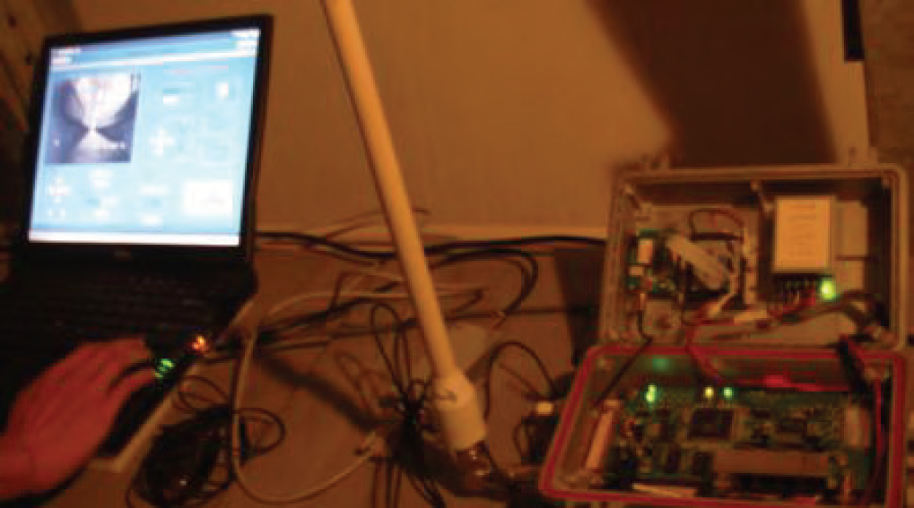
The tele-operator displays the image and data
We can know from the fomula above, the climbing height is determined by the position of the center of gravity and the radius of the main driving wheel. Consider the partial derivative of h with respect to x'0, y'0 and R, we have

Where, φ ∈[0,arctan x'0/y0.
Thus, we can infer that h is the monotone increasing function for x'0, and it is a monotone decreasing function for y'0 and R. Therefore, if the x'0 increases, or y'0 and R decrease, the climbing ability of the robot will improve.
The robot faces the complex tasks as it works as an inspector. Naturally, the tasks will vary from one tunnel to another. Howerer, they are similar in two respects.
First, the putting or hoisting procedures need to be considered. Second, the inspecting procedure should be accounted. For a 700mm*700mm-square manhole, we will adopt a hoisting machine to put the robot into a cable tunnel by a overhead bin. When the bin is placed on the bottom of the manhole, the robot is driven into the cable tunnel. As far as the inspecting method of the robot is concerned, the data collection procedure is described as follows:
First, the camera captures a frame of image and the way of the tunnel is recognized by an image processing algorithm. If the way is blocked, the robot will stop and feedback the status of the tunnel to a monitor. Otherwise, the robot will plan its moving path according to the image processing result. Second, the concentration of gases, like CO, CH4, CO2 and O2 are collected in time.
Because the fire accicdent is usually caused by the cable's high temperature, it's important for the robot to inspect the cable's temperature. Therefore, the temperature at the points on the cables along the tunnel must be detected. All the temperature detection is carried out automatically by the bright laser spot location in a frame of image. So, if the robot needs to detect the cable's temperature, the robotic main driving wheels will stop at first. Then, the endless PTZ camera will rotate along the pan and the tilt axis, when the laser light points at a cable in an image recognized as a bright spot feature, the IR thermometer will mesured the temperature around the spot. Not only the temprature of the cables and the gases' concentration are stored in the memory of the robot, but the data is transfered to tele-operator on an engineering vehicle and a monitor. If the temperature or the gases' concentration is not in a safe scope, a warning signal will be output and the robot will come back to the overhead bin. Finally, the bin is lifted by the hoisting machine.
Experiment
Many experiments have been carried out reliably in the cable tunnels of Yang Gao Zhong Road, Yuan Shen Road and Fuxing Road in Pudong district of Shanghai, P. R. China. Figure 13 shows the robot's inspecting in Fuxing Road cable tunnel. Figure 14 displays the tele-operator and the wireless transmitter and receiver.
We make some tests on motion ability during the experiments. We can control the robot's functions of steering and obstacle avoiding by the image recognition. When encountering an un-surmounting obstacle like the wall according to the image, the robot will stop within a predefined distance which is set according to the moving speed (such as 5m/min, its corresponding distance value is 0.2m). Having adjusted the speeds Va and Vi, the robot can rotate with the desired turning radius according to the formula (1) to avoid the obstacle, and continue to move forward.
When encountering a surmountable obstacle, such as a cable, a doorsill or a step, the robot will attempt to surmount the obstacle. Experimental results indicate that if the feedback from the inclinometer sensor is less than 44°, the obstacle will be surmountable, otherwise it will be insurmountable. Then the robot will move back or rotate. Experiments also show that the surmountable maximum height of obstacle is 105mm.
The scope for warning value of the observed gases' concentrations in a cable tunnel is illustrated in Table 1. As it can be seen from Table 1, the lower CH4 and CO levels found by the robot are, the safer the cable tunnel is. Table 1 also tell us if less than 21.9% volume of air for O2 concentrations is observed by the robot, a warning signals will be occurred. The safe scope of CO2 concentrations is in 300∼500ppm. In our robotic system, when the temperature of a cable in a tunnel is more than 50°C, the warning signals will be output too. If the warning signals were received by the tele-operator/monitor of the cable-tunnel robot, any worker would not be allowed to go down to the tunnel.
Warning values for the sensors

Warning values for the sensors
A cable-tunnel inspecting robot has been presented to detect the dangerous environment of the cable tunnels. In order to have the robot carried easily, a symmetric double-crawler mechanism is designed with a light body structure less than 3 kg. The differential motion and climbing states have been investigated by the kinematics analysis. Moreover, the inspecting method of the robot is described to collect the tunnel image and the concentration data of some poisonous gases. Experimental results indicate that the robot can move smoothly along the tunnels and inspect the environment successfully. The robot also has some potential applications in other dangerous tunnel environment for replacing manual inspection like the road tunnel.
Footnotes
9.
This work was partially supported by the National Natural Science Foundation of China under Grant No. 60675040 and the Science and Technology Project of State Grid of China.