
Abstract
The tail driving system based on linear hypocycloid has the advantages of adjustable phase difference, no quick-return, and combining speed reducer with transformation mechanism. The two-joint composite motion of the driving system was realized via caudal peduncle’s linear reciprocating in cosine and caudal fin’s oscillating in sine-like. First, dynamic and hydrodynamic models were established with momentum theorem, Lagrange theorem, and two-dimensional Foil theory. Second, study on lift force and vortex ring with optimal results was further conducted by numerical simulation in FLUENT. At last, theoretical derivation and simulation results have been testified in experiments.
Introduction
Bionic fish has received extensive attention by biologists, mathematicians and engineers due to its remarkable feats such as high speed, high efficiency and agility. In particular, Carangiform locomotion is one of the most popular swimming modes with better propulsive performances. For this reason, most researchers focus on developing bio-fish prototypes like real Carangiform fish. 1 –3 The classical and simplest tail driving structure of the bio-fish prototype is the linkage but it is different for linkage to swim like multi-joint tail motion. Another technique is to use smart material or a series of steering engines to realize fish’s multi-joint motion. The physical properties of smart materials easily affect the efficiency of the fish tail, and the series of steering engines are controlled by complex electronic system. Therefore, based on linear hypocycloid, we adopted a plane linkage and a special planetary gear set to imitate two-joint tail oscillating with a simple controlled system at low cost. The working principle of the designed driving system is shown in the last part of this section.
The research on the two-joint tail oscillating of the complex linkage 4 established the hydrodynamic model of the two-joint motion based on two-dimensional foil theory, 5 which has been widely accepted and applied by researchers. But the weakness is that they do not present the vortex forming and neglects the fluid–structure interactions. For comparison, we applied a reliable approach, Computational Fluid Dynamics (CFD), 6 –9 in this work to present the caudal fin’s role in controlling and utilizing reverse Karman streets. 10 –13 And based on the dynamic model of CFD, the influence of the vortex structure and the relevant hydrodynamic parameters, such as Reynolds number (Re), the tail-swing frequency, the instantaneous attack angle, and Strouhal number (St), are investigated. 14,15
During past 2 years, based on morphology and kinematics of the live Carangiform fish, two-joint linear hypocycloid tail driving system with a special planetary gear set and a plane linkage was developed. The planetary gear set was composed of V planetary carrier, a fixed sun gear, and two planetary gears. They were installed at the V planetary carrier in two parallel planes, and their reference radius was half that of the sun gear. In the plane linkage, Link and tail fin link were connected to points B and A located at the reference circles of planetary gears, respectively, and the other end of these two links were connected to rotate at point C, as shown in Figure 1.

The working principle of the tail driving system.
The working principle of the bionic fish tail system is shown as: when the two planetary gears 1 and 2 mesh with the sun gear under the driving of the V planetary carrier, point A or B located at the reference circle of the planetary gear 2 or 1 will be reciprocating along the connected line of the point and the sun gear’s central point. In case of points A and B designed at the same diameter of the sun gear, they will reciprocate along the diameter of the line AB with a phase difference decided by the angle of the V planetary carrier. With reciprocating motion of points A and B, a motion triangle ABC in the plane linkage mechanism is formed. As a result, the tail fin link 6 will rotate around the point A and reciprocates together with the point A moving along the AB line.
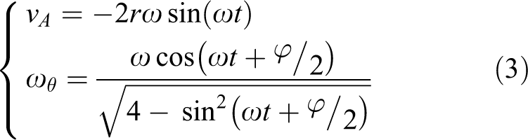
Based on linear hypocycloid, the trajectories of points A, B, and C are presented. The kinematic model of the tail driving system is simplified by structural optimization. The result of structural size optimization shows that only when the length of Link is equal to tail fin link, the tail fin link can oscillate regularly and continuously. Besides, the rod length increases with the growth of the planetary gear’s radius r and the V planetary carrier’s angle ϕ but decreases with the growth of the caudal fin’s swing amplitude θ max. 16 The governing functions of caudal peduncle’s reciprocating motion and caudal fin’s oscillating were shown as

Here, r is the radius of the planetary gear; ω is the angular velocity of planetary gear; θ max is the swing amplitude of caudal fin; and ϕ is the angle of V type planetary carrier.
Two-joint linear hypocycloid tail driving system has a high integrated level with adjustable phase difference between caudal peduncle and tail fin. In this article, based on the kinematic model developed before, dynamic and hydrodynamic models of the driving system would be developed for improving propulsive efficiency with momentum theorem, Lagrange theorem, and two-dimensional foil theory. After caudal fin’s oscillating in FLUENT 15.0, the hydrodynamic performance of the driving system would be conducted, and vortexes would be analyzed. Finally, the experimental validation of the designed system would be presented.
Structure of the two-joint linear hypocycloid tail driving system
Based on the linear reciprocating characteristics of linear hypocycloid and the tail features of aquatic tuna, the tail driving system was designed as a composite mechanism with a linear hypocycloid planetary gear train and a linkage. The proposed planetary gear train worked for caudal peduncle’s reciprocating motion, and the linkage worked together with the planetary gear train to form a motion triangle to realize a composite of caudal peduncle’s reciprocating and tail fin’s oscillating, as shown in Figure 2. This linear hypocycloid driving mechanism has advantages such as combining with speed reducers, no quick-return motion, high reliability, and adjustable phase difference between caudal peduncle and tail fin.

The three-dimensional structure of the driving system.
In most double-jointed robotic fish in latest studies, the caudal peduncle actually runs an arc

Motion model of the driving system.
As referred to the kinematics model of the tail driving system in the first section, the analogous-sine equation of caudal fin’s oscillating angle was different from others. When amplitude of the oscillating angle θ
max ≤ 45ο, analogous sine curve of oscillating angle correlated more closely to sine

Analogous-sine curve via sine curve. 20
Here, there was a phase difference Δϕ between caudal peduncle reciprocating along Z-axis and tail fin oscillating around point A, which was an important parameter for tail propulsion. In the designed physical model, Δϕ was not matched with the angle of planetary carrierϕ. From the table 1, the relationship of them was
Relationship of phase difference Δϕ and planetary carrier’s angle ϕ.

Hydrodynamics analysis of the linear hypocycloid tail driving system
To gain a better propulsive efficiency, according to characteristics of the linear hypocycloid driving mechanism, the output torque of tail fin was deduced by Momentum theorem and Lagrange theorem, the thrust and lateral forces were deduced by “two-dimensional foil theory.” Above all, the efficient power of tail fin oscillation, the input power, and the propulsive efficiency of the proposed driving system would be developed in detail.
In this article, the main content presents the influences of the bionic tail driving system on propulsive efficiency, and considering the high cost of the tail driving system, the lunate tail fin was adopted preferentially. Here, the tail fin and the caudal peduncle were moving on the same plane XOY. Here, the potential energy EP = 0, the energy of the whole tail driving system L was equal to kinematic energy EK . Based on Lagrange function, the torque equation of the driving system could be defined as

For this system, M
i represented generalized forces, specialized as the force F of caudal peduncle and the oscillating torque M
2 of tail fin; qi
represented generalized coordinates, specialized as SA
and θ; and
By combining caudal peduncle’s motion velocity vA with caudal fin’s oscillating velocity vθ by vector method, the velocity of mass center of caudal fin v 2 could be obtained as

where vθ
is the relative velocity of tail fin rotating around point A and deduced as
Then, the kinetic energy produced by caudal peduncle’s motion and caudal fin’s swing could be deduced as

where J is the rotational inertia of caudal fin’s swing and
According to the governing function of kinetic energy,

where m 1 and m 2 are the mass of caudal peduncle and tail fin, respectively. And their centroid positions are located at their geometric centers; aA is the acceleration of caudal peduncle; and αθ is the angular acceleration of tail fin.
In each cycle, the driving system provides the total power

where v 0 is the water speed and flows to X-axis positive direction. R T is efficient thrust along the propulsive direction, which could be obtained by lift force analysis.
Assuming that the caudal peduncle was moving along Z-axis positive direction and the tail fin was oscillating around point A clockwise, the total velocity of the caudal fin’s surface was shown as Figure 5(a). Firstly, the speed of water flowing into caudal fin’s surface vc was shown as


Hydrodynamics analysis view. (a) Model of lift force and (b) Diagram of the relative velocities.
The speed on the caudal fin’s surface was achieved by caudal fin oscillating around point A. Then, the absolute velocity vp of mass center on the tail surface could be expressed as

From Figure 5(a), the lift force R L was perpendicular to vp . As the tail fin was still simplified as a 2D waving plate, 5 and the lift force was shown as

where ρ is the density of water. In this physical model, caudal peduncle is reciprocating rather than oscillating, so the incidence angle of tail fin could be replaced by the oscillating angle
The thrust R T is the component force of R L along propulsive direction OX and could be derived as

where β is the angle between lift R L and axle OX.
Then, the thrust force coefficient and the lateral force coefficient of this designed bionic fish could be deduced as
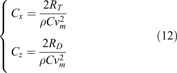
where vm
is the maximum flow velocity of the tail fin, and
Names of velocities.

Numerical simulations on the tail driving system
In this section, propulsive performance of tail driving system was numerically simulated based on optimal parameters in FLUENT software, and further analysis on vortex rings would be developed to verify the feasibility of the tail driving system. The simulation parameters with oscillation frequency f=1 Hz and flow velocity v0 = 0.4m/s are given to match the experimental study.
Visual analysis of the vortex ring
In this article, the tail fin with NACA0012 shape was directly adopted for numerical simulation. With dynamic mesh technique and UDF package in FLUENT, the tail composite motion was realized by using DEFINE_CG_MOTION which could define tail fin’s oscillating with θ(t) and caudal peduncle’s motion with S A(t). The viscous model is based on k − ω SST model. The coupling between the pressure and the velocity is achieved by pressure implicit split operator (PISO) algorithm. Here, in order to simulate the developing boundary layer flow on the swing tail fin, the current study should adopt unstructured mesh. The dynamics mesh was employed to model the flapping motion of tails by using “Spring-based smoothing” method. Additionally, the overall computational domain was divided into kernel and non-kernel areas. In the kernel area, the size of the cells should be 1/20 or 1/30 of the characteristic chord length of tail. 19
The tail vortex formation is presented in Figure 6. At

The evolution of wake vortexes during one period. The evolution is presented by velocity vector field at T/4, T/2, 3/4T, and T. Flow velocity is represented by the blue vectors plotted over a color background indicating flow vorticity, and the directions of wake flow are plotted by black or red streamlines: (a) instantaneous streamlines of developed vortex 1 and converging vortex 2 at T/4; (b) instantaneous streamlines of weakening vortex 1 and enhancing vortex 2 at T/2; (c) instantaneous streamlines of weakening vortex 1 and developed vortex 2 at 3/4T; and (d) instantaneous streamlines of vortex 1, vortex 2, and vortex 3 at T. Besides, two vortex rings are plotted by black lines, the lift RL, thrust RT, and lateral force RD produced by the vortex ring are shown.
Above all, the generation of wake was unsteady and instantaneous with one vortex forming and another dissipating. Due to the influence of gravity and the velocity of flow fluid, the completed vortex moved down, which led to measure errors and coupled motile errors.
From Figure 6(d), the reverse Karman street 1 and 2 interacted to form a single-row ring with perpendicular distance H=4r and half of wavelength
The values of parameters in the Figure 6(d).

Besides, there was a stronger jet perpendicular to the axis of vortex ring. Because this jet reacted on the tail fin, tail fin oscillation generated a lift force R L. Apparently, one component force of R L in the propulsive direction was thrust R T, and the other component in the Z-axis was lateral force R D.
Experiments
Based on the above analysis, the experimental platform of linear hypocycloid tail driving system of bionics has been developed, as shown in Figure 7. When the bionic tuna’s tail fin was oscillating under water, thrust and lateral force acted on the caudal fin could be constantly monitored and recorded by force sensors, as presented in Figure 7(b).

The experimental device platform. (a) The tail driving system and (b) the power driving system.
According to the proposed experimental platform, eight experiments were carried out to obtain values of hydrodynamic coefficient. The average values of thrust and lateral force coefficient from experiments compared with theoretical derivation are shown in Figure 9. The theoretical hydrodynamic coefficient has a periodical change, which confirms basically to experimental results. Regardless of theoretical and experimental hydrodynamic coefficient, the amplitude of lateral force coefficient is larger than that of thrust coefficient, but the time-average lateral force coefficient

The swimming behaviors of the tail driving system in one period. (a) T/4, θ 1 = 0°, (b) T/2, θ 2 = 30°, (c) 3/4T, θ 3 = 0° and (d) T, θ 4 = −30°
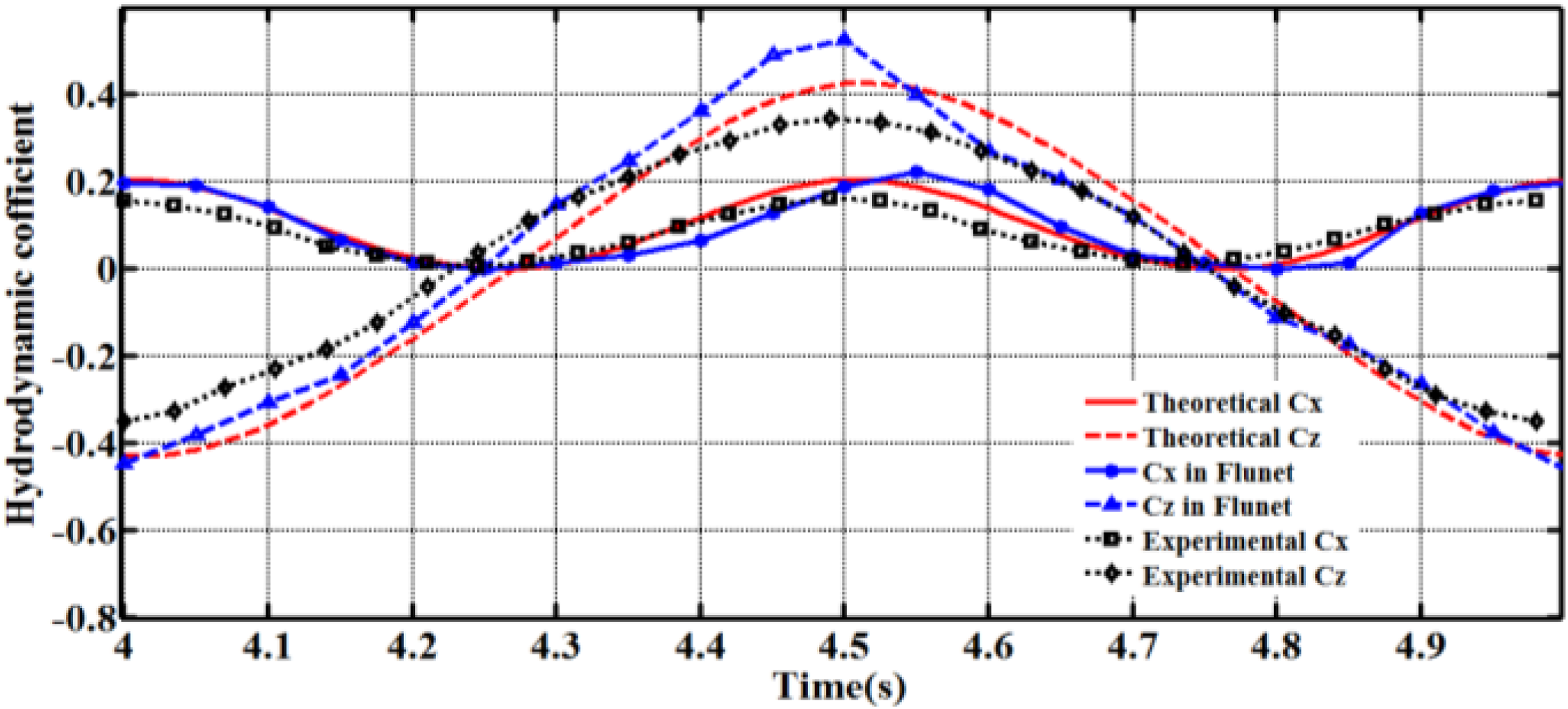
Comparisons of hydrodynamic coefficient between theoretical and experimental.
Conclusion
Based on the designed driving system, dynamic model, hydrodynamics and optimization of kinematic and structural parameters have been developed comprehensively. The hydrodynamic model of the two-joint bionic fish has been developed based on caudal peduncle’s reciprocating.
With the above optimal size, numerical simulation of the driving system have been conducted in FLUENT to make the flow field around tail fin’s oscillating visible. From the numerical simulation, the size and strength of developed vortexes are equal but opposite in direction, and these vortexes interact to form a single-row ring, which confirms to other explorers’ research.
Compared to change trend of the further experiments, the time-average thrust coefficients of numerical, theoretical, and experimental study are all positive when they change periodically, but the average lateral coefficients are zero. The resulting consistency verified the feasibility of the designed driving system, which would hold a solid basis for the future underwater propulsion.
Footnotes
Declaration of conflicting interests
The author(s) declared no potential conflicts of interest with respect to the research, authorship, and/or publication of this article.
Funding
The author(s) disclosed receipt of the following financial support for the research, authorship, and/or publication of this article: This research is financially supported by National Nature Science Foundation of China (No.51205173).