
Abstract
The tail driving system based on linear hypocycloid has the advantages of adjustable phase difference, no quick-return, and combining speed reducer with transformation mechanism. The plane complex movement of the driving system was realized via a motion triangle with a linear hypocycloid planetary gear train and a linkage. In this article, we approach the question of which kind of parameter design can make this driving system more efficient in swimming from a hydrodynamic perspective. First, dynamic and hydrodynamic models were established with momentum theorem, Lagrange theorem, and two-dimensional foil theory. And then, hydrodynamic optimization on kinematic parameters (i.e. caudal peduncle’s reciprocation velocity and caudal fin swing angle) and structural parameters (i.e. swing amplitude, V planetary carrier’s angle, and sun gear’s radius) for a better propulsive efficiency was developed in detail. Second, influences of structural parameters on vortex ring were further conducted by numerical simulation in FLUENT. Finally, the prototype and experimental platform of the designed driving system were established, and the theoretical derivation of lift and lateral forces was testified by experiment.
Introduction
Instead of using propellers, bionic fish accomplished swimming with body deformation and fin movements has stimulated extensive attention by biologists, mathematicians, and engineers due to its remarkable feats such as speed, efficiency, and agility. In particular, carangiform locomotion is one of the most popular swimming modes due to its movements mainly restricted to the last third of the body. For this reason, bio-fish prototypes to imitate real carangiform fish have been developed by researchers just like mushrooms after rain.1–3
Since the 1980s, the robotic carangiform fish such as RoboTuna, RoboPike, SPC-I/II/III, and Essex-G9 have come out.4–6 Specially, the researchers of Pasadena City College have designed a robotic fish with springs. The application of the springs could not only act as robotic skeleton but also absorb some energy of the motor. 7 In Tokyo University of science and technology, the two-joint robotic dolphin has been developed with the crank, rocker mechanism. The robotic mechanism is simple, but its joints were driven by springs, which led to the difficulty in controlling oscillation angles of the caudal fin. 8 In china, the guide rods and hydraulic system were applied to imitate the swim bladder of the robotic fish. 9 This structure was good for robotic fish swimming up and down in the water. But it lacked the diving system of propulsion, and it was impossible to propel forward.
In the aspect of theory, “Two-dimensional Foil Theory” is proposed by Wu, 10 in his study on swimming propulsion with utilizing potential flow theory, which has been widely applied by researchers. Computational Fluid Dynamics (CFD) is a reliable approach to evaluate hydrodynamic performance because of the fact that CFD can provide high-fidelity representation of fluid–structure interactions. The tuna caudal fin’s role in controlling and utilizing reverse Karman street to improve the propulsive efficiency has been studied with CFD.11,12 Furthermore, the influence of the vortex structure and the propulsive efficiency by relevant hydrodynamic parameters, such as Reynolds number (Re), the tail-swing frequency, the instantaneous attack angle, and Strouhal number St, have been investigated. 13
The two-joint composite motion of the tail driving system based on linear hypocycloid was realized by a composite mechanism with a linear hypocycloid planetary gear train and a linkage. Structural or kinematic parameters such as reciprocation velocity, swing angle, the reference circle of the planetary gear, the angle of the V type planetary carrier, and the joint position on the caudal fin link will play important role in its propulsive performance. In this article, based on hydrodynamic models developed for the driving system, hydrodynamic optimization on kinematic or structural parameters for a better propulsive efficiency was developed in detail. Second, influences of structural parameters on vortex ring were further conducted by numerical simulation in FLUENT. Finally, the prototype and experimental platform of the designed driving system were established, and the theoretical derivation of lift and lateral forces was testified by experiment.
Structure of the two-joint linear hypocycloid tail driving system
The caudal fin of aquatic tuna acts nearly in a planar composite movement with caudal peduncle’s reciprocation and caudal fin’s oscillation. Here, the tail driving system was designed as a motion triangle to imitate the caudal fin’s motion with a linear hypocycloid planetary gear train and a linkage. The structure of the driving mechanism was shown in Figure 1(b), and the detailed working principle, shown as Figure 1(a), is represented as follows: Point A and point B are separately located at the reference circles of the two planetary gears, and the reference circle of the planetary gear was half of the sun gear. When the two planetary gears 1 and 2 were meshing with the sun gear driven by the V planetary carrier, point A and B would then reciprocate along diameter line OA and OB separately with a phase difference decided by the angle of the V planetary carrier. Point A, point B and the connected point C were working together to form a motion triangle ABC. Based on the motion triangle ABC, the caudal fin link AC would not only rotate around the point A to imitate caudal fin’s oscillation but also moved with the point A to imitate caudal peduncle’s reciprocation.
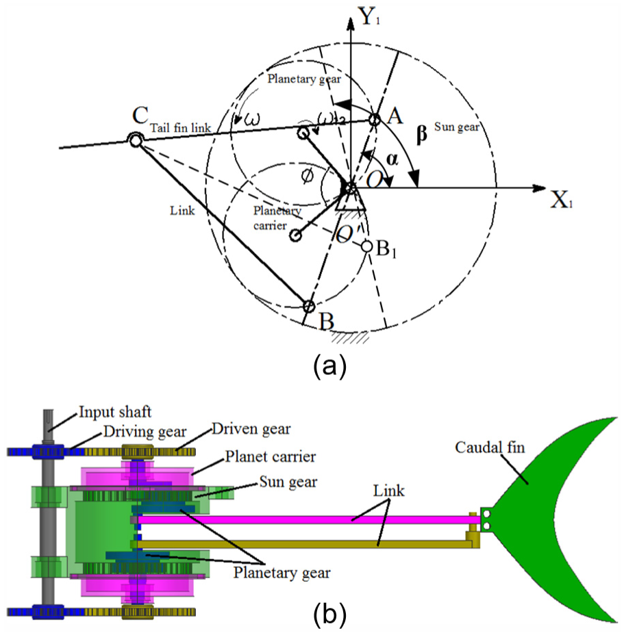
The working mechanism and the structure of the driving system: (a) the working principle and (b) 3D structure.
Based on the planetary gear train, with the reference circle of the planetary gear half of the sun gear, the motion equations of point A and point B could be described as

According to geometrical relationship among the length of the motion triangle

To gain caudal fin’s oscillation in symmetric, the length of the link must be satisfied with the equation

Here, r is the reference circle radius of planetary gear, which is half to sun gear.
From equations (1)–(3), the caudal peduncle’s reciprocating with point A is only decided by the structure parameter of the planetary gear and the angular velocity of the V planetary carrier. The maximum oscillating angle is not only decided by planetary gear’s structure parameter but also linkage’s such as the radius of planetary gear r, the angle of V type planetary carrier
Hydrodynamics analysis of the linear hypocycloid tail driving system
To gain the propulsive efficiency of the driving system, the following hypotheses have been done:
The caudal fin was rigid, and the caudal fin was identically moving in a plane.
Without considering the loss energy of the motor, the output power of the motor is identically equal to the total power of the driving system.
The total energy of a system L was the sum of the potential energy P plus the kinematic energy K, that is L = P+K. Here, with the hypothesis that the caudal fin was identically moving in a plane, the potential energy P = 0, so the energy L of the driving system was equal to the kinematic energy K. Based on Lagrange function, the torque equation of the driving system could be defined as

Here, Mi represents the force F of caudal peduncle or the oscillating torque M2 of caudal fin,

With equations (2) and (4), the force of caudal peduncle F and output torque of caudal fin M2 could be derived as

where m1 and m2 are the mass of caudal peduncle and caudal fin, and centroid positions are located at their geometric centers, respectively; l is the length of caudal fin; az is the acceleration of caudal peduncle; and
Here, the total power of the driving system could be deduced by (Figure 2)

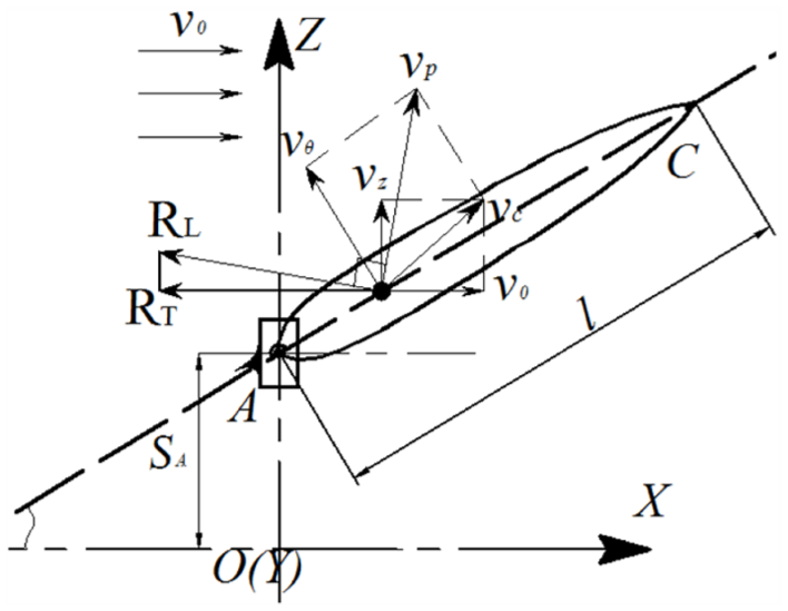
Hydrodynamics analysis view.
Then, the output power could be gained from the product of the efficient thrust and the propulsive velocity. The efficient thrust was along the propulsive direction, which could be obtained by lift force analysis. Here, the caudal fin is still simplified as a two-dimensional (2D) waving plate, 5 and the lift force and the efficient thrust could be gained by

where ρ is the density of water and
The propulsive velocity

where
Above all, the propulsive efficiency

In addition, according to equation (7), the thrust force coefficient of this designed system could be derived as

where Vm is the maximum flow velocity of the caudal fin, and
Wen et al.
16
indicate that attack angle would also affect thrust, and live fish could achieve a higher propulsive efficiency by an optimal attack angle. In the designed mechanism, the attack angle

Parameter optimization
Generally speaking, propulsive efficiency
Kinematic parameters optimization
Here, the surface velocity of caudal fin and oscillating angle would impact on thrust of bionic fish; as a result, it would lead to the change of propulsive efficiency. In the design, the relationship between these correlated velocities and the thrust

From Figure 3(a), the thrust RT, propulsive velocity

The influence of kinematic parameters: (a) caudal peduncle’s velocity via
The influence of the propulsive efficiency and structure parameters
Based on the optimal result of kinematic parameter, optimal oscillation amplitude

The relationship between swing amplitude and propulsive velocity.
Substituting
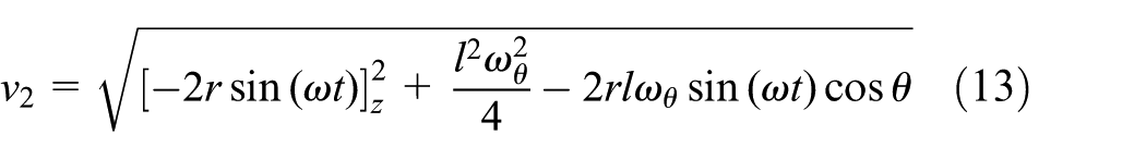
Figure 5 presented that with the V planetary carrier’s angle

The relationship between V planetary carrier’s angle and propulsive velocity.
As seen in Figure 6, the propulsive velocity
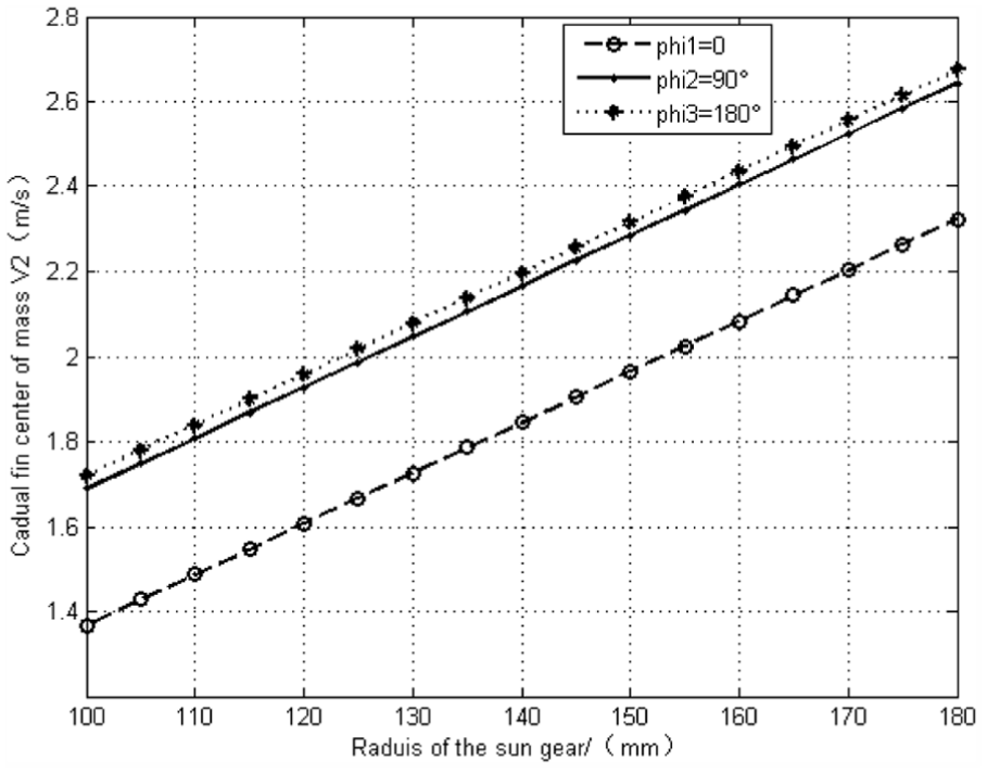
The influence of sun gear’s radius.
According to the optimal structure result, we chose sun gear’s radius r = 150 mm, the planetary carrier’s angle
Numerical simulations on the tail driving system
In this section, propulsive performance of tail driving system was numerically simulated in FLUENT Software and further influences of structural sizes on vortex rings would be developed to verify the feasibility of the tail driving system.
Numerical solver set-up
Here, the caudal fin with NACA0012 shape was directly adopted for numerical simulation. The size of the computational domain was

The boundary conditions of the tail oscillating.
Refer to Aureli’s and Tafuni’s research on Reynolds number,18,19 turbulence model of numerical simulation was determined to Reynolds number. Only when

where L is the characteristic length of the tail,
Substituting the flow velocity
Fixed parameters set-up
Essentially, a better propulsive performance came from a high utilization of vortexes. According to the structural optimization and observation results of live fish, when the phase difference
Based on proposed fixed parameters, and substituting these parameters into equations (2) and (11), the motion equations of caudal peduncle and caudal fin could be obtained as

Figure 8 represents the temporal evolution of oscillating angle
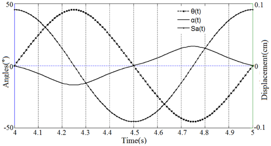
Temporal evolution of oscillating angle, displacement and resulting attack angle.
The influences of structure sizes on vortexes
The generation of wake was unsteady and instantaneous with one vortex forming and another dissipating. According to equation (14), the wake of the tail oscillating with sun gear’s radius r = 150 mm, oscillating amplitude

The wake structure with r = 150,
The primary cause of robotic fish swimming was ring generated by vortexes. We obtained structural sizes of rings with different structural parameters of the tail driving system and listed their detail information, as shown in Figure 10 and Table 1.
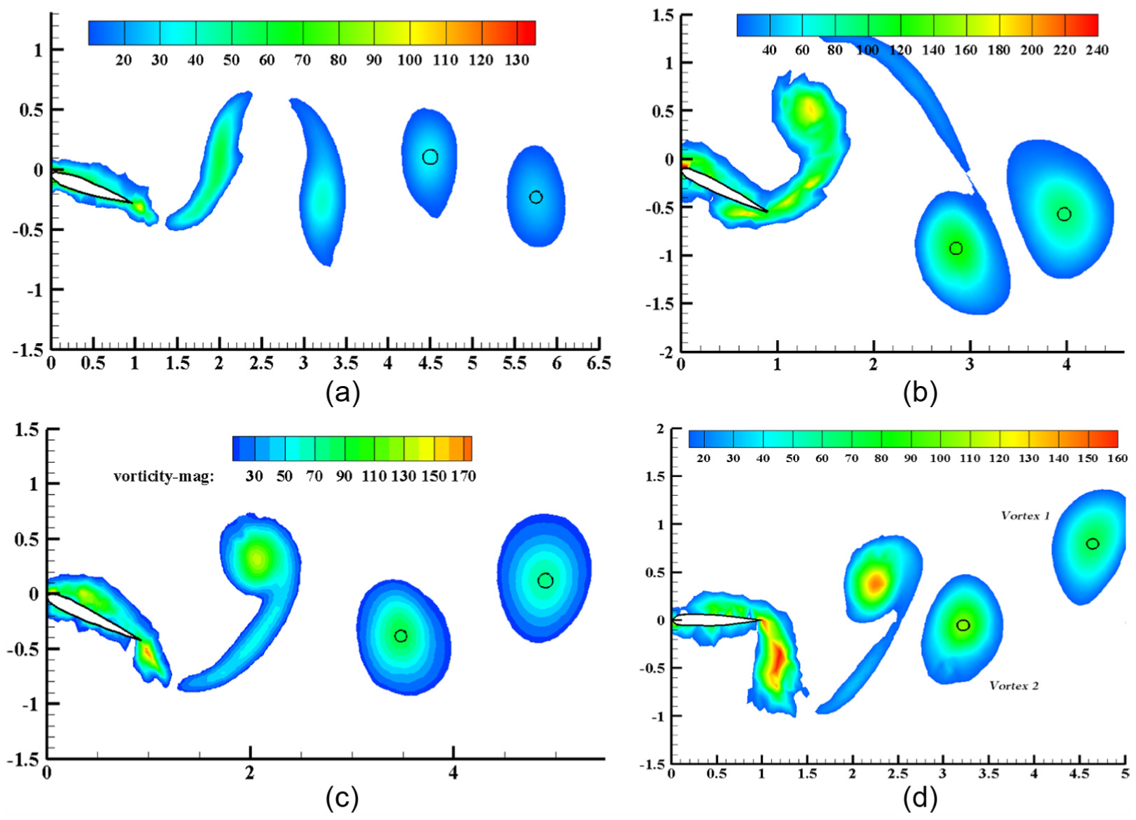
The numerical vortexes with difference structural parameters: (a) r = 150, θmax = 15°; (b) r = 150, θmax = 45°; (c) θmax = 30°, r = 120 mm; and (d) θmax = 30°, r = 180 mm.
The measure values of two vortexes with difference structural parameters.
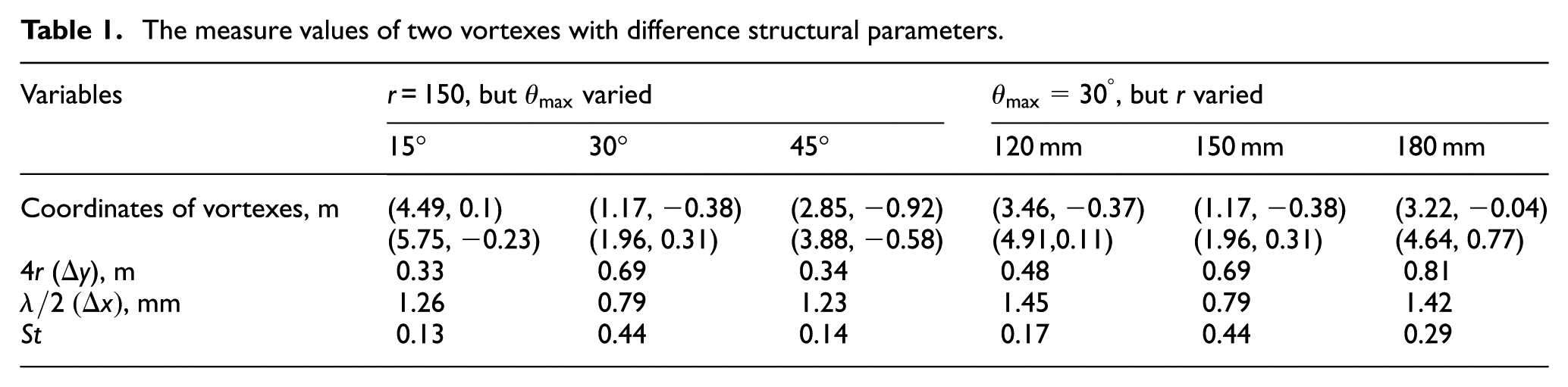
Due to the influence of gravity and the velocity of flow fluid, the completed vortex moved down, which led to measure errors and coupled motile errors. From Table 1, the perpendicular distance of the vortex ring was up to sun gear’s radius, and when r = 150 and
Experiments
Based on the above and the optimized parameters r = 150,
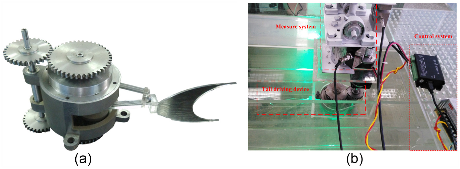
The experimental device platform: (a) the tail driving prototype and (b) the power driving system.
This measure system was composed of force and torque sensor. The tension sensor and torque sensor were mounted on the up-plate of acrylic carriers. But the servo motor was mounted on the down-plate of acrylic carriers to make its output shaft connect to the input shaft of the tail driving device. The acrylic carriers were hung on the slider which was looped on the circular guide rail, as shown in Figure 12(a). Here, the circular guide rail was adopted to weaken the influences of robotic fish sloshing. Because of the changes in caudal fin’s oscillating angles, the measure system should be rotated with the amplitude of 20°.

The control platform of the tail driving system: (a) The measure system and (b) The control system.
For the control system, as shown in Figure 12(b), the controller of the servo motor was directly connected to direct-current power (DC power) and a computer by USB. First, the experimental equipment of the tail driving system should be debugged by virtual control software-9010 on the computer. After the tail driving system rotating smoothly, thrust and lateral force could be constantly gathered by force sensors and monitored by software-M400. Then, these gathered data were substituted into equation (10) to obtain thrust and lateral force coefficient.
In order to obtain average values of thrust and lateral force coefficient, eight experiments have been conducted. The scatter diagram is shown in Figure 13.

The scatter diagram of hydrodynamic coefficients obtained by eight experiments.
The average values of thrust and lateral force coefficient from experiments compared with theoretical derivation are shown in Figure 14. The theoretical hydrodynamic coefficient has a periodical change, which confirms basically to experimental. Regardless of theoretical and experimental hydrodynamic coefficient, the amplitude of lateral force coefficient is larger than that of thrust coefficient, but the time-average lateral force efficient
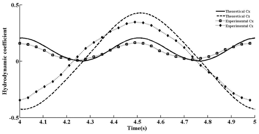
Comparison of theoretical and experimental hydrodynamic coefficients.
Conclusion
Based on the designed driving system, dynamic model, hydrodynamics, and optimization of kinematic and structural parameters have been developed comprehensively.
The hydrodynamic model of the two-joint bionic fish has been developed based on caudal peduncle’s reciprocation. Optimal results based on hydrodynamics show that thrust
Numerical simulation of the driving system has been conducted in FLUENT to study the influences of structural sizes on the robotic fish’s propulsive efficiency. In the visible flow field around caudal fin oscillation, structural sizes of the vortex ring have been studied. The influences of structural sizes of the tail driving system on vortex rings have been developed in FLUENT. The result showed that the perpendicular distance of the vortex ring was up to sun gear’s radius, and when r = 150 and
With the optimal structure parameters with
Footnotes
Academic Editor: M Affan Badar
Declaration of conflicting interests
The author(s) declared no potential conflicts of interest with respect to the research, authorship, and/or publication of this article.
Funding
The author(s) disclosed receipt of the following financial support for the research, authorship, and/or publication of this article: This research was financially supported by National Nature Science Foundation of China (No. 51205173).