
Abstract
Planetary rovers with folding functions can solve the contradiction between the limited space of the vehicle and the functional diversity of the rover and greatly improve the efficiency–cost ratio of space launch activities. In this article, the multi-constrained quadrilateral suspension is considered based on the practical requirements of planetary detection. Based on graph theory and metamorphic theory, the structural characteristics and movement patterns of the rover are analyzed, the configuration transforming process of adding or decreasing the number of rods and kinematic pairs during folding is studied, and the corresponding mathematical model is established. The suspension of the rover is divided into three basic units, and the folding study is performed around each unit. The folding set of each unit type is given, and a feasible folding set is selected for each type of unit according to their structural characteristics and constraint conditions. At the same time, 15-folding schemes for the rover are given, and the optimal scheme is determined. According to the final folding scheme of the rover, the principle prototype of the rover is developed, and the functional experiment of the folding and unfolding is performed. The experimental results verify the feasibility and rationality of the folding scheme, indicating that the developed detection vehicle has a large fold ratio, which can fully adapt to the limited space inside the rocket. The theoretical and technical results can provide technical support for the engineering application of subsequent rovers with folding.
Keywords
Introduction
Foldable structures, which were originally applied to architecture, are widely used in deep space exploration. These structures are a good solution to the problems associated with transporting and launching large space structures. 1 –4 Since the advent of the “Courage” and “Soggner” retractable planetary rovers, using planetary rovers with retractable performance has been studied around the world. 5 –7 Cordes et al. designed a wheel-leg hybrid exploration rover suspension that can be folded and unfolded to adapt to the terrain, thus improving maneuverability and obstacle clearance. 8 –10 Kucherenko et al. achieved a larger folding ratio by folding the four wheels of the ExoMars rover to reduce the length and height of the rover. 11 To ensure a safe landing on the surface of Mars, Novak et al. proposed a Mars concept rover named the Mars 2020 rover which folds the suspension by changing the angle between the rocker arms and the bogie, so that they may be coated by the airbag. The “Tri-Star IV” three-wheeled rover, developed by Aoki et al., has a large folding ratio by gathering the three wheels together through rotated suspension joints. 12 Wu et al. decreased the distance between the wheel hubs and the folding of the suspension by folding the wheels under the rover through the screw, gear, and other transmission devices, thus reducing the rover size. 13 At present, the carrying capacity and storage space of rockets are still limited. This work has solved the contradiction between the volume and functional diversity of planetary rovers. Although many configurations of rovers with a folding function have been proposed, they are still in the stages of performance analysis for the proposed configurations; therefore, few methods or theories are used to guide the folding specific configurations of the rover suspension.
In this article, the kinematic chain of the rover suspension mechanism is divided to determine the smallest unit of these mechanisms. With these minimum divisions as the basic unit, the mutation and fusion of these units are studied according to metamorphic mechanisms and the ways that cells divide and fuse. The method of folding the rover suspension is developed, and the folding scheme of the multi-constrained quadrilateral rover suspension is obtained. In addition, the principle prototype of the multi-constrained quadrilateral rover is developed, the experimental folding and unfolding of the rover suspension is performed, and the validity of the suspension function is proven.
The smallest unit of the retractable suspension mechanism
In the configuration synthesis, the low-pair kinematic chain of the full rotation pair is the most representative, and other types can be obtained by mechanism evolution. 14 For a closed-chain topological graph with a low subplane, when the number of vertices and edges are given, the following formula is satisfied

where L is the independent loop number in the topology, e the total number of edges in the topology, v the total number of vertices in the topology, and k the branch number in the topology.
For the connected graph, from equation (1), the basic circuit number is

From Simoni et al., 15 in a nondegenerate kinematic chain, the greater the loop number of a rod is, the greater the number of kinematic pairs can be connected. Therefore, the maximum value of the kinematic pairs to which a rod can be connected is given by the following equation

where k max is the maximum number of edges that can be connected to each vertex.
In the topology corresponding to the kinematic chain, if vk is the number of vertices connecting a point to a k-edge, called the k-degree point, which can be expressed as deg(vk ) = k. Then, the maximum value of any vertex in the topological graph can be expressed as follows

According to Euler’s theorem, in a planar closed-chain topology, the following formula holds
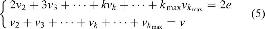
From equations (2) –(5), it can be seen that the combination (4,4,1) can form only one loop without forming a rigid subchain, as shown in Figure 1.
The (4,4,1) loop.
By summarizing recently developed planetary rovers, it can be seen that the number of unilateral suspension rods is generally below 11, with most of them being below 5, considering the simple structure, reliability, light weight, and ease of control.
The suspension of the rover must have definite movement while the rover is in operation. For the passive adaptive suspension structure, the degree of freedom, F, is 1; thus, the rod and kinematic pair synthesis of the suspension can be performed according to the following formula (where the kinematic pairs are planar lower pairs)

According to graph theory, the relationship between the number of independent loops and the number of sides and pairs in a planar topology is

According to equations (6) and (7), the number of unilateral suspension links, pairs, and independent loops is given in Table 1.
Link–pair–independent loop combinations of single suspension.

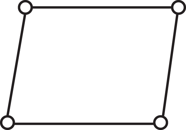
While the combination (2,1,0) is an open-chain structure, the remaining combinations are closed-chain structures. First, determine the largest number of independent loops that each combination can contain. Second, find the independent loop with the largest number of edges in the compositions (6,7,2), (8,10,3) (10,13,4), and (12,16,5). Third, according to equations (2) –(5), let the first and the last independent loops contain the least number of edges. Then, the topological graphs with four combinations is obtained, as shown in Figure 2.
Topological graphs for four combinations. (a) (6,7,2), (b) (8,10,3), (c) (10,13,4), and (d) (12,16,5).
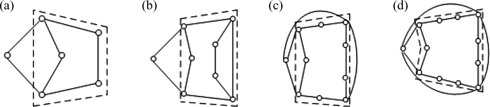
The portions enclosed by the broken lines in Figures 1 and 2 are listed separately, as shown in Figure 3.
It can be seen from Figure 3 that the combination (4,4,1) is the closed-chain mechanism with the least number of edges, and its degree of freedom, F, is 1, making it have a definite motion. The other combinations have the following degrees of freedom: F(5,5,1) = 2, F(7,7,1) = 4, F(9,9,1) = 6, and F(11,11,1) = 8, which can be combined on the basis of adding a certain amount of vertices. The kinematic chain topology shown in Figure 3 can be represented by the exploded view shown in Figure 4.

Decomposition process from complex link elements to simple link elements.
In addition to the several kinematic chains shown in Figure 4, there are other kinematic chains that can be similarly decomposed. As seen from Figure 4, any closed-chain mechanism can be decomposed into the simplest four-bar linkage with some of the open-chain links connected by appropriate kinematic pairs. Therefore, it can be considered that the independent rod and the four-bar linkage are the two basic units that constitute the kinematic chain of the mechanism.
Study on variation and fusion of basic unit
The process of combining the independent rods and the four-bar mechanisms into a complete kinematic chain involves changing the number of degrees of freedom and the number of rods. This process consists of multiple configurations, which can be described by the metamorphic theory, and it reflects the continuity of the configurations in the process of mechanism change. The metamorphic mechanism has the characteristics of the traditional mechanism and embodies the biological characteristics in the multistage configuration change. Therefore, we can learn from cellular division in biology to study the change process.
Cells are the basic unit of organism structures and functions. Similarly, independent rods and four-bar mechanisms are the basic units of kinematic chains. In addition to natural factors, cell genetics and variation are the main engine of evolution and the development of organisms. Similarly, the variation of the basic unit and the fusion between the units is an effective method to develop and improve the kinematic chain.
Variation of basic unit
There are five kinds of variations of the basic unit in the kinematic chain: the number of links, the number of kinematic pairs, the characteristics of rods, the characteristics of kinematic pairs, and the adjacency relationship. The variation in the link number is achieved by increasing or decreasing the number of links in the unit. The variation in the kinematic pair number is achieved by increasing or decreasing the number of pairs in the unit. The variation in the rod characteristics is achieved by changing the rigidity or flexibility of rods in the unit. The variation in the kinematic pair characteristics is achieved by changing the connection between rods in the unit. In this article, only the variations of the rigid rod configuration are studied, and the change of rod characteristics is not taken into account.
Unit variation from decreasing the rods
Although decreasing the variation in the rods has a variety of variants, the calculus process can be summarized in the following steps.
16
List the matrix of the adjacent relationship between the initial configuration rods of the mechanism, usually m × m order, where m is the number of initial configuration rods. Determine the corresponding transformation relationship. If the q (q ≤ m) rod is merged into the p (p ≤ m, p ≠ q) rod, then the corresponding row and column elements of q are added to the corresponding row and column elements of p. This process operation uses a modulo 2 algorithm,
17
which is 0 + 0 = 0, 1 + 1 = 0, 1 + 0 = 1. Remove the corresponding row and column elements of q obtained in step (2), which gives the transformed metamorphic adjacent matrix and completes the transformation. Repeat steps (1) to (3) to obtain the final metamorphic adjacent matrix.
Suppose the adjacent matrix of the initial topology configuration in the metamorphic mechanism is denoted by
Suppose r is the number of stages in the metamorphic mechanism, then the kinematic chain topology of any stages, i, corresponds to an adjacent matrix

where

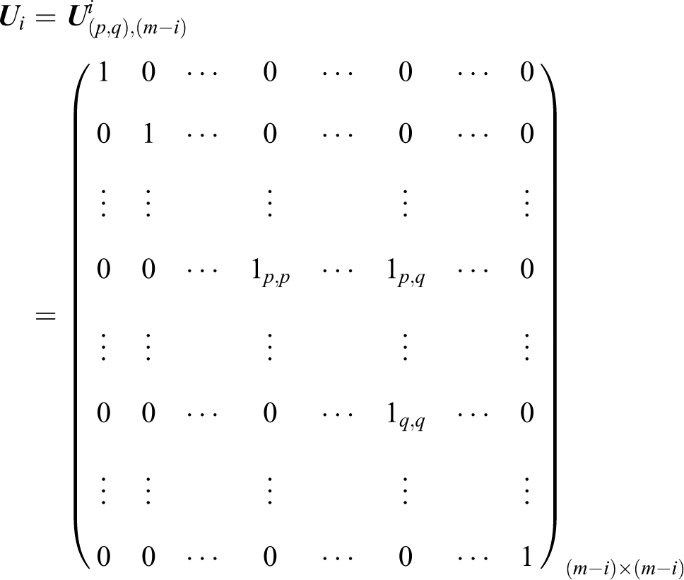

The elementary matrix is used to add the adjacency relation of q row and q column elements to the corresponding elements of p rows and p columns in configuration i. Then,

Increasing unit variation of rods
The configural transformation of the increasing number of the metamorphic mechanism rods can be expressed using the above mathematical model for decreasing the number of rods. The specific method is as follows. For an initial closed-chain mechanism consisting of m rods, after a rod is added to form a new closed-chain mechanism of (m + 1) rods that satisfies a certain connection requirement, the closed-chain mechanism composed of (m + 2) rods can be constructed on the basis of the initial closed chain. With the objective of merging rods, the mathematic model can be used to obtain the required (m + 1) rod adjacent matrix expression. With this, the number of rods is increased in comparison to the initial closed-chain mechanism.
Therefore, the (m + 1) rod closed chain can be obtained by combining the corresponding rods according to the specific requirements based on the (m + 2) closed-chain mechanism.
Unit variation of the adjacency relation between variable rods
Conformational transformation without changing the number of rods implies that various new mechanisms are obtained through the transformation of the topology, which is to change the adjacency relation between the various rods. The final adjacent matrix can be rewritten as follows

where r is the rth working stage after transformation of the initial stage;

where t and w are the serial numbers of the two rods that change in accordance with the adjacent relationship.
When the adjacent relation between rods t and w is initialized, the corresponding row and column elements are 1 in the
Unit variation of the variable kinematic pair characteristics
Unit variation of the variable kinematic pair characteristics is achieved by changing the type of kinematic pair and its geometric relationship. For the planar topological mechanism that is mainly composed of the rotating pair and the moving pair, the transformation of the variable kinematic pair type is realized by the conversion between the rotating pair and the moving pair, and the variation in the geometric relationship between kinematic pairs is accomplished by changing the direction of the rotation pair and moving pair.
For a planar mechanism with a well-established coordinate system, the dynamic mode of the rotating pair or moving pair can be described as follows 20

where dk is the particular movement of a kinematic pair, k = 1–8, dk = k.
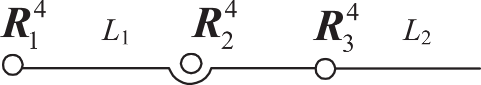
The relevant information of each link connected to the planar topology can be expressed by the following matrix

where Li
(1 ≤ i ≤ n) is the code of each rod in the kinematic chain; A is a (n − 1) × (n − 1) matrix that represents the geometric characteristics of the kinematic pairs between rods; J is a (n − 1) × (n − 1) matrix that represents the kinematic pairs connecting the rods, such as pair
The variation in the type of kinematic pair implies the removal of the original pair and the addition of the new pair. This process can be expressed as

The variation of the geometric type of the kinematic pair implies the removal of the original pair type and the addition of the new pair type, which can be expressed as
Suppose that

In the basic unit, the variation in the rod and the kinematic pair is the basis to realize the varied folding function of the kinematic chain. After obtaining the variation of each basic unit, these units must be combined into a complete kinematic chain, which is solved in the next section.
Fusion of basic unit
A complete kinematic chain is made up of a number of basic elements, which can be expressed as follows 19

where Ei and Ei +1 are the basic units of the kinematic chain, E is the kinematic chain, and ∪ is the connection and fusion between the basic units.
Analogous to cell fusion, the fusion between metamorphic units occurs between two units with fusion orientations and corresponding fusion parts. The fusion process is controllable and follows a particular rule.
A kinematic chain with a fusion tendency is composed of different rods and kinematic pairs that can be divided into the ones that participate in the fusion and the ones do not. Then, the kinematic chain can be expressed as 21

where
The fusion conditions of the metamorphic units:
If

where ∩ is the intersection between the basic units.
After analyzing and obtaining the variation and fusion modes of the basic unit, the research on the folding method of the multi-constrained quadrilateral suspension (MCQS) is presented. Several MCQS suspension planetary rovers with a folding function can be obtained by the operation of “Suspension Decomposition—Unit Variation—Unit Fusion—Screening Rejection.”
MCQS folding configuration
Taking into account the adaptability of the rugged terrain and obstacle negotiation performance, a multi-constrained quadrilateral lunar rover suspension configuration is proposed, as shown in Figure 5. The size ratio between the rods is scaled down from the actual size, and the kinematic pairs are

The MCQS diagram. MCQS: multi-constrained quadrilateral suspension.
As seen in Figure 5, the suspension configuration consists of several basic units. Therefore, the entire suspension can be decomposed into basic units. After the folding study, the fusion technology of the unit is used to assemble them into a whole, and the decomposition is shown in Figure 6.
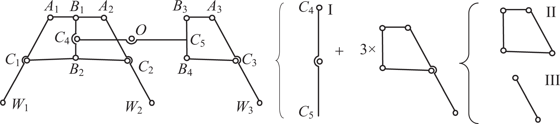
Basic units of the rover suspension.
It can be seen from Figure 6 that there are three basic units available for the study of folding, denoted as units I, II, and III. Figure 7 shows the three units more clearly, including 1 degree of freedom for the closed-chain four-bar unit and two open-link unit. The 2 × (3 ×) in Figure 6 indicate that there are 2 (3) identical units. After the three basic units of the MCQS are obtained, the rod number variation and kinematic pair variation are performed to obtain the basic units with different variants, and then use the unit fusion method to acquire the folding method with different suspensions.
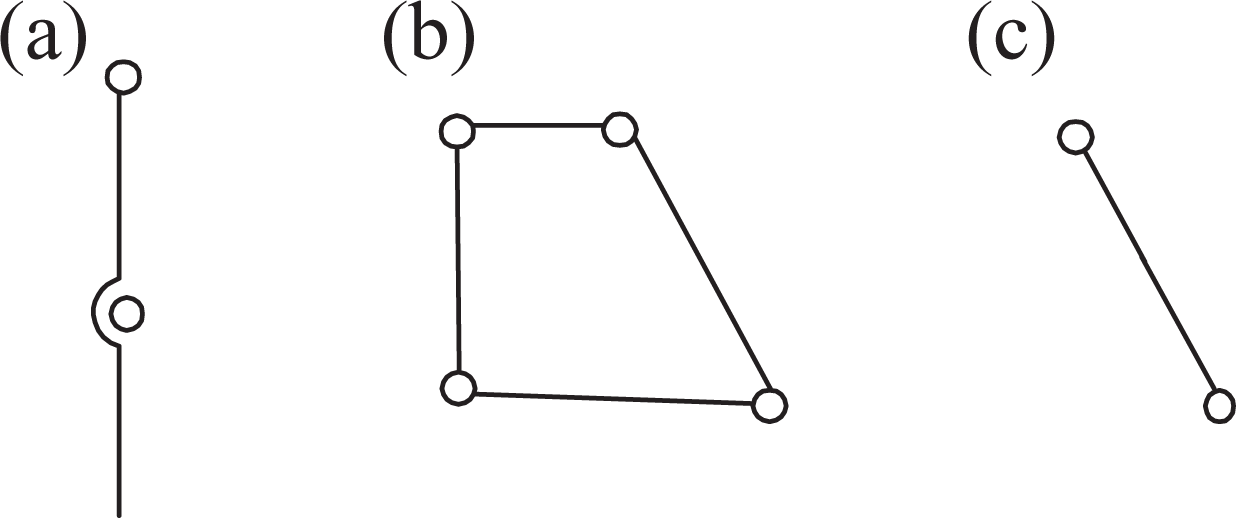
Four basic units after decomposition. (a) Unit I, (b) unit II, and (c) unit III.
Folding of unit I
Unit I has two
Increasing the rods of the unit
A default value of one rod is appropriate. Although theoretically more can be added, this will make the actual structure become complex, which is difficult to compute. At the same time, using

Kinematic pair transformation
Here, the transformation of the kinematic pair includes both the
Variation diagram of pairs in unit I.
The unit variation of the kinematic pair is the set of the variations of all pairs within the unit, as shown in equation (18), where

where 
Folding of unit II
As shown in Figure 7, unit II is a closed-chain four-bar unit. Compared with the decreased effect of the open-chain unit’s folding form by the size of the adjoining rods, the closed-chain unit is more constrained for folding, especially in the coordination of the size between adjacent rods. If not considered, the mechanism will be stuck or other forms of failure risk will occur in the folding process.
Folding of the basic configuration of unit II
The combination of the basic configuration of unit II is

where 
Configuration folding with adding kinematic pairs (rods) in unit II
Adding moderate kinematic pairs (rods) in the four-bar closed chain can avoid the rigidity problem from the configuration during movement after the kinematic pairs transform into the moving pair. To reduce the complexity of the structure, the structural mathematics for the adding process by allowing each rod to add one rod and one kinematic pair can be described with metamorphosis theory, which will not be explained here. The variation of four kinematic pairs after the additions is as follows


Folding of unit III
Unit III is a binary rod unit that is not constrained by the geometry of the carriage as seen in Figure 5, which means that unit III has a larger folding selection space than units I and II. Because unit III has only one rod, the folding performance is limited. Therefore, one kinematic pair is added first, and then the variation of the added kinematic pair is performed, where

Combining Figure 5,
The folding combination of unit III is

MCQS folding scheme
According to the structural and functional constraints of the MCQS, the basic unit folding combinations that can be used for the unit fusion are


Units I, II, and III participate in the fusion process of the basic units into the suspension, as shown in Figure 5. The folding scheme of the multi-constrained quadrilateral composite suspension after the fusion is shown in Figure 9 (the constraining spring is not shown).

Folding suspension scheme of multi-constrained rover.
The suspension comprises a plurality of repeating units, such as three unit Is and three unit IIIs. However, the repeating units are not necessarily in the same folding manner. With the aim of ensuring that the volume of the folded suspension is minimized when the individual units in the repeating unit are folded according to the folding combination.
Comparison of the schemes: According to the constraint that the suspension should be completely inside the left and right side of the carriage after being folded in the length direction, schemes 2, 3, 7, 13, and 15 (which are beyond the left and right side) are excluded. According to the standard that the folded suspension should allow the rover to move, schemes 1, 12, and 14 are excluded (when the blue unit of the scheme (1) is folded upwards, the folded suspension will exceed the left and right edges of the carriage). Although schemes 4, 5, and 9 can realize the movement of rover with a folded suspension, the folding diagram shows that wheels 1 and 2 are on the ground and wheel 3 is suspended, which will lead to instability of the carriage on the right side and touch the ramp or ground when the rover moves from the ramp of the lander to the ground, to affect the movement of the rover. Overall, the reliability of the movement after folding cannot be guaranteed. Therefore, schemes 4, 5, and 9 should be excluded.
Table 2 compares the remaining four schemes 6, 8, 10, and 11. It can be seen from the table that if only one folding scheme can be selected, scheme 6 has a good folding and unfolding performance and can be used as the final folding scheme of multi-constrained quadrilateral combined suspension.
Comparison among schemes 6, 8, 10, and 11.

Experimental research on moving mechanism of rover with MCQS retractable suspension
Figure 10(a) is a schematic diagram of a one-side suspension, where two parts of the suspension are respectively connected to the rail connecting plate and the slider connecting plate in the guide rail slide section. In Figure 10(b), the rail connection plates are respectively connected with the guide rail, the differential connecting block, connecting block 1, and the guide pin socket, wherein the differential connection block is consolidated with the output shaft of the differential and the connection block 1 is consolidated with the left portion of the suspension. The slider connecting plate is consolidated with two sliders and connecting block 2, in which connecting block 2 is consolidated with the right part of the suspension. In the figure, the guide pin holder is provided with a spring and a conical pin, which forms a locking mechanism together with the slider connecting plate. There is a tapered through hole in the slide plate, which has the same taper as the cone pin. The pin under the action of the spring is inserted into the pin hole to complete the lock on the rail slider position.

Single suspension and guide rail–slider. (a) Structural diagram of single suspension. (b) 3-D structural diagram of guide rail and slider.
Experiment on folding function
The folding function of the rover is primarily realized by a reduction in the size of length direction and the height direction. The change in the length dimension being the most obvious, and the contribution of the width dimension to the folding function is negligible. The foldable rover is designed to have a fold ratio of less than or equal to 0.6 to take up less space when launching and to reduce the overall launch costs. After the design and manufacture of the rover, the length and height of the rover when unfolded and folded are measured, as shown in Figure 11.

Dimensions of the MCQS rover under unfolded and folded configurations. (a) Unfolded configuration, (b) folded configuration, (c) the length of the unfolded rover, (d) the length of the folded rover, (e) the height of the unfolded rover, and (f) the height of the folded rover. MCQS: multi-constrained quadrilateral suspension.
The left and right column of the figure show the physical map of the unfolded and folded rover, respectively. The length and height dimensions of the rover are 1500 and 770 mm, respectively, and the size becomes 990 and 655 mm, respectively, after unfolding and locking. The folding ratio of the rover can be obtained by measured data.
The experimental data show that the folding ratio is 0.56 < 0.6, and the deviation is 5.3%, which meets the design requirements. By folding, the internal space of the rocket that is occupied by the rover can be reduced during launching. At the same time, some of the rods folded together can also improve the overall rigidity and natural frequency of the rover, to improve its safety and reliability.
Experiment on unfolding function
The planetary rover needs a high unfolding reliability. If the unfolding process cannot be completed by the rover body itself, the entire exploration task will be affected. As shown in Figure 12(a), the unfolding process of the rover is simulated, and the suspension is first folded in the laboratory. When the rover begins the unfolding process, first the motor of the front wheel is started to drive the rod connecting the wheels to rotate and drag the slider to slide along the guide rail to achieve an increase in the lengthwise dimension until the rotary rod and the guide rail are locked, as shown in Figure 12(b) to (d). After this, the front wheel motor stops rotating, and the rear wheel and the middle wheel motor start. The rear wheel turns counterclockwise and the middle wheel turns clockwise, so that the distance between the rear wheel and the intermediate wheel is pulled until the lever connecting the rear wheel and the intermediate wheel is rotated to the locked position and locked by the pin spring lock mechanism, as shown in Figure 12(e) to (f). The entire unfolding process has high reliability, and it can be ensured that the rover successfully performed the detection tasks.

Unfolding process of the MCQS rover. MCQS: multi-constrained quadrilateral suspension.
Conclusion
In this article, the variation mode of the basic unit in the kinematic chain mechanism is studied using the metamorphic mechanism theory. The variation of the basic unit has five types: the number of links, the number of kinematic pairs, the characteristics of the rods, the characteristics of the kinematic pairs, and the adjacency relationship. The mathematical models of these variants are deduced and obtained, and the concept of cell fusion was used to establish a mathematical model of the fusion of each basic unit into an entire mechanism. The MCQS suspension example is decomposed into three kinds of basic units, and the variation modes of these units are studied. The variation method of the suspension mechanism is determined, and the basic unit with different variants is fused into the whole suspension in permutations and combinations. A total of 15 kinds of folding schemes is obtained by screening and sorting, from which a suspension folding configuration is selected. The prototype of the rover with the MCQS suspension is developed, and the experimental folding and unfolding functions are carried out. The results show that the rover with MCQS is feasible.
Footnotes
Acknowledgement
The authors would also like to thank the 863 Project and the Program of Introducing Talents of Discipline to Universities.
Declaration of conflicting interests
The author(s) declared no potential conflicts of interest with respect to the research, authorship, and/or publication of this article.
Funding
The author(s) disclosed receipt of the following financial support for the research, authorship, and/or publication of this article: This work was financially supported by the 863 Project (no. 2008AA04Z202) and the Program of Introducing Talents of Discipline to Universities (no. B07018).