
Abstract
This article proposed a novel method for submarine hovering control implement by ballast tanks based on L1 adaptive theory. The ballast tanks are able to provide submerge/emerge force by let in/out ballast tank water, and therefore adjust submarine position and altitude when low-speed maneuver largely limits rudder effect. After formulate and analysis models of ballast tanks as well as submarine dynamic, control scheme is determined as cascaded controller system. L1 adaptive theory is adopted for outer loop control, to deal with the nonlinearity and uncertainties of model, as well as environmental disturbance in hovering condition for the first time. Robustness of control system is tested through simulations based on Simscape. Large impact force is exerted on submarine to simulate missile launching and test restoring ability of ballast tanks control. Simulation results demonstrated that the submarine is able to maneuver and response precisely, despite of sudden impact.
Keywords
Introduction
In the last decades, many researches have been addressed on the hovering control of underwater vehicle to explore the vehicle restoring ability under different environmental impact and often at extremely low speed. 1 Different hovering facilities equipped on underwater vehicles depending on the size and missions of vehicles, thus propose many tasks toward modeling and control of hovering system. 2
The expansion appliance of small-scaled underwater vehicle like Autonomous Underwater Vehicles (AUVs), leads to the automation of more complex tasks which has only been achieved by remote operated vehicles. 3 Hovering control is one of these tasks and is mostly accomplished by auxiliary thrusters. Palmer et al. proposed modeling method for through-body tunnel thruster, 4 during the transition from survey operation to low-speed maneuvering. 5 Zhao proposed three novel types of water hydraulic variable ballast system, which supports one or two low-cost means to control the flow rate of ballast water as to improve AUV hovering system performance. 6 Despite of this, internal buoyancy and balance control mechanisms also introduced in a low-cost highly maneuverable underwater vehicle capable of hovering and carrying dynamic payloads during a single mission, named Autonomous Modular Optical Underwater Robot (AMOUR, version 5), to achieve power efficient motions regardless of the payload size. 7
For manned submarine, steering effect can be insignificant at low speed like 2–4 knot; at the same time, it is not proper to use auxiliary thrusters as hovering facilities considering noise may occur. 8 The specially designed ballast tanks powered by hydraulic pump or high-pressure bottles usually used for submarine hovering. Located in the vicinity of the centroid of submarine, the ballast tanks mass control is also this article’s focus. For other novel submarine hovering method, Buck proposed a fluidic control system which controls the response of four fluidic “Hover Jets,” to counteract cyclic, suction, and missile reaction forces. 9
The hovering ballast tanks this article concerned are able to slightly modify the positioning difference due to sea density variation, pressure difference, and wave force. Moreover, when unexpected event or emergency occurs, ballast tanks quickly expel the water out to make submarine loss weight, thus can effectively enhance emergency rising maneuver. 10 Accurate hovering control of submarine position is also considered, for it is an invaluable tool as to safe swimmer delivery, 11 cover supply replacement and docking, and also military use. Hovering system should be capable of quick response with large directional forces to counteract extra forces exerted during rapid successive missile launchings despite all disturbance, thus to restore the submarine to required depth range. The exerted forces are divided into three different types: oscillatory, missile launch reaction, and suction force, which related to the existed sea state due to wave motion and their magnitudes. The “oscillatory forces” cause the submarine to heave, pitch, and roll. The reaction force, due to missile firing, tends to force the submarine move downward. This effect is dependent upon how many missiles are fired and their time intervals, usually extremely small, and the submarine should always be able to return to proper attitude after each missile launch in time for the next launching. The suction force is for all time acting in one direction, tending to move the submarine toward the surface, and it decreases with keel depth at a rate proportional to the square of the decrease of the oscillatory force.
Since hovering system is valuable for lowering noise, saving energy, and improving maneuvering of submarine, quick response and high-accuracy control are must. 12 However, traditionally hovering control is manually implemented rely on experience, and the accuracy is not guaranteed. 13 As robust control theory developed, it is crucial to introduce novel algorithm as to achieve high-accuracy hovering. 14 On the other hand, the designed Multiple inputs multiple outputs(MIMO) controller should be able to confront dynamic interactions, dynamic uncertainties, 15 and time-varying disturbance. 16 First proposed and developed by Hovakimyan and Cao, 17 L1 adaptive controller can be comprehended as improved model reference adaptive control scheme where the basic architecture is based on the internal model principle. 18 Tested in several applications such as flight control for aircraft, missiles, and spacecraft, L1 control is demonstrated with guaranteed robustness in the presence of fast adaptation. Lee and Singh have also applied the control theory for precise dive plane control of submarine, despite large uncertainties in parameters, nonlinearity, and perturbing force and moment. 19 Here in this article, cascaded control scheme is proposed and outer loop is based on L1 adaptive theory to accomplish hovering control of submarine. The control objective is to maintain original depth of submarine after extra force impact.
The rest of this article will be organized as follows: “Hovering system modeling” section gives mathematical model of hovering system, including ballast tank model and submarine dynamic model. “L1 adaptive hovering algorithm design” section presents a novel cascaded controller based on L1 adaptive theory. Several numerical simulations are conducted in Matlab and multidomain physical system Simscape to demonstrate the performance of proposed control scheme. The final section gives conclusions of the robustness of system.
Hovering system modeling
Hovering system design
On the reference of certain submarine prototype, the hovering system this article refers to is constructed by two ballast tanks: the stern tank and the bow tank, respectively, on both sides of the submarine along hull. By controlling water quantity in each ballast tank, extra force and moment exerted on the submarine, thus to adjust submarine position and altitude. The designed two tanks are of same configuration. Figure 1 shows the construction of each hovering tank.

Hovering tank construction.
The design of stern and bow ballast tanks is on the reference of Navantia-P650 design. 20,21 High-pressure air effuses from the air vessel through blowing valve to ballast water tank, squeezing the water out through flooding valve located at the bottom. Similarly, air in the ballast water tank will be expelled through venting valve when external water floods enter through flooding valve. Thus, the mass of submarine can be adjusted by controlling the mass of ballast water tank. The apertures of both blowing and venting valve are variable and to be regulated for flow of water. The configurations of the two tanks are listed in Table 1.
Configuration of ballast tanks.

Mathematical model
According to ITTC and SNAME reference system, the earth-fixed reference frame

In the above equations,
Define the mass, pressure, and absolute gas temperature as m, p, and T, with subscript t denoting which of ballast tank and subscript b denoting which of high-pressure bottle. Since the tank water greatly absorbs heat produced by high-speed air transfer, the air flow in the ballast tanks is assumed to be isothermal. However, the air flow process through nozzle throat and tube connection is seen as adiabatic, that is to assume no heat transfer with the surroundings. Gravitational force and extra heat caused by orifice net are also neglected. 24
Separate the air blowing process into two stages: supersonic stage is at the beginning of blowing when the tank pressure remains extremely high and subsonic stage follows the supersonic stage after air pressure rapidly drops in the ballast tank. The venting process is seen as an all through subsonic process. The mass variation of ballast tank air is derived as follow. For complete deduction, the study by Chen et al. is referred. 25

In the above equations, sB and sV are the grade of aperture of blowing and venting valve to be controlled. R is the specific gas constant, and pe denotes the exit pressure which can be regarded equal to atmospheric pressure. Here also taking the discharged coefficient Cd into consideration to count for the loss of effective area caused by orifice shape. 26
To prevent zero flow which leads to numerical solver difficulties, when pressure difference of tank and bottle is extremely small

Since the maneuver speed of hovering is extremely small, static Bernoulli equations can be applied to the system
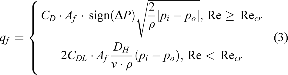
where pi and po, respectively, denotes water pressure that inside and outside the flood port and is calculated as


For the rest of parameters, patm denotes atmospheric pressure, zf and xf are the coordinates of flood port, readers may also referred to the study by Chen et al. 25 to get more specific deduction. For regular shape ballast tank, solve the following derivative equations to obtain the current water column height

The controlled mass variation of each hovering tank is finally derived as

where h0 and mt0 is the initial water column height and air mass in the tank. Substitute the above equation in equation (1), the mathematical model of hovering system is then completed.
L1 adaptive hovering algorithm design
Control schematic design for hovering system
The aim of the controller is to adjust submarine position to original depth and attitude when disturbance occurs. The control system is designed as cascaded type. The outer loop outputs desired water level in each ballast tanks depending on computing the given depth and pitch angle errors. L1 adaptive algorithm is applied in this control loop. The inner loop, however, is to follow the output of outer loop, that is to calculate appropriate grade of aperture of each blowing/venting valve. This inner control loop is based on PD controller. The control scheme of hovering control system is shown in Figure 2 above.

Submarine hovering control scheme.
L1 control algorithm design
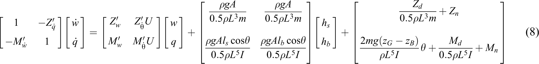
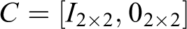
In this section, L1 adaptive control theory is employed to the outer loop control. Firstly, derivate (1) to obtain state space equations, which can be written as follows
Define


Since

Considering

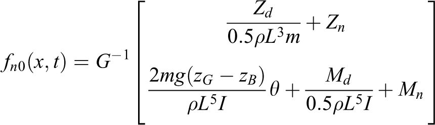
The above approximation is made on the fact that pitch angle is able to be limited extremely small value. Therefore, a state variable representation of submarine hovering is derived


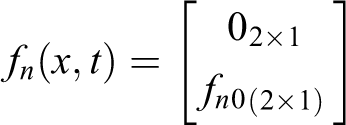
Notice that fn represent nonlinear and unmodeled factors, along with time-varying disturbance.
For L1 adaptive control, the control input is divided into two parts
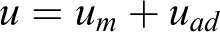
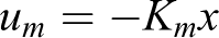
Here, um defines the feedback control signal related to dynamic characteristics and uad defines the adaptive control signal. By considering the uncertainties produced by ballast tanks, an uncertainty matrix can be defined as follows

Apply the above equations to equation (11) to obtain


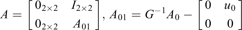
Define Am as a Hurwitz matrix of the form

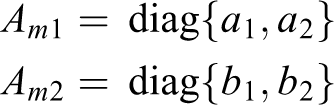
The static feedback gain matrix is then solved, and therefore should be designed as

The block diagram representation of typical L1 adaptive controller is shown in Figure 3.

L1 adaptive controller diagram.
Here, the L1 control system includes three segments: a state predictor, an adaptation law, and a control law. Assume that system disturbance, nonlinear hydrodynamics, and the unmodeled function g(x, t) are bounded. For some continuous input uad, there exists continuous bounded vector function

Apply the above equations in equation (12), to obtain semi-linear equivalent system equation

The state predictor is then deduced in the following form

Here,

Here,
Deduction of the adaptation law is based on the Lyapunov analysis. Here, select a quadratic positive definite Lyapunov function of the form

where Γ > 0 is the adaptation gain, P > 0 is the unique solution of Lyapunov equation
Derivate W along the above Lyapunov function at the same time applies state prediction dynamics of equation (16)

Choose adaptation law as

Projection operator is introduced to prevent parameter drifting in the scheme, which is defined for adaptation law as
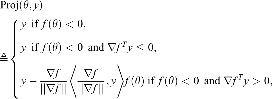
where fθ is a smooth convex function defined as
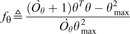
Here, θmax is the norm bound imposed on the vector θ, and εθ > 0 is the projection tolerance bound one can choose.
The estimated parameters in the above equation are then limited within expected bounds, and one can achieve fast adaptation by tuning the adaptation gain Γ.
The control law is finally selected as

Here, s denotes the Laplace transform operator and

kg, kf, and D(s) are 2 × 2 matrices, where kg can be solved as
Simulation
In this section, several simulations are conducted to simulate submarine maneuvers in diving plane. The first one is for fast diving of submarine using only the two hovering tanks. Based on the adjusting capability shown in the first simulation, sudden impact force and moment are given, respectively, on the submarine in the two later simulations. The simulations are conducted in Matlab, and multidomain physical system “Simscape” is adopted as useful tool for the modeling of hovering system.
Initial with neural pitch angle, and the surge speed is fixed at 3 knot, the submarine is first required to dive from 100 to 200 ft. It can be seen in the following pictures that the submarine steadily dives to the objective depth within 40 s, and without overshoot. Despite of this, the estimated parameters quickly converged within 10 s to some constant value. Figures 4 to 9 are some simulation results for fast diving, and Figure 4 shows the depth variation of the submarine. Figure 5 is the status estimations converging to zero. Figure 6 compares the estimation of three parameters. Figures 7 to 8 gives the water level of two tanks. Figure 9 is the control signal of blowing/venting valves.

Depth trajectory curve of submarine-fast diving.
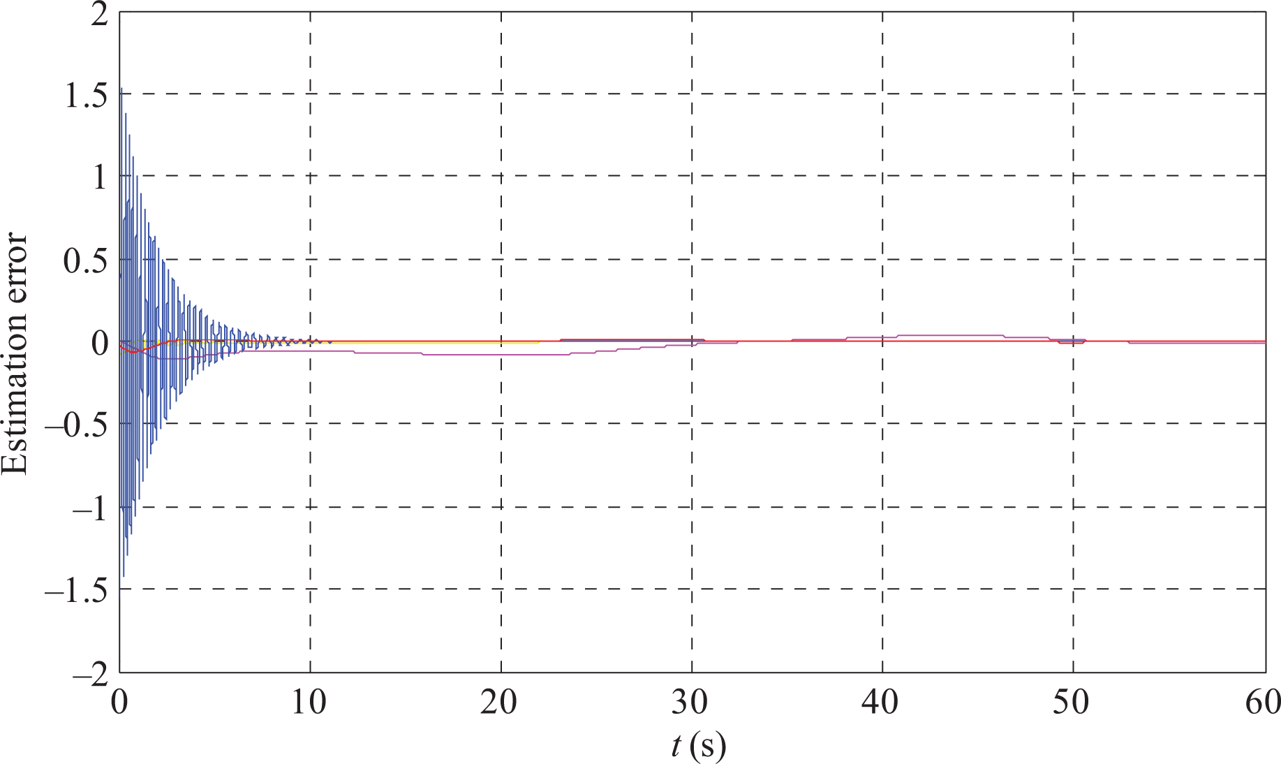
Status estimation errors-fast diving.

Parameter estimation-fast diving.

Water level variation of bow tank-fast diving.

Water level variation of stern tank-fast diving.
Control signal: grade of aperture of blowing and venting valve of each tank-fast diving.
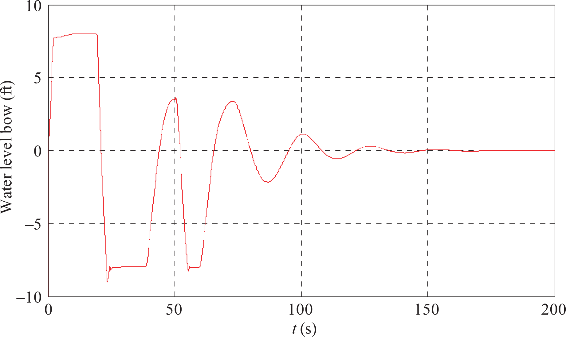
To simulate sudden disturbance force exerted on submarine, and thus to verify the robustness while emergency occurs, or while accomplish military missions, firstly, a 106 lb vertical force is inserted on submarine center at 50 s from simulation begins for 1 s duration. Initiating at 200 ft depth, the submarine is required to restore former position. Figures 10 to 15 are the corresponding simulation results.

Depth restoring curve of submarine-force disturbance.

Status estimation errors-force disturbance.
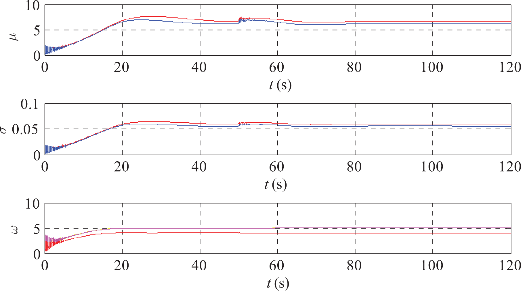
Parameter estimation-force disturbance.

Water level variation of bow tank-force disturbance.

Water level variation of stern tank-force disturbance.

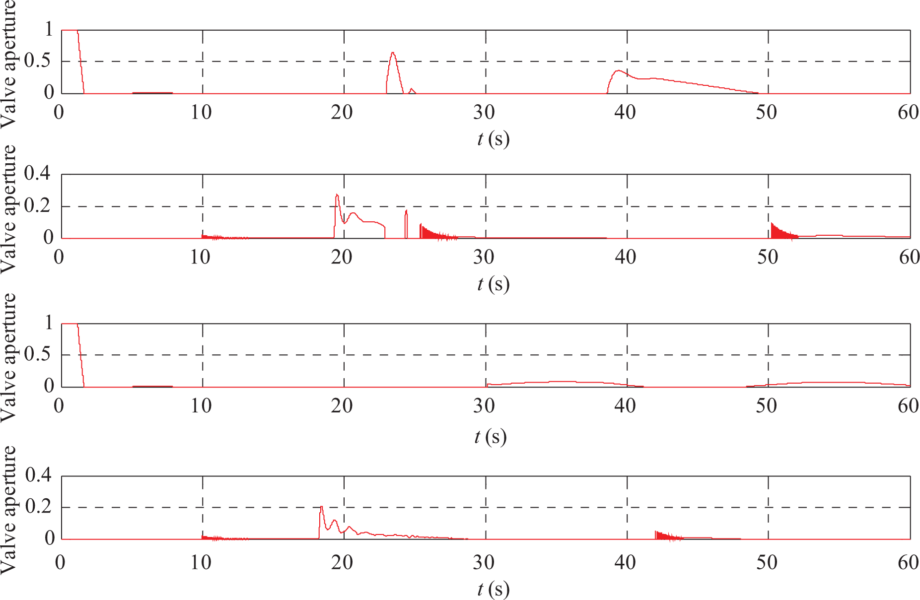
Control signal: grade of aperture of blowing and venting valve of each tank-force disturbance.
It can be seen from Figures 10 to 15 that the submarine is able to restore to initial depth within 20 s. However, the control signal is presented with tolerable amount of high frequency and is acceptable for appliance.
Separately, a certain disturbance moment of 108 lb ⋅ m is also exerted on the submarine to observe pitch angle variation while controlling water tanks. Figures 16 to 21 are the corresponding simulation results.

Pitch angle of submarine-moment disturbance.

Status estimation errors-moment disturbance.

Parameter estimation-moment disturbance.
Water level variation of bow tank-moment disturbance.

Water level variation of stern tank-moment disturbance.

Control signal: grade of aperture of blowing and venting valve of each tank-moment disturbance.
Shown in Figures 16 to 20, the disturbance moment is exerted at 50 s from simulation begins and lasts for 1 s too. The pitch angle is able to stabilize within 0.3° and is converged to some small amount around zero. Although the robustness of L1 algorithm is proved to be satisfying, the output jitter of controller is not negligible. Considering high-pressure air is limited at submarine, air-consuming speed should be restricted at low level. Therefore, the controller high-frequency output should be limited.
To summarize, apply L1 adaptive theory on controlling hovering tanks, the maneuverability and robustness of submarine at extremely low speed is guaranteed. Especially when large impact force exerted, the submarine is able to restore itself to original position and altitude in a short time. However, the high-frequency fluctuates of control signal still exist and should be eliminated.
Conclusions
This article presented a novel control scheme based on L1 adaptive theory, aiming at hovering control of submarine. On the foundation of previous work, the modeling of hovering tanks is proposed first, along with dynamic model of submarine. Control scheme is then designed as cascaded type composed by outer loop system based on L1 control theory and inner loop system based on PD control theory. In this way, the inner loop is able to provide valve aperture signal, to track the water level outer loop demands, and then to eliminate depth and pitch angle deviation. The robustness of the proposed control scheme is then demonstrated through a set of simulations. The submarine is able to accomplish rapid diving and quick self-adjustment while disturbance and large sudden impact occurs.
Footnotes
Declaration of conflicting interests
The author(s) declared no potential conflicts of interest with respect to the research, authorship, and/or publication of this article.
Funding
The author(s) received no financial support for the research, authorship, and/or publication of this article.