
Abstract
The aim of this research is to examine the different control strategies for the unmanned aerial vehicles (UAV). The control task is formulated as an angular stabilization of the four rotor platform, and also as a tracking problem of chosen state variables. The PID algorithm has been considered in three structures in respect of the optimal control signal applied to the actuators. For better performance of the quadrotor in hover mode the cascade control system has been proposed. The simulation results of attitude control with different PID controller architectures are presented, and confirm the effectiveness of the proposed control structure and theoretical expectations. Moreover, the design and the practical realization of the control architecture on the experimental aerial vehicle are described. The fast prototyping method together with Matlab/Simulink software and DAQ hardware are used for both evolution and validation of control algorithms. The capacity of the attitude stabilization system is important in the development process of more advanced functionality of autonomous flying vehicles; therefore it needs to be highlighted and taken into careful consideration.
1. Introduction
Small autonomous flying systems are highly desirable in many areas of expertise, such as security, safety and natural risk management, environmental protection, management of large infrastructures, management of ground installations, agriculture and also film production [1], [2]. Among the several kinds of mini and micro unmanned aerial vehicles (MUAVs), the most common are rotary-wing aircraft. Their main advantage is the capability of hovering and taking-off or landing in small areas. A quadrotor, one such UAV with four vertical rotors, is a highly operative flying craft (Figure 1).
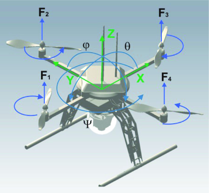
Quad-thrust aerial robot.
It has been widely developed by many universities and commercial companies such as Draganflyer, X3D-BL, and Xaircraft [3]. The high manoeuvrability and compactness of this platform make it suitable for indoor use, as well as for outdoor applications. However, a quadrotor is an unstable platform and impossible to fly in a full open loop system. Therefore, advanced embedded systems are widely used for controlling these platforms. The dynamics of a flying vehicle are more complex than for ground robots, so that even hovering becomes a non-trivial task. Thus, the control of a nonlinear plant is a problem in both practical and theoretical terms. The attitude controller is an important feature since it allows the vehicle to maintain a desired orientation, and hence prevents the quadrotor from crashing when the pilot performs the desired manoeuvres. Improved performance in the new generation of VTOL vehicles is possible through derivation and implementation of specific control techniques incorporating limitations related to sensors and actuators. The most well-known approach to the decoupling problem is based on the Non-linear Inverse Dynamics (NID) method, which can be used if the parameters of the plant model and external disturbances are exactly known. Usually, information about systems in real practical tasks is incomplete. In this case adaptive control methods or control systems with sliding modes [2], [4] may be used as solutions. An algorithmic solution to the problem of incomplete information about varying parameters of the plant and unknown external disturbances is the application of the Dynamic Contraction Method (DCM) [5] applied in [6]. But the most significant problems of these approaches in real applications are the high order of the controller equations and the influence of measurement noise on control quality. Approximations of higher derivatives amplify the measurement noise and cause abrupt changes of control signal. Therefore, in this article the different structures of PID controllers, which can reduce the adverse effects, are considered.
The main aim of this research is to examine the effectiveness of a designed attitude control system for the quadrotor in the cascade control system with different types of PID controllers [7], [8], which are used in practical implementation on the target hardware platform.
The paper is organized as follows. First, a mathematical description of the quadrotor nonlinear model is introduced. The next part presents a general structure of a cascade control system, and investigation of three types of PID controllers with modified loop structure. This section includes the schemes and descriptions of PID controller types A, B and C. The next chapter shows the results of simulations in two sections: first - inner loop control with all types of PID controllers; second - performed in the cascade control system. The penultimate part is about the experimental test bed used for control structure implementation and validation. Some technical aspects are also presented together with the experimental results. Finally, the conclusions are briefly discussed in the last chapter.
2. Quadrotor Model
The aerial vehicle consists of a rigid cross frame equipped with four rotors as shown in Figure 1. The two pairs of propellers (1,3) and (2,4) turn in opposite directions. By varying the rotor speed, the lift force can be changed and motion created. Thus, increasing or decreasing the four propellers' speeds together generates vertical motion. Changing the 2 and 4 propellers' speed conversely produces roll rotation coupled with lateral motion. Pitch rotation and the longitudinal motion result from 1 and 3 propellers' speed being conversely modified. Yaw rotation is a result of the difference in the counter-torque between each pair of propellers [9].
2.1 Rigid Body Model
The quadrotor is a six-degrees-of-freedom system defined with 12 states. The following state and control vectors are adopted:


where ui - control input of motor, i = 1,2,3,4- motor number.
Six out of 12 states govern the attitude of the system. These include the Euler angles (φ,θ,Ψ) and angular rates around the three orthogonal body axes. The other six states determine the position (x,y,z) and linear velocities of the centre of quadrotor mass with respect to a fixed reference frame.
The dynamic model is derived using Euler-Lagrange formalism under the following assumptions:
the frame structure is rigid,
the structure is symmetrical,
the centre of gravity (CoG) and the body fixed frame origin are assumed to coincide,
the propellers are rigid,
thrust and drag are proportional to the square of the propeller speed.
Taking these into account, the quadrotor mathematical model can be divided into two subsystems (propulsion and rigid body model) as depicted in Figure 2.

Block diagram of system dynamics.
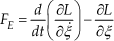
Using the Lagrangian method and the general form of Langrangian equations of motion [9–12]:


where: L is Lagrangian, TK is kinetic energy, V is potential energy, q=[x,y,z,φ,θ,Ψ]T is a vector of generalized coordinates, F = (FE, T) are generalized forces FE and moments T applied to the quadrotor due to the control inputs.
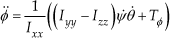
For translational motion the Lagrange equation has a form:
where: ξ=[x,y,z] T - position coordinates,

Ωi - rotor speed
b - thrust factor
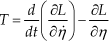
Accordingly, the Lagrange equation for rotary motion is:
where:
η=[φ,θ,Ψ] T - Euler angles

l- distance between propeller centre and CoG, Jr - rotor inertia, d- drag factor.
The above torque equations (Tφ,Tθ,TΨ) consist of the difference in the action of the thrust forces for each pair, and the gyroscopic effect.
Finally, the quadrotor dynamic model with x, y, z motions as a consequence of a pitch, roll and yaw rotation is as follows:
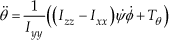
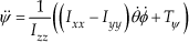


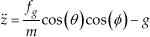
where:
Ixx, Iyy, Izz - inertia moments.
2.2 Propulsion System
In general, rotary-wing aircraft have no lifting surface. All the thrust force is generated thanks to the propulsion system, which in most cases consists of the brushless DC motor and a propeller. This motor is commonly known as an electronically commutated motor, which is in fact a synchronous motor [13]. Brushless motors offer greater efficiency than brushed DC motors, including more torque per weight, more torque per watt, etc. [14]. These features are also a reason why these motors are used as a direct drive. In spite of the complexity of the electronic commutation process, such motors can be modelled in a conventional way. An equivalent schema for the brushless DC motor together with the propeller is presented in Figure 3.

Equivalent model of propulsion system.
The main limitations of the motor model compared to the real motor are listed below.
Remark 1. The magnetic circuit is linear, which is an approximation because of some flux dispersion inside the motor.
Remark 2. Mechanical friction is only linear and is a function of the motor velocity, namely viscous friction.
Brushless DC motor dynamics can be modelled as follows. Um is a voltage applied to the motor and im is an armature current. Motor winding has resistance Rm and inductance Lm. The back electromotive force generated by the rotor is denoted by em and is a ratio of shaft velocity Ω. Motor torque Tm is proportional to the armature current im. The load has an opposing torque To.
From basic physics principles the electrical equation of the system has the following form:

The mechanical equation can be expressed as follows:

where the whole rotor and propeller inertia (Jm, Jr) is reduced to the inertia of the motor shaft J, and B is a constant that represents the viscous friction coefficient.
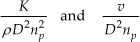
The torque produced by the motor drives the propeller with the same angular velocity because of the direct connection. The principle of the thrust generation process can be fully explained by the approach commonly referred to as momentum theory. In order to obtain better performance, simple momentum theory can be combined with blade element theory, which gives more adequate results [15]. The performance of the propeller can be expressed in terms of nondimensional coefficients. Let us consider the airscrew diameter D, revolving at np revolutions per second, driven by the torque Tm. Let us also denote that air characteristics are defined by density p, kinematic viscosity v, modulus of bulk elasticity K and the forward velocity of the propeller V. The relationship between the angular velocity and the thrust is given in the following form [15]:

The thrust coefficient CT is a propeller parameter and primarily depends on the λ ratio given as:

It is also a function of the Mach and Reynolds numbers, respectively expressed by the following terms:
Finally, the propulsion system is modelled as a series connection of a linear first order dynamic element and nonlinear second degree polynomial for the propeller revolutions. This is acceptable when we consider a hover mode of the quadrotor. Here, the static thrust calculation can be applied (Figure 4).

Static characteristic of propulsion system.
The quadrotor parameters are listed in Table 1.
Quadrotor parameters.

3. Control scheme
In control applications, the rejection of external disturbances and performance improvement are major concerns. In order to fulfil such requirements, the implementation of a cascade control system can be considered (Figure 5). Basically, in a cascade control schema the plant has one input and two or more outputs [7]. This requires an additional sensor to be employed so that the fast dynamics can be measured. The primary controller and the primary dynamics are components of the outer loop. The inner loop is also a part of the outer loop, since the primary controller calculates the set point for the secondary controller loop. Furthermore, the inner loop represents the fast dynamics, whereas the outer should be significantly slower (with respect to the inner loop). This assumption allows interaction that can occur between the loops to be restrained, improving stability. Therefore, a higher gain in the inner loop can be adopted. An additional advantage is that the plant nonlinearities are handled by the controller in the inner loop, and exert no meaningful influence on the outer loop [8].
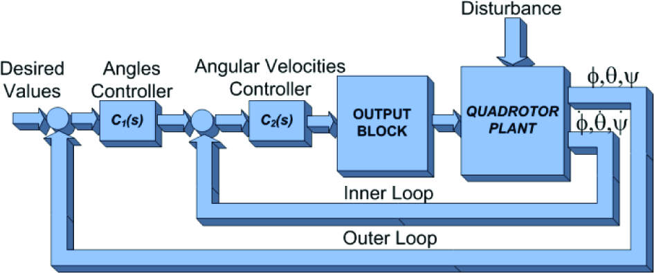
Cascade control system for quadrotor.
In this work the cascade control structure is proposed as a solution to control tasks formulated as angular stabilization. The angular velocities of the rotating platform are additional measurements that can be used in the inner loop. In this case, there is no need to assemble any extra sensors, and the AHRS (Attitude and Heading Reference Signal) therefore provides not only angles but also other raw data, such as accelerations, angular velocities and gravitational field strength. The outer loop is based on the Euler angles and the measurements are calculated from the combination of the accelerometers, gyroscopes and magnetometers. The cascade control loop for the quadrotor vehicle is shown in Figure 5. In both loops three types of PID controllers are considered.
3.1 PID Controller - type A
In control theory the ideal PID controller in a parallel structure is represented in the continuous time domain as follows:

where:
Kp- proportional gain,
Ki- integral gain,
Kd-derivative gain.
A block diagram that illustrates the given controller structure is shown in Figure 6.
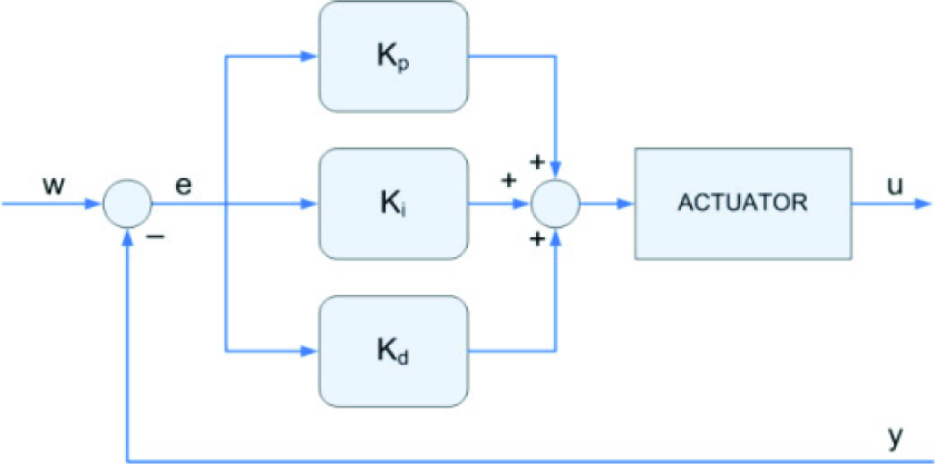
PID Controller - type A.
The problem with conventional PID controllers is their reaction to a step change of the input signal, which produces an impulse function in the controller action. There are two sources of the violent controller reaction - the proportional term and the derivative term. Therefore, there are two PID controller structures that can avoid this issue. In the literature they are given different names [7, 8]: type B and type C; derivative-of-output controller and set-point-on-I-only controller; PI-D and I-PD controllers. The main idea of the modified structures is to move either the derivative part or both the derivative and proportional part from the main path to the feedback path. This is so that they are not directly subjected by the jump of set value, while their influence on the control reaction is preserved, since the change in set point will still be transferred by the remaining terms.
3.2 PID Controller - type B
It is more suitable in practical implementation to use “derivative of output controller form”. The equation of the type B controller is:

A block diagram that illustrates the given controller structure is shown in Figure 7.

PID Controller - type B.
If PI-D structure is used, discontinuity in r(t) will still be transferred through proportional into control signal, but it will not have as strong an effect as if it was amplified by derivative element.
3.3 PID Controller - type C
This structure is not as common as the PI-D structure, but it has certain advantages. The control law for this structure is given as:

A block diagram for the type C controller is shown in Figure 8.

PID Controller - type C.
With this structure the transfer of reference value discontinuities to control signal is completely avoided. Control signal shows less sudden changes than with other structures.
3.4 Output block
The main goal of the output block in Figure 5 is to accomplish an algorithm of quadrotor control, and provides decoupling of control channels in steady state. The control inputs from cascade controllers, about each axis uφ,uθ,uΨ, are therefore combined to generate the control inputs u1 through u4, for motors 1 to 4. The general system structure is presented in Figure 9.

Output block structure.
4. Simulation results
In this section, we present the results of simulations conducted to evaluate the performance of the designed attitude control system in the cascade structure with different types of PID controllers. The presented simulations show transition with predefined dynamics from one steady-state flight to another. In the design process we consider three types of PID controllers (type A, B, C), optimizing the parameters in view of the assumed reference model. To evaluate the quality of control in the tracking of the reference model, and in particular the feasibility of the control with regard to practical aspects, were taken into account.
The entire MIMO control system consists of three cascade control channels with two PID controllers each. Feedback data for the regulators include six variables: Euler angles φ,θ,Ψ (outer loop) and angular velocities

where φ0(t),θ0(t), Ψ0(t) are the desired values of the considered variables.
In view of the complexity and multidimensionality of the considered problem, only the results from 9 pitch control channel are presented.
The tuning of the cascade controller parameters was divided into two steps. First, the inner loop controller was tuned based on the assumed reference model. The desired dynamics were determined by the following transfer function:
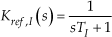
whereTI= 0.25 [s].
At this stage of design we considered three structures of PID controller: type A, type B (PI-D), and type C (I-PD).
In this case the accuracy requirements for the system are formulated in the form of two performance indices related to the time responses of the system. Therefore, the following quadratic integral index was introduced for the tracking performance:
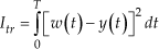
The second index determines the effort of control signal and is defined as follows:

Numerical results are shown in Table 2.
Performance Indices.

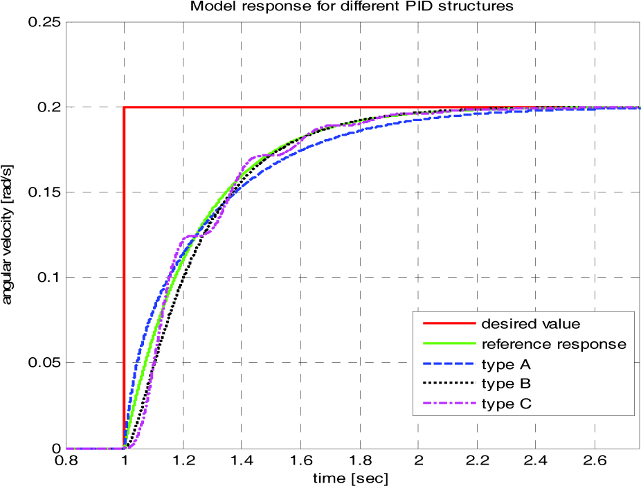
Time history of angular velocity.
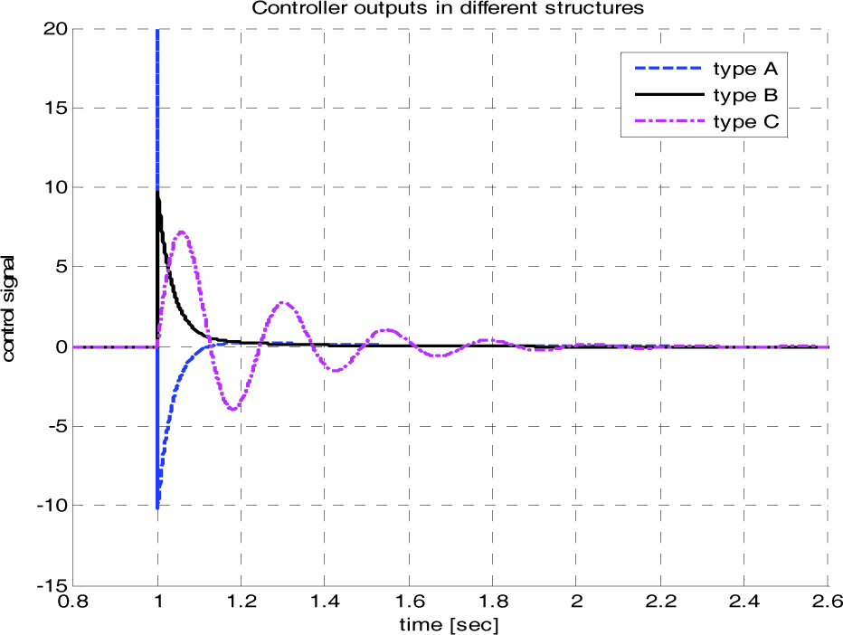
Time history of control signal uθ.
Remark 1: The relative order of the inner loop with PID controller is equal to one.
Remark 2: Based on remark 1 the reference model is provided by the first order inertia system (22).
Remark 3: Gradient descent method allows tuning of the controller parameters to obtain satisfactory reference model tracking results in all structures (Table 2).
Remark 4: However, the index of control signal effort in particular types of PID controllers indicates significant differences.
Remark 5: In terms of practical implementation, type A seems not to be acceptable (value=2047). On the basis of the presented findings, the most common structure is type B; therefore, this will be used in the next step as the best possible solution.
In the second step the outer loop controller is tuned based on the following assumed reference model:
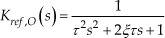
where: τ = 0.4- undamped resonance period, ξ=1-relative damping factor.
Remark 6: In respect of the slower outer loop dynamics, the reference model was determined as a second order differential equation (25).
Remark 7: Referring to remark 5, the advantages of the type B PID controller have been confirmed in a cascade control system.
Remark 8: In the case of PI controller the architectures A and B are equivalent.

Time history of pitch angle and angular velocities.
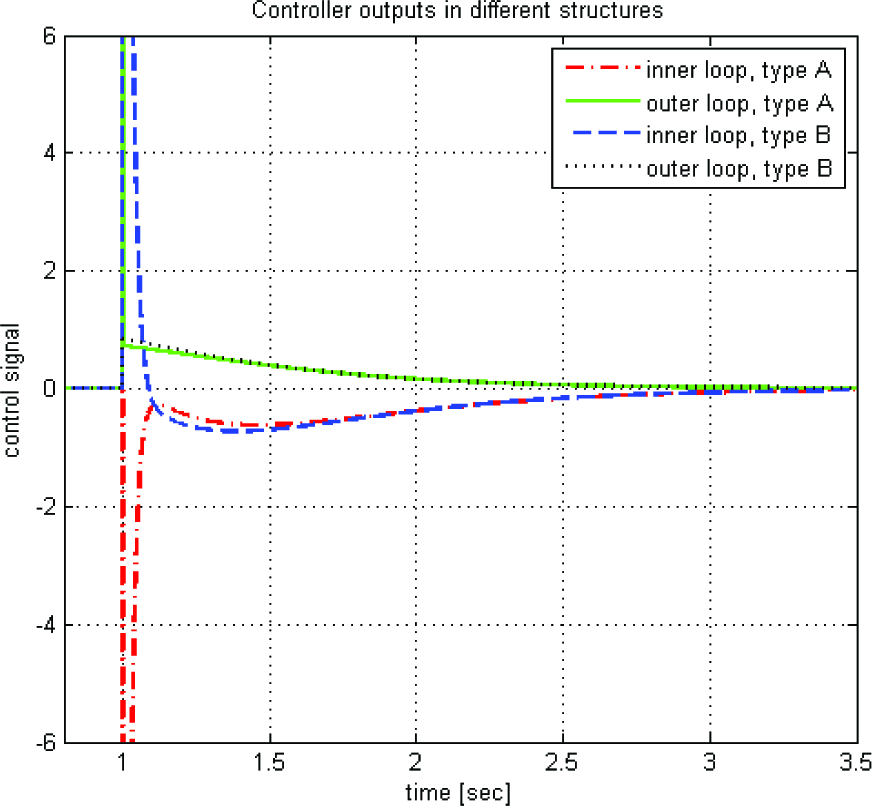
Controller signals.
5. Experimental verification
During experiments, a setup consisting of a modified Draganfly quadrotor airframe with propulsion system, AHRS, PC with I/O card and RC transmitter has been used (Figure 14).
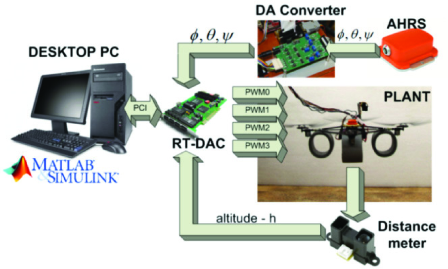
Quadrotor test bench.
The frame is composed of carbon tubes attached to a plastic hub, with propulsion systems at the other ends. The quadrotor has four propulsion systems, each composed of a brushless DC-motor driven by a PWM signal and a two-bladed propeller. In view of the mechanical vibrations that affect the measurement system, the airframe has been reinforced with carbon tubes. The AHRS sensor and electronic circuitry were added to the redesigned airframe. The miniature MTi Xsens AHRS estimates the 3D orientation data with a Kalman filter and gives the calibrated data of acceleration and angular velocity.
Experimental testing has been performed with a sampling frequency of 50Hz, using a stationary PC with I/O card RT-DAC4 as a Data Acquisition and Control Device. The Matlab and Simulink software in combination with Real-Time Workshop and RT-CON allows easy implementation of the control system in Simulink via block diagrams, with the possibility of real-time tuning of the controller parameters. This structure of experimental setup was used for a fast prototyping of the designed control system, as well as the attitude control system concept, in the hardware in the loop system.
In this section, we present the results of initial experiments conducted on the quadrotor to evaluate the performance of a designed attitude control system. Firstly, the simulation model of the quadrotor developed under the Matlab/Simulink software was taken into consideration. This gives a general idea of the flying platform's dynamics and behaviour. Proper choice of model parameters gives the starting values for the controller parameter tuning procedure on the real control object. The tests have proven that the quadrotor properly tracks changes in set points on all axes. The results are presented in Figure 15.
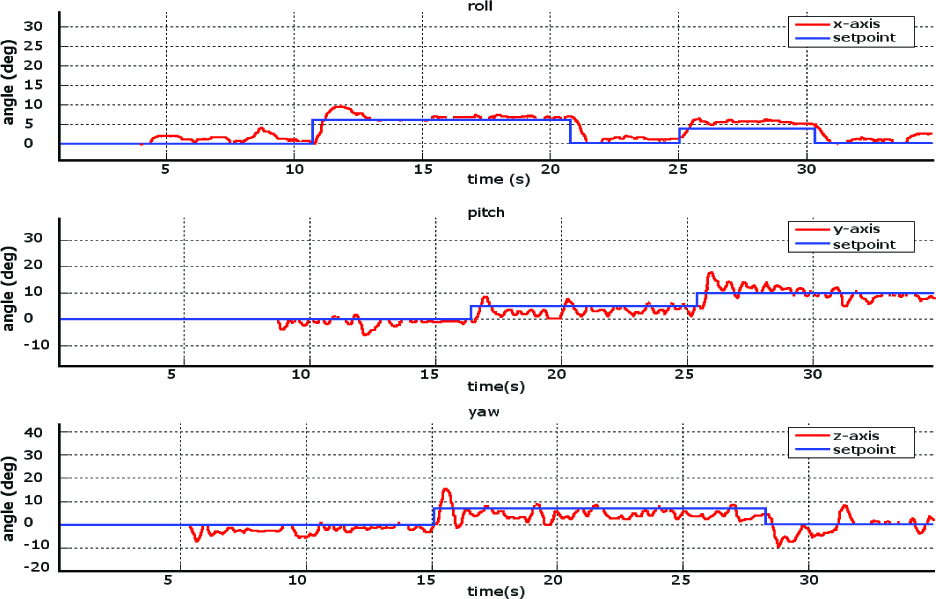
Tracking changes in set points.
6. Conclusion
In this paper, quadrotor dynamics are presented in detail together with the propulsion system. The designed control system consists of an angular stabilization system for the unmanned platform. The problem of different dimensions between inputs and outputs was solved by the MIMO PID controller and output block, which allow the control algorithm to be applied. The peculiarity of the attitude stabilization causes different approaches to the control problem to be considered. The main goal of this research is the evaluation of different types of PID algorithm in practical aspects of control systems design. Three architectures were presented and examined with respect to their best performance. All of the reviewed architectures of the controllers resulted in almost the same model output response time, but significantly different control signals. Taking into account the proposed control effort index, type B architecture is the most comprehensive choice.
The assumed reference models provide the time separation between fast and slow dynamics in the cascade system. The application of a cascade control structure allows the adaptation of the simple PID algorithm for controlling complex systems, such as the vertical take-off and landing of the vehicle. The proposed approach is an alternative solution to the advanced control algorithms, but requires an additional sensor to provide measurement of the inner control loop. However, for an unmanned aerial vehicle, such as a quadrotor, the cascade control architecture can be implemented without any extra sensing elements. The presented solution can be applied in both an indoor and outdoor environment.
The conducted simulations and analysis proved the ability of the designed cascade structure in controlling the orientation platform angles and providing the promising fundamentals for practical experiments with a physical plant. To examine the performance of the proposed control structure, additional tests on the quad-thrust aerial robot were conducted. The cascade PID control system was introduced together with the requirements and appropriate constraints for the system to validate such control algorithm applications in real conditions. According to the results of the research on the simulation model, an appropriate system for the quadrotor was developed in the form of a cascade PID and PD positional controllers of type B with filtered derivative terms, double integral windup protection and a limited set point changes ratio.
Footnotes
7. Acknowledgments
This work has been possible thanks to funds for science in 2010-2012 as development project No. OR00011811.