
Abstract
This article adopts a 2-UPS+UP (U, P, and S are universal joint, the prismatic joint, and sphere joint, respectively) parallel mechanism as the leg mechanism of the quadruped walking robot based on the bionic concept and the motion capacity of the leg mechanism. The article investigates the kinematics (including the leg mechanism and the whole mechanism), gait planning, control, and experiment in detail. The following tasks are conducted: (1) designing the whole mechanism and developing the kinematics equations for both the leg mechanism and the whole mechanism; (2) planning the trotting gait and designing the foot trajectory based on the robot characteristics and conducting the kinematics analysis; (3) building the control system of the robot using self-developed controllers and drivers and studying the compound position control strategy; and (4) conducting the experiments for validating the controller, the compound position control strategy, the trotting pace, carrying capacity, and human-carrying walking. The results confirm that the proposed human-carrying walking robot has good performance and it is also verified that the controller and the compound position control strategy are suitable.
Keywords
Introduction
Walking aids have been an attractive research topic for a number of years. 1 A human-carrying walking robot, which is a type of walking aids, can help elderly and the lower limb disabled people walk freely in the outside environment and on uneven ground.
The human-carrying walking robot is different from wheeled robots and ordinary legged robots. It not only needs to walk steadily using the leg mechanism as a supporting point 2,3 but also has to bear a total weight comprising both its own weight and the load. 4 These create higher requirements for the leg mechanism performance of the walking chair robot. At present, most of the human-carrying walking robots for elderly and the lower limb disabled people are implemented using the serial mechanism to be the walking chair’s leg mechanism, 5 –9 such as the i-foot robot, the Hubo FX-1 robot, and the Hyperion4 robot. Using the serial mechanism as a leg mechanism, the whole volume and weight of the robot are greater and the carrying capacity is smaller. For instance, the i-foot robot weights 200 kg and it can only carry a 60 kg person; Hubo FX-1 weights 150 kg and it can only sustain a 100 kg load. Compared with the serial mechanism, parallel mechanism (PM) can overcome the deficiencies of the serial mechanism and form a complementary relationship with the serial mechanism. 10 –12 For example, the WL-16RIV biped walking chair robot designed by Waseda University, Japan, weights 68 kg and can carry up to an 80 kg person. On the other hand, observing the animal motion systems (including human), it is noted that skeletal muscles are attached to the bones by tendons and arranged in a parallel way (shown in Figure 1). This parallel-link way of animal is similar to the PM. So PM is one of the better choices for the leg mechanism of a human-carrying walking robot.
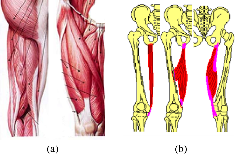
Human leg system. (a) Anatomic assembly. (b) Link diagram of muscle and skeletal.
Since the PM with limited-DOF (degrees of freedom) has the advantages being a simple mechanical structure with low cost for design, manufacturing, and control, the PM with less than 6-DOF is widely used. Analyzing the leg mechanism of the human-carrying walking robot, we conclude that it needs 3-DOF (swing back and forth, swing left and right, and lifting up and down). Considering manufacturing costs, the universal joint and the linear actuator could be purchased and each branch of PM includes these two kinematic pairs as soon as possible. Therefore, the mechanism configurations for meeting the motion and low-cost requirement are symmetrical 3-UPU PM, 13 3-PUU PM, 14 3-RPS PM, 15 and asymmetrical 2-UPS+UP PM, UPS+SPR+SP PM and UPS+UP+UPR PM. The 3-UPU PM is difficult to ensure that the axis of the two universal joints for each branch is parallel when the installation is finished. 16 As a leg mechanism, the arrangement of the prismatic joint for 3-PUU PM is difficult to achieve. If the 3-RPS PM is selected for the leg mechanism of the walking chair robot, then the walking chair robot may not move because of constraint forces coupling between branches. For asymmetrical UPS+SPR+SP PM and UPS+UP+UPR PM, it is difficult to realize a modular design and to low-cost manufacturing.
The manufacture cost of 2-UPS+UP PM is lower. For its UPS branch, there is no constraint on the moving platform, the motion of the whole asymmetrical PM is determined by the UP branch. 17 So we select 2-UPS+UP PM as the leg mechanism of the human-carrying walking robot.
Gait planning of the walking robot depends on the leg structure and the number of legs, for example, the eight-legged imitation crab robot, 18 the gecko-like robot, 19,20 the hexapod robot, 21 and the biped robot. 22 –24 For the same robot, the planned gait depends on the various states of motion such as free walking gait, 25 climbing stair gait, 26 turning gait, 27 and trotting gait 28 for the quadruped robot.
Compared with the general quadruped robot, the leg structure of the human-carrying walking robot studied in this article is different. To the best of the authors’ knowledge, there is little work available for its gait planning.
Generally, the gait of a quadruped robot can be divided into static walking gait and dynamic walking gait. Employing the static walking gait for a robot, the inertial forces are ignored. Using the dynamic walking gait, the inertial forces are considered. The static walking gait includes the crawl gait and the amble gait. The dynamic walking gait mainly includes the gallop gait, the trot gait, the bouncing gait, and the unilateral jogging gait.
Passenger safety is the most important requirement of the human-carrying walking robot. So the walking speed of the robot has to be limited to provide a comfortable transport for the passenger. Comparing the static and the dynamic walking gait and considering the structure of the walking robot, the trotting gait with a modification is selected as the motion gait of the walking robot.
The article is organized as follows. “Design of the whole mechanism” section describes design of the whole mechanism and establishes the coordinate system. In the section “Kinematics analysis of the walking robot,” kinematics for the parallel leg mechanism (PLM) and the whole mechanism are analyzed in detail. In the section “The foot trajectory and trotting gait planning,” based on kinematics, the trotting gait is planned and the foot trajectory is designed. In the section “Experiment research of the walking robot,” experiment researches for the leg mechanism and the whole walking robot are conducted.
Design of the whole mechanism
The prototype of the human-carrying walking robot is shown in Figure 2. The whole mechanism consists of a seat, a connection plate, four PLMs, and a control system. Among them, the seat, the connection plate, and the control system are collectively called the body mechanism.

Human-carrying walking robot.
The PLM consists of the upper platform, the lower platform, two UPS branches, and one UP branch. Joint S of the UPS branch is made up of one rotation joint and one universal joint (as shown in Figure 3(a)). According to the performance analysis of the walking robot 17 and the market information, the structural design parameters of the walking chair robot are defined as follows. The rotational range for each axis of the universal joint is –π/2 to π/2. Joint P is realized by the linear actuator and the range is from 441 mm to 741 mm. Both of the upper and lower platforms are equilateral triangles, and a and b are their sides, respectively. φ and ϕ are angles of the triangles for the upper platform and the lower platform, respectively. t 1 and t 2 are the thickness of the upper platform and the lower platform, respectively. d 1 is the distance between the connecting hole of connector 1 and the end face of the upper platform. d 2 is the distance between the center of universal joint and the connecting hole of universal joint. d 3 is the distance between the two connecting holes of connector 2. d 4 is the distance between the two connecting holes of connector 3. d 5 is the distance between the connecting hole of connector 4 and the end face of the lower platform. d 6 is the length of the rotation joint. The design values of these parameters are shown in Table 1 and the structure is shown in Figure 3(b) to (d).
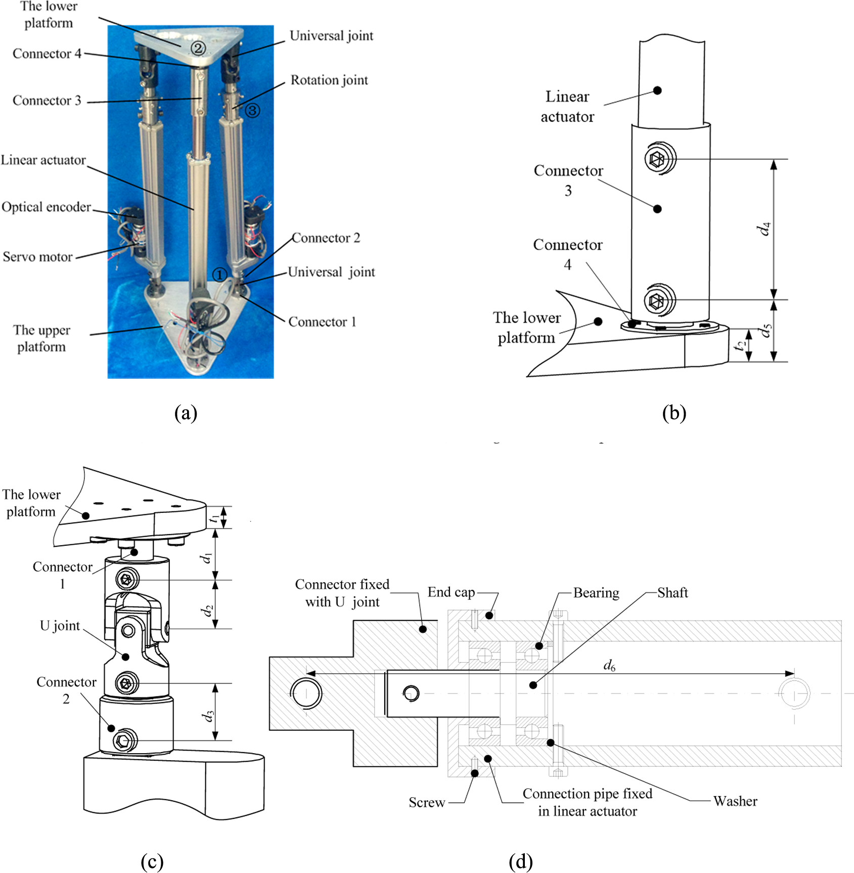
(a) 2-UPS+UP PM. (b) A larger version of position 2 in (a). (c) A larger version of position 3 in (a). (d) Internal structure of the rotation joint.
Design parameters for the leg mechanism of the walking chair robot.

The upper platform of the PLM is fixed on the connection plate. The arrangement for the upper platform of the PLM which is fixed on the connection plate is shown in Figure 4. In the figure, c 1, c 2, c 3, and c 4 are arrangement parameters and their values are c 1 = c 3 = 155 mm and c 2 = c 4 = 142.3 mm. In each PLM, starting from the UP branch, the hinge point of the upper platform with each branch is numbered in the counterclockwise direction. The coordinate frames for the center of the PLM are established. Taking leg 1 as an example, A 1, A 2, and A 3 are the hinge points of one UP branch, two UPS branches, respectively. The coordinate frame {A}: A-xAyAzA is established at point A. xA is parallel to A 2 A 3. yA is vertical to A 2 A 3. zA is determined by the right-hand screw rule. The body coordinate frame {S}: S-xsyszs is established at the center of the body mechanism. y s is parallel to yc and it is the movement direction for the front and the back of the body mechanism. x s is parallel to xc and it is the movement direction for the left and the right of the body mechanism. zs is determined by the right-hand screw rule.

Arrangement of the upper platform of the leg mechanism on the connection plate.
From Figure 4, the coordinate frame of the whole mechanism is established as shown in Figure 5. The global coordinate frame {O}: O-xyz is established on the ground. Under the initial position, each axis direction of the global frame is the same with the body mechanism. The points E, F, G, and H are the centers of the lower platform of legs 1, 2, 3, and 4, respectively.

The coordinate system of the whole mechanism.
Kinematics analysis of the walking robot
In this section, kinematics analysis for the PLM is studied firstly and then the kinematics equations for the body mechanism are derived.
Kinematics analysis of the leg mechanism
The upper platform A is installed on the connection plate. When the PLM is swinging, it can be considered that the upper platform A is fixed and the lower platform E is moving along XE and YE relative to the upper platform A.
Inverse position analysis for the leg mechanism
In the inverse position analysis, it is assumed that the reference point position on the lower platform E is known, in order to find the length change of each branch.
If E 1 is selected to be the reference point, then the computing process of each branch length change is described below.
According to the coordinate frame established in Figure 6, each point of the upper platform in the coordinate frame {A 1} can be described as
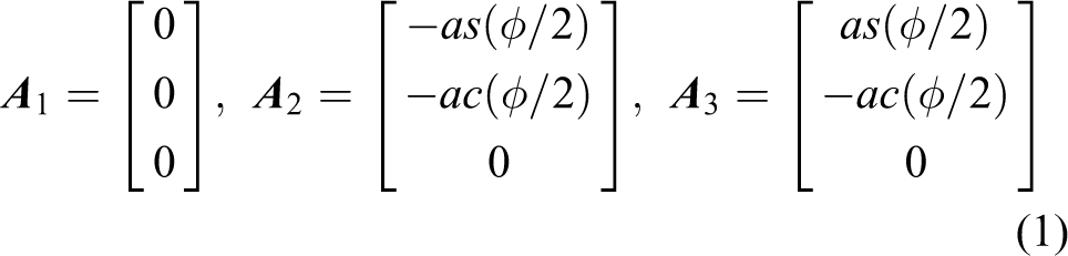
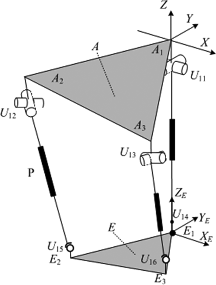
2-UPS+UP PM schematic diagram.
where
The center point of the upper universal joint in the coordinate frame {A 1} can be written as

where x1 is the design size of the leg mechanism and
Each point of the lower platform in the coordinate frame {E 1} can be described as
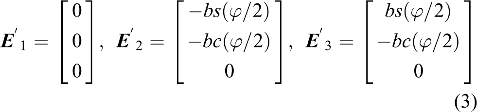
The lower end point of the UP branch and the center point of the lower universal joint in the UPS branch can be expressed as

where x2 and x3 are the design sizes of the leg mechanism and
Each point in the coordinate frame {E 1} could be transformed to the coordinate frame {A 1} as

where

Because of the UP branch constraint, the PLM has the geometric constraints relationship as

where
According to the established coordinate frame, we obtain

where l1i is the length change of each branch.
Substituting equations (4), (5), and (7) into equation (6) gives
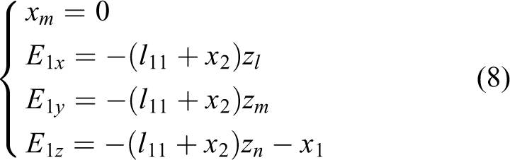
According to equation (8), Y–X–Z Euler angles are selected, and we obtain the final transformation matrix as

where α and β represent the rotation angles along the Y- and X-axes in the global coordinate frame.
Combining equation (8) with equation (9) leads to the following expressions

The length change of each branch could be expressed as

According to equation, expressions for the length change of UPS branch could be derived as

If point E 2 is selected to be the reference point, the length change analysis process of each branch is described below.
Point E 2 relative to the coordinate frame {A 1} can be described as

where
From equation (13), we have

Let

Solving equation (15) gives

Similarly, simplifying the first component of equation (13) gives

Solving equation (17) gives

According to the range of the angles α and β, we have that
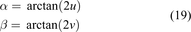
Combining equations (11), (12), and (19), the length change of each branch can be obtained.
If point E 3 is selected as the reference point, then the analysis process is similar to point E 2.
Velocity analysis and acceleration for the leg mechanism
According to equation (11), the length change of each branch in the PLM can be rewritten as
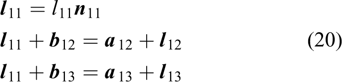
where l1i is the direction vector of each branch,
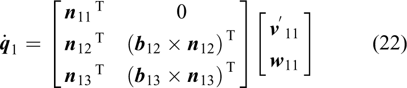
Taking derivative on both sides of each equation in (20), we have the velocity of each branch

where n1i is the direction vector of each branch,
Taking the dot product
where
Meanwhile, the velocity of the reference point

where
Taking the cross product

Combining equations (22) and (24) gives

where

using the same procedure, equation (23) is transformed as

where

and
If the inverse matrix of

where
Taking a derivative on both sides of equation (27), the transitive relation between the input and output for acceleration of the leg mechanism can be expressed as

where

Kinematics analysis of the walking robot
Inverse position analysis of the walking robot
Inverse position analysis of the walking robot implies knowing the position
According to Figure 5, the position of closed-loop equation in each leg mechanism can be described as
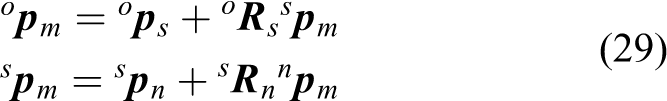
where
The position vector for the reference point mi of the lower platform in the leg mechanism relative to the leg mechanism coordinate frame {n} is described as

where
Combining equations (29) and (30) gives

In equation (31),
Combining inverse position analysis of the PLM and equation (31), the length change of each branch can be computed.
Velocity and acceleration analysis of the walking robot
Taking one derivative on both sides of each equation (29) and (30), we have

where
Simplifying equation (32), the reference point velocity of the lower platform in the PLM can be obtained as

where
Combining equations (27) and (33), the velocity of each branch could be obtained as

where g is the serial number of the PLM and g = 1, 2, 3, 4.
Taking derivative on both sides of equation (33), acceleration

where
Combining equations (33)–(35), acceleration

The foot trajectory and trotting gait planning
Motion planning of the robot is divided into two parts: the foot trajectory and the body motion.
The foot trajectory
The swing leg and the standing leg are the two motion states of the leg mechanism. The whole robot load is supported by the standing leg. The standing leg does not have relative motion between the foot and the ground. Thus the foot trajectory analysis is taken into account only for the swing leg.
A composite cycloid trajectory is proposed in the study by Sakakibara et al. 29 The cycloid trajectory is improved in the studies by Li et al. 28 and Wang et al., 30 and two sections curve planning are applied for the swinging of the leg mechanism in the movement cycle. It results in drastic change of the synthetic acceleration and does not have the uniform speed motion process. Thus, three sections curve planning are used for the swinging of the PLM in this article.
Considering the first PLM motion in YA1Z plane, no matter which axis the PLM swings relative to, the process of acceleration and deceleration is similar to the sine function and the expression is as follows

where Am is the amplitude and Tm is the movement cycle of the swing leg.
Integrating the above formula, the following equation is derived

where C1 is a constant.
According to the foot trajectory requirement, the curve should meet

When n = 2, the trajectory is an oblique line in the YA1Z plane. Although it is not conducive for the leg mechanism when crossing an obstacle, the trajectory referring to the Y-direction is suitable. As a result, the equation of displacement along Z is

When the n value is too large, it will result frequently in acceleration and deceleration moments along the Z-direction, which may not only cause the increasing of energy consumption but also induce the body mechanism tilting. In conclusion, n = 4 is selected for the Z-direction. The trajectory is divided into three sections along the Z-direction.
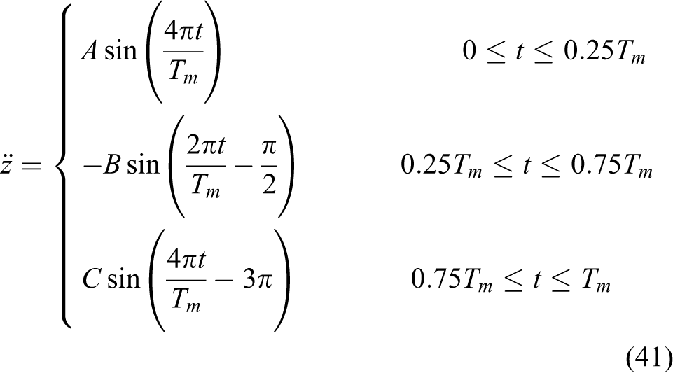
where A, B, and C are the amplitudes of the three sinusoids.
Integrating equation (41) twice, the following displacement curve is obtained

According to the requirement of the foot trajectory, the curve should meet

Substituting equation (43) into equation (42), the displacement cycloid equation can be obtained along the Z-direction as

Trotting gait planning
To the trotting gait, the human-carrying walking robot in this article is different from a general quadruped robot. The foot of the general quadruped robot is sphere, and when the foot is in contact with the ground, the point is formed. Thus, when performing the trotting gait, a straight line is made by leg mechanisms as the supporting area. Under this condition, stability of the robot is poor. Our proposed human-carrying quadruped walking robot with PLM performs differently since the surface contact is formed when its feet are in contact with the ground. Thus, the supporting polygon area still exists. There are two gait forms: 13-24 and 24-13 gait. The following analysis uses the 13-24 trotting gait as an example. Figure 7 shows the planning diagram of the 13-24 trotting gait. Center of Gravity (COG) indicates the gravity center position of the human-carrying walking robot. The closed polygon formed by red lines is the support polygon area of the walking robot. The motion process of the human-carrying walking chair is as follows:
Step 1: Leg 1 and leg 3 make a step first, respectively, as shown in Figure 7(a).
Step 2: When step 1 finishes, the body mechanism is adjusted, as shown in Figure 7(b).
Step 3: Leg 2 and leg 4 make a step, respectively, after the adjustment of the body mechanism ends, as shown in Figure 7(c).

Trotting gait 13-24 with individual adjustment the center of gravity. (a) Swing leg 1 and leg 3. (b) Adjusting the body mechanism. (c) Swing leg 2 and leg 4.
This cyclical gait only needs three steps.
Trotting gait simulation
In order to verify the theory analysis correctness of trotting gait planning and the foot trajectory, the trotting gait simulation is conducted. Assuming the initial state of the walking chair robot is when the UP branch is perpendicular to the ground, the initial height is H0 = 665.4 mm, the highest amplitude of the foot trajectory is H = 100 mm, the step size is S0 = 102.7 mm, and the period of motion is Tm = 5 s. The body mechanism motion function is

The swing leg mechanism is conducted using equations (40) and (44). Based on these motion functions and the mechanism parameters, the simulation is realized, as shown in Figure 8.

Trotting gait simulation. (a) The length change of all branches. (b) Velocity curves of all branches. (c) Acceleration curves of all branches.
Based on the simulation results, we can draw the following conclusions:
Leg mechanism 1 and leg mechanism 4 show a symmetric changing rule; leg mechanism 2 and leg mechanism 3 also show the symmetric changing rule. The simulation results highlight the symmetry and consistency, which shows that the kinematics model of the human-carrying walking chair robot is valid.
In the periods of 0–5 s, 10–15 s, and 20–25 s, the change for each branch of the leg mechanism is caused by the motion of the body mechanism. In the periods of 5–10 s and 15–20 s, the change of each branch is caused by the foot trajectory. Therefore, we find that the velocity change of each branch is discontinuous (in Figure 8(b)), but the motion of the walking robot is continuous.
The acceleration changes of the leg mechanism are smooth and there is no impact with ground in case of the origin position and terminal position, which shows that the foot trajectory planning is suitable.
According to the design of the PLM, it can be seen that the length range of the UP branch is in the interval of 591.4–891.4 mm and the velocity range is between 0 and 80 mm/s; the length range of the UPS branch is between 574 and 874 mm and the velocity range is between 0 and 80 mm/s. From Figure 8(a) and(b), it can be seen that their values are in the motion range.
Experiment research of the walking robot
Control system
For the robot, the controller and the driver are developed by our own research group, which are shown in Figure 9. One controller and one driver are used for each motor. The main control chip of the controller is PIC18F452 single chip computer, and the CPLD chip of the driver is XC9536-7VQ44C. This controller can realize three control modes (position control, velocity control, and current control), and the three control modes can be switched at any time.

(a) The controller and (b) the driver of motor.
If the position control mode is used, then the motor runs at its maximum velocity but its work velocity cannot be guaranteed; if the velocity control mode is adopted, then the motor runs at the specified velocity but its target position cannot be ensured. Based on these two control modes, the compound position control method is proposed. The method is that, firstly, the motor is controlled using the velocity mode between two discrete position nodes, meanwhile the position of the motor is detected and the accumulation error of the position is computed in this control period. And the desired velocity in the next control period is modified by applying the error. Finally, the target position and the work velocity can be guaranteed. The schematic diagram of the whole process is shown in Figure 10.

Compound position control method.
According to Figure 10, the accumulation error of the position in this control period is

where pd is the theoretical position and pr is the measured position.
The work velocity for the next control period is

where P is a proportional constant.
The velocity Proportional-Integral (PI) control law is

where kp and ki are proportional constant and integration constant, respectively, and vr is the measured velocity.
Experiment research of PLM 1
To verify the feasibility of the controller and the compound position control method, in this section, experiment research of PLM 1 is conducted based on the laser tracker Leica AT901. The process of the whole experiment is shown below: In the optimal workspace of the leg mechanism,
31
the reference point E
1 of the lower platform is planned as
Based on equation (48) and inverse kinematics of the PLM, the position and the velocity of the three branches are computed using a simulation software, as shown in Figure 11. The position and velocity relative to 0 of three branches are obtained by offsetting the simulation data, and then the results are saved as a binary file to be loaded into the control program. The control system and the measure system of the PLM are established as shown in Figure 12. The control system consists of three controllers, three drivers, Can bus, the power modular, and the host computer. The measure system includes the refection ball and the laser tracker. Positions of four screw holes connected with the UP branch on the upper platform are measured using the Leica T-Probe handheld measuring sensor and then four records are saved. Based on these four records, the coordinate frame {A
1} is established; meanwhile the initial position of the lower platform reference point E
1 is measured, as shown in Figure 13. The magnetic device is mounted at the reference point E
1 on the lower platform of leg mechanism. The reflection ball is fixed on the magnetic device and it reflects the laser. The leg mechanism works in accordance with the planning trajectory and then the experimental data are saved in an excel file.


Inverse kinematics analysis of the leg mechanism. (a) The length change of three branches. (b) Velocity of three branches.

Trajectory tracking experiment of the leg mechanism. (a) Rear view. (b) Front view.

Establishing the coordinate system and measuring the initial position.
Finally, the theoretical curve and the experiment curve are shown in Figure 14, where we can draw the following conclusions:
The experiment trajectory is closely related to the theoretical trajectory. However, there are some errors at the initial position and the end position due to the mechanism error. Comparing the radius of theoretical trajectory with the radius of experiment trajectory, the maximum error is 2.454 mm.
The experiment trajectory of the leg mechanism is stable and the fluctuation is little noticeable. Thus, the designed controller is suitable for the experiment requirement.
The position error of the whole motion process is not accumulated using the compound control method. Thus, the compound position control method is feasible.

Contrast of theoretical value and experimental value.
Experiment research for the trotting gait of the walking robot
Based on the above theoretical analysis and experiment test of PLM 1, in this section, the trotting gait of the human-carrying walking robot is conducted. The serial number of leg mechanism and the motion direction are shown in Figure 15. And the motion process of the trotting gait is as shown in Figure 16. In these figures, the motions of Figure 16(a) and (e) are used to adjust the height of the body mechanism. The motions of Figure 16(b)–(d) are applied at the implement step.

Number of the leg mechanism and motion direction of the robot.

Motion of the dynamic walking gait 13-24. (a and c) Adjusting body mechanism. (b) Swing leg 1 and leg 3 mechanism. (d) Swing leg 2 and leg 4 mechanism. (e) Backing to the initial height.
During the process of the whole experiment, the motion of the human-carrying walking robot is in line with the theoretical gait planning and the gait has a smooth motion. Thus, the correctness and rationality of the trotting gait planning is verified.
Walking experiment research of the human-carrying walking robot
For the walk experiment, it is necessary to determine the payload capacity of the robot. The payload capacity is relative to many factors, such as the structural parameters, the structural arrangements, the thrust of linear actuator, the inertial force, the inertial moment, and so on. They could be expressed as the following equations

where

where
When the structure and the motion trajectory of the robot are decided, the

where [τ] = 98 MPa and A ≈ 7.07 mm2. We can obtain F ≤ 692.86 N.
According to the structural design of the robot, the thrust

Comparing equations (52) and (53), we find that the structural strength of the universal joint is enough. So the thrust of the linear actuator can be described as

where fgi
is the thrust of each branch and
Meanwhile, fgi also can be described by the following equation

where Ct is a constant.
From equation (55), we observe that the current reflects the thrust of the linear actuator. We can obtain the payload weight by measuring the current of the each branch and the thrust is maximum when the current is maximum.
So we could add payload on the walking robot continuously and observe the current data of each branch. Figure 17 is the current change curve of each branch when the payload is 57 kg.
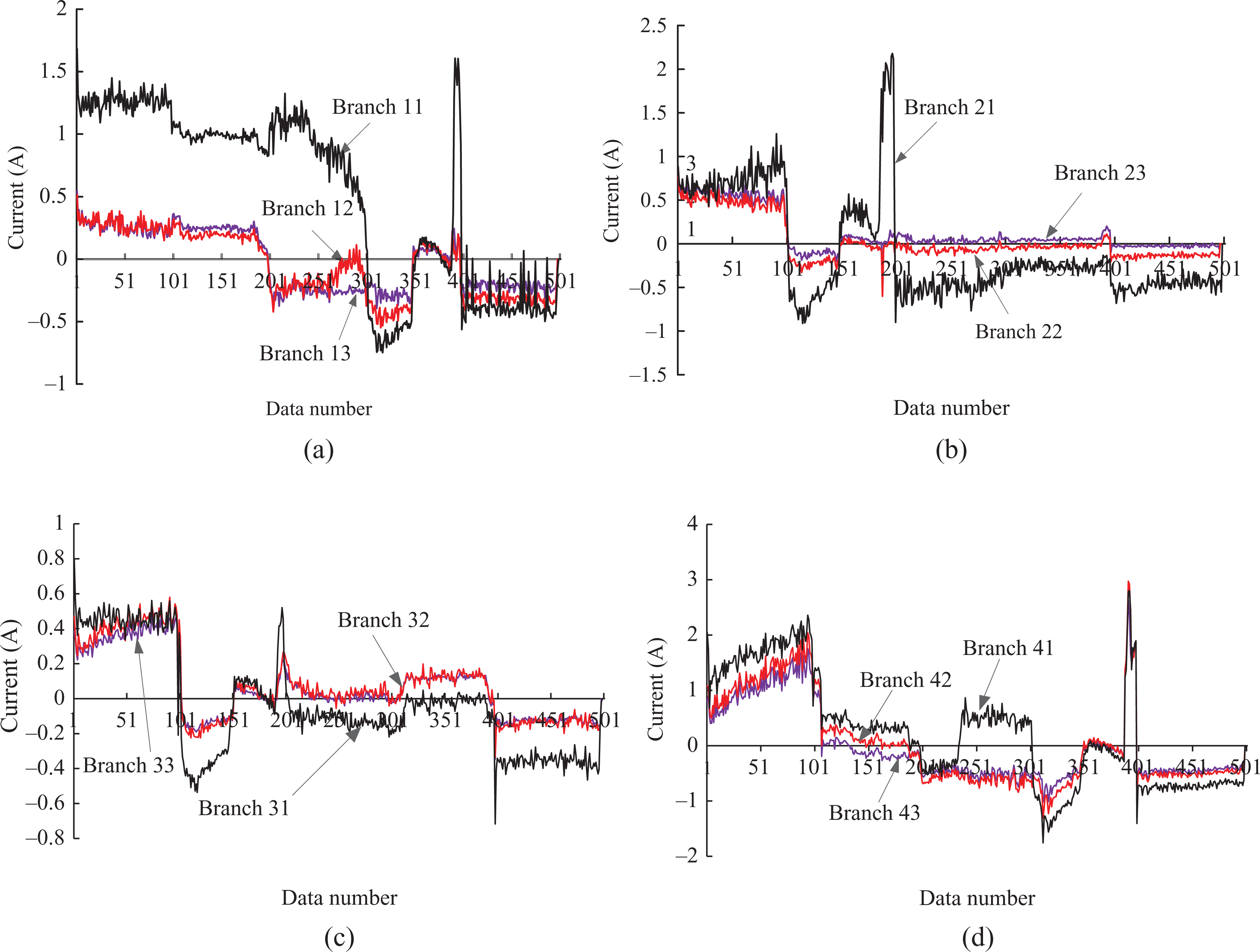
Current change curve for each leg mechanism of the human-carrying walking chair robot. Current change for each branch of (a) leg 1, (b) leg 2, (c) leg 3, and (d) leg 4.
From these four figures, we can draw the following conclusions:
The current change of the branches 2 and 3 of each leg mechanism is the same. The result is consistent with the motion law.
The current change for branch 1 of each PLM is the maximum, such as branch 11 with 1.7 A, branch 21 with 2.4 A, branch 31 with 0.6 A, and branch 41 with 3 A. We obtain that the rated current of the linear actuator is 3 A. So the maximum payload of the human-carrying walking robot is 57 kg.
Figure 18 shows the human-carrying experiment when the payload is 47.5 kg.

Human-carrying experiment of walking robot.
From the motion of human-carrying walking robot, we can obtain that the gait planning and the designed controller are reasonable, and the payload capacity is enough.
The walking chair robot is placed on an electronic platform scale, and the measured result is 49.2 kg, as shown in Figure 19. We find that the payload–weight ratio of the walking chair robot is 1.16. It is higher than i-foot robot, Hobo FX-1, and WL-16RIV. Thus, we conclude that the walking robot has great payload capacity.

Weight measurement of the walking chair robot.
Conclusions
Based on the 2-UPS+UP PM, the human-carrying quadruped walking chair robot with PLM has been proposed and the prototype has been designed and manufactured.
Combining the human-carrying walking chair robot, the kinematics for the leg mechanism and the body mechanism are derived. Through the experiment on simulating the foot trajectory and the trotting gait, we have verified that the kinematics model is valid.
The control system of the human-carrying quadruped walking robot has been designed, and the compound position control strategy has been studied. Through experiment verification, it is found that the controller and the driver are suitable to experiment requirements for the control system of walking chair robot and the compound position control strategy is feasible.
The trotting gait experiment of the human-carrying walking chair robot has been conducted and the results show that the motion of the human-carrying walking chair robot is in line with the theoretical gait planning and the gait has a smooth motion. The correctness and rationality of the theory of planning gait has been verified.
Based on the current change of the linear actuator, we have concluded that the payload capacity of the human-carrying walking robot is 57 kg.
The present work will be extended in the future from the following two aspects:
Mechanism optimization: At present, the payload capacity of the walking chair robot is only 57 kg and is lower than the weight of an average person. So the whole walking chair robot will be optimized to increase the payload capacity of the walking chair robot in the future.
Human in the loop control strategy research: Because of changing with the height, weight, and motion of the passenger on the seat, the security and stability of the human-carrying walking chair robot are affected. We need to consider these changes when the control strategy is researched. In the future, we plan that the passenger is regarded as the loop of the control system and research on the passenger influence to the whole control system.
Footnotes
Declaration of conflicting interests
The author(s) declared no potential conflicts of interest with respect to the research, authorship, and/or publication of this article.
Funding
The author(s) disclosed receipt of the following financial support for the research, authorship, and/or publication of this article: This work is supported by National Natural Science Foundation of China (no. 61075099), Specialized Research Fund for the Doctoral Program of Higher Education (no. 20131333110006), FP7-PEOPLE-2012-IRSES: Marie Cuire Action “International Research Staff Exchange Scheme (no. 318902), and High-level Personnel Funded Project in Hebei Province.