
Abstract
During extraterrestrial planet exploration programs, the existing exploratory mode has some limitations, such as the exploratory range of the rover is limited. In this article, a concept of a novel legged robot is introduced which has inbuilt the features of lander and rover, including landing and walking capabilities as well as being deployable, orientation adjusted, and terrain adaptable. Furthermore, the rover can also be launched and work together with the robot to extend the exploratory range, and the legged mobile lander plays the role of base camp. The concept and features of the proposed robot are outlined in three stages. Firstly, the motion characteristics of the novel legged robot mapping its functions are extracted, which can be divided into global and local motion characteristics. Secondly, the structures of legs are designed according to the extracted motion characteristics, mainly composed of upper and lower parts. Thirdly, numerous structures of legged mobile landers are obtained and presented by assembling the same or different structures of legs. The number of overconstraints is selected as the qualitative index to evaluate the mechanisms. Finally, the five functions of the novel robot mentioned above are verified through taking a typical example by simulation in a software.
Introduction
Some astronomical bodies, such as Moon or Mars, are of explorative scientific significance to many nations. The lander and the rover play important roles for extraterrestrial planet exploration. 1 At present, there have been different types of landers and rovers, which are launched together in the abovementioned exploratory missions. The lander should fold away before the descent, and then unfold during descent. To protect the robot from shocks during landing, it needs a buffer function to absorb the energy generated during the contact with surface. After 1anding, the lander will perform in site exploration while the rover will move around the landing site to undergo major investigation.
Certainly, over the last decades, many nations have invested in development and risk-reduction activities for a new generation of planetary landers provided with carrying instruments and several technological add-ons to the lunar surface and other airless bodies.
As for lunar landers, Surveyor 1 2 was the first lunar soft-lander in the unmanned Surveyor program of the National Aeronautics and Space Administration (NASA, United States). Luna 16 3 was the first robotic probe to land on the Moon and return a sample of lunar soil to Earth. As for Apollo Program, the structural subsystem, design requirements, configuration description, design and manufacturing problems, and design verification of the lunar module were discussed in the study by Weiss. 4 There are some other significant lunar landers, such as EuroMoon 2000 5 designed by the European space agency, ELENE-B 6 designed by Japan, Altair lunar lander 7 , Chang’e 3 8 –11 , and Peng et al. Furthermore, 9 depicts the deployable and lockable soft-landing mechanism. In addition, some Mars landers, such as Viking 1 lander 12 and Phoenix lander, 13 were proposed. Most of the given landers with four legs have the common components. Landing legs consist of a main bumper mechanism, an auxiliary bumper mechanism, a middle platform, and a footpad. The lander needs to possess some important capabilities such as unfolding legs before landing and landing buffer to absorb shock produced during the contact with surface.
As for rovers, many wheeled rovers were proposed and studied, such as Sojourner rover, 14 Spirit and Opportunity rovers of the Mars Rover mission, 15 Jade Rabbit rover, 16 Shrimp and SOLERO rovers, 17,18 and ExoMars-E rover. 19 Most of the existing rovers with wheels have the limited capability to traverse tough terrains and have problems with the orientation adjustment of the body. Particularly, some conceptual robots with a wheel-legged mobile system are designed to expand their maneuvering range, enhancing their exploration capability, such as ATHLETE 20,21 and Spider-bot. 22 However, the functions of lander and rover are still separated, which means that the lander is immovable while the rover cannot be used for landing. Furthermore, the rover needs to possess some important capabilities such as walking (or mobility), orientation adjustment, and terrain adaptability, which enable the robot to walk on some extreme terrains to explore.
Being immovable after landing, the most important task of the lander is to help the rover to step on the surface. Then, the rover accomplishes the exploration work. This mode for exploratory mission has some limitations. 23 –25 (1) Because the lander is immovable, it leads to limit the exploration range of the rover, because it has to receive energy or other aids from the lander after extravehicular activity. The rover and astronauts cannot go to a faraway place from the landing site. That is to say, even though both of the two robot can keep working forever without damage and lacking of energy, it is also impossible for the robots to explore the areas beyond the security range. (2) In the future, since the exploratory range of extraterrestrial planet will be extended, the terrain becomes more and more complex, which includes not only the even terrain, but also some other various terrains, such as slop which is full of obstacles, gully, and some obstacles. It is a great challenge for the wheeled rover to go across these terrains. Therefore, as the requirement of the exploratory mission gets more complex, novel legged mobile landers can be a solution to the above issues or limitations.
In this article, we focus on designing the innovative mobile landers, combining the characteristics and capabilities of lander and rover. It is noted that in this explorative mode, the rover can also be launched to explore together with the legged mobile lander. The mobile lander mainly plays a role of lander during launching and landing. After landing, the robot has two working modes. As for mode 1, the legged mobile lander mainly plays a role of base camp. It stays in the original landing site, and the rover explores the environment in the limited range. After the rover accomplishing the exploration in the limited range, the lander moves to other site to support the rover to explore other area. The most range of the surface can be explored by repeating these process. As for mode 2, the legged mobile lander also could be seen as a rover to perform exploratory tasks, such as investigating geology of lunar surface, determining mineralogy and composition of minerals, studying internal structure of the astronomical body, and exploring the space environment. Consequently, the advantages or merits are detailed as follows 11 : (1) it expands the maneuvering range and enhances the capability of exploration; (2) it has more capability than conventional lander and rover; ultimately, the cost of mission, such as manufacturing and launching, can be reduced greatly; and (3) in comparison with a wheeled rover, the mobile lander walks across obstacles more efficiently and effectively.
Therefore, a novel practical mobile lander is necessary and meaningful in exploratory missions. The key issue of designing a lander is related to designing the structures of legs, which depends on the corresponding type synthesis method. Many researchers have paid attention to the type synthesis of some mechanisms and proposed several types of mechanisms by means of graph theory, 26 Lie group and differential manifolds, 27 –29 GF set, 30,31 screw theory, 32 –35 and position and orientation characteristic approach. 36 However, there is less literature available to discuss the conceptual structural design of mobile landers with multifunctions (the function of lander and rover) systematically.
The aim of this article is to investigate the novel design of a legged mobile lander to let the lander walk inspired by the configurations of existing landers and the experience of walking robot from our laboratory. 37,38 This article is detailed in seven sections. “Overall design concept for the legged mobile lander” section outlines the overall concept and design procedure for a legged mobile lander. The global and local motion characteristics of the legged mobile lander and its legs are presented, which are derived from its functions or capabilities in “Motion characteristics analysis of the legged mobile lander” section. In “Leg design of the legged mobile lander” section, the structures of legs are designed and presented. “Some typical legged mobile landers” section brings some types of legged mobile landers assembled by the same or different structures of legs. Furthermore, the actuated joints are selected and some mechanisms are selected as the solutions by taking the number of overconstraints as the qualitative index. The multifunctions of the proposed landers are verified by simulation in a software (such as ADAMS 2014) in “Verification of multifunctions for mobile lander by simulation” section. Finally, “Conclusion” section contains the conclusions.
Overall design concept for the legged mobile lander
The schematic of the legged mobile lander is presented in the middle of Figure 1, which consists of the body and four legs. The structure of each leg can be divided into two parts, the upper part and the lower part. The upper part is a parallel mechanism and the lower part has the terrain adaptability mechanism connected with a footpad. Furthermore, the upper part has three limbs, the main backbone and the two slightly thinner auxiliary backbones. The energy absorber, such as a metal honeycomb, can be installed into the limbs of the upper part of the legs and the linkage between the middle platform and the footpad. During landing, the main backbone will absorb the vertical impact shock and the auxiliary backbone will absorb the horizontal impact shock.

Concept of constructing a legged mobile lander.
The former three functions (deployable function, landing buffer function, and walking function) can be seen as the main functions and the latter ones (orientation adjustment and terrain adaptability) can be regarded as auxiliary functions. Particularly, for the landing buffer function, the active joints of the mobile lander are locked and the robot can be regarded as an immovable structure.
For facilitating the conceptual idea, the design concept is explained in three stages, as shown in Figure 1. Furthermore, the corresponding methods of each stage are shown in Figure 2. In the beginning stage, stage 1, integrated motion characteristics 30 mapping multifunctions of the mobile lander are extracted. Considering the complexity of these functions, the corresponding motion characteristics are divided into two categories to design the legs, the global motion characteristics attached to the body to describe its motions and the local motion characteristics distributed on the leg describing those of the respective leg. Next, in stage 2, the structure of the legs for the mobile lander is designed to satisfy the motion characteristics mapping all the mentioned functions. In stage 3, legged mobile landers are achieved by assembling the same or different legs designed in the first phase. Then, actuated joints are selected in different ways for the mobile lander. Finally, a typical mechanism is selected as a study object to verify that the legged mobile lander can realize the five functions by simulation.

Design procedure of the legged mobile lander.
In what follows, each stage will be explained in detail and several illustrative examples will be provided.
Motion characteristics analysis of the legged mobile lander
Extraction rules and representation of motion characteristics
To extract the motion characteristics
30
mapping functions of the mobile lander, extraction rules are proposed. Rule 1: For rotation motion characteristic (R-characteristic), if the end-effector
can rotate around a certain axis, there exists an R-characteristic whose axis
coincides with the aforementioned axis. Rule 2: For translation motion characteristic (T-characteristic), if the
end-effector can translate along a certain direction, there exists a
T-characteristic with a direction aligned in the same above certain direction.
Note: more motion characteristics are obtained by following the above two rules.
Symbols definition and explanation.

R-characteristic: rotation motion characteristic; T-characteristic: translation motion characteristic; 2-D: two dimensional; 3-D: three dimensional.
Motion characteristics analysis of the mobile lander
According to the extraction rules presented above, it is easy to get the corresponding
motion characteristics after analyzing the multifunctions (shown in Figures 1 and 2), which will be explained, respectively, as
follows: 1) Deployable function
To adapt the fairing envelope of the launch vehicle, all the legs shall be folded and locked before descent. Consequently, the legs need to rotate around a certain axis attached to the body. So, according to the extraction rules, there exists an R-characteristic whose axis coincides with the specific axis, as shown in Figure 3(a).

Motion characteristics mapping functions. (a) Deployable function; (b) landing buffer function; (c) walking function; (d) orientation adjustment; (e) terrain adaptability; and (f) integration.
2) Landing buffer function
To avoid the robot from damaging due to shocks during landing, it needs to be equipped with energy absorbers in order to use the landing buffer function. Thus, the corresponding motion characteristic is achieved. Each leg of the mobile lander can translate along the direction of its axis. That is to say, there is a T-characteristic, as shown in Figure 3(b). To use the landing buffer function, a metal honeycomb (one kind of energy absorber) is installed along the direction of the T-characteristic to absorb the shocks. If there is an R joint between the middle platform and the base platform, the directions of two linkages connected by it are collinear to each other to reach the dead point. 39
3) Walking function
For this function, the end of each leg needs to perform a 3-D trajectory. The end of each leg needs to translate along any direction in space, because the end of leg is considered as a point, not a rigid body. Thus, there are 3-D T-characteristics, as shown in Figure 3(c). Furthermore, the 3-D T-characteristics are realized by other distributions of motion characteristics shown in Figure 4(a) to (f).

Motion characteristics mapping walking function. (a) RRT; (b) RTR; (c) TRT; (d) RRR; (e) TRR; and (f) RTR.
4) Orientation adjustment
For this function, the body is regarded as a moving platform, which can translate in any direction in space and rotate around any axis on the horizontal plane. Consequently, there are 3-D T-characteristics and 3-D characteristics attached to the body, as shown in Figure 3(d).
5) Terrain adaptability
For this function, the global terrain adaptability requires the legs to possess one T-characteristic along the axial direction. The local terrain adaptability requires the end of the leg to rotate around any axes. That is to say, there are 3-D R-characteristics attached to the end of each leg, as shown in Figure 3(e).
As a result, it is easy to obtain the integration of motion characteristics by getting the union of all the motion characteristics, as shown in Figure 3(f).
For facilitating the design of the mobile lander, the integration of motion characteristics is divided into two kinds: global and local motion characteristics, as shown in Figure 5(a) and (b). The motion characteristics of the body are regarded as global, determined by all legs while those of each leg are called local motion characteristics.

Motion characteristics of the legged mobile lander. (a) Global motion characteristics; (b) local motion characteristics; (c) lower part of leg; and (d) upper part of leg.
Determination of the motion characteristics of the legs
The global motion characteristics are six dimensional (6-D), which include 3-D T-characteristics and 3-D R-characteristics. Thus, it only requires each leg to have 6-D motion characteristics. Furthermore, Figure 5(b) depicts the local motion characteristics of the leg, which satisfies this requirement given by the global motion characteristics.
The leg of the mobile lander consists of two parts, an upper part and a lower part. The lower part owns the 3-D R-characteristics designed by a spherical joint, as shown in Figure 5(c). The upper part is regarded as a parallel mechanism whose moving platform allows for the rest of the motion characteristics except the 3-D R-characteristics, as shown in Figure 5(d). Among these motion characteristics, the 3-D T-characteristics are realized by other distributions of motion characteristics shown in Figure 4(a) to (f). In addition, because of the existence of other two motion characteristics (one T-characteristic and one R-characteristic), three kinds of motion characteristics for the upper part of the leg are easily obtained and are represented as (RR) O T, RTR, and CT (C stands for cylindrical motion characteristics combining an R-characteristic and a T-characteristic with the same direction, and () O , meaning that the axes of the R-characteristics intersect at point O), which are presented in Figure 4(a) to (c), respectively.
According to the scope of this article, the mobile lander on the basis of the first kind of union of motion characteristic ((RR) O T) is designed and implemented. Furthermore, other cases can be designed by the same method.
Leg design of the legged mobile lander
The structures of the legs are obtained by combining the structures of the upper and lower parts. The lower part allows for the 3-D R-characteristics, designed by a spherical joint. The upper part of the leg is regarded as a parallel mechanism with motion characteristic (RR) O T, which is made up of an end-effector and a fixed base (body of the legged mobile lander), linked together by three limbs. The structural design of the legs of the mobile lander will be detailed in this section.
Determination of motion characteristics for limbs of legs
Based on the motion characteristic movement theorem 30 and intersection rules 31 of type synthesis theory, the motion characteristic (RR) O T of the moving platform for a three-limb mechanism is the intersection of the motion characteristics produced by all limbs, which can be expressed as

where {LMC i } represents the motion characteristic of the ith limb. {RMC} denotes the motion characteristic of the moving platform. ∩ is a set intersection operator. For example, A ∩ B represents mechanisms A and B connected with each other in a parallel form.
It is concluded from equation (1) that (1) each leg must contain a 2-D rotational characteristics and one translation characteristic; (2) the motion characteristic of each limb must satisfy the following equation

where
Based on the intersection rules 31 of motion characteristics, there exist six cases of arrangements of motion characteristics of limbs according to the target motion characteristic of the end-effector, that is, (RR) O T, which will be described as follows and shown in Figure 6(a) to (f), respectively.
Case I:

Arrangement distributions of LMC.(a) Case I; (b) case II; (c) case III; (d) case IV; (e) case V; and (f) case VI. LMC: motion characteristics for limbs of legs.
Figure 6(a) depicts one case
arrangement of motion characteristics of limbs (LMCs). It consists of three limbs with
different motion characteristics. The first limb’s motion characteristic is (RR)
O
T, the second one is
(RR) O T refers to the axes of two R-characteristics, intersecting at a point O;
It is noted that, in this case, the axis of L1R1 (which means the
first R-characteristic of the first limb) coincides with that of
L2R1. The axis of L1R2 is parallel to that
of L2R2. The direction of the T-characteristic of the first limb is
parallel to the plane of the 2-D T-characteristics of the second limb and the third limb
is located at any position between base and moving platform. Case II:
Figure 6(b) shows one case
arrangement of LMCs. It consists of three limbs with three kinds of motion
characteristics. The first kind of motion characteristic is (RR)
O
T, the second one is
It is noted that the planes spanned by the two R-characteristics of the first and second
limbs are parallel to each other in this case. Case III:
Figure 6(c) shows one case
arrangement of LMCs which consists of three limbs with three kinds of motion
characteristics (RR)
O
T,
It is noted that the axis of L1R1 coincides with that of
L2R1. The axis of L1R2 is parallel to that
of L2R2. The direction of T-characteristic of the first limb is
parallel to the plane of the 2-D T-characteristics of limb 2 and the third limb is located
at any position between base and moving platform. Case IV:
Figure 6(d) shows one case
arrangement of LMCs, which consists of three limbs with two kinds of motion
characteristics. The first kind of motion characteristic is (RR)
O
T and the second one is Case V:
Figure 6(e) shows one case
arrangement of LMCs, which consists of three limbs with only one kind of motion
characteristics. It is noted that the arrangement condition is special. The axis of
L1R1 coincides with that of L2R1. The axis
of L3R1 is parallel to that of L1R1. The axes
of L3R2, L3R2, and L3R2
are parallel to each other and the plane spanned by the 2-D T-characteristics of each limb
be parallel to each other at the same time. Case VI:
Figure 6(f) shows one case arrangement of LMCs which consists of three limbs with different kinds of motion characteristics. The geometrical conditions of arrangement of three limbs are the same as that of case V.
Limb design for legs of the mobile lander
There are five kinds of motion characteristics of limbs to design the legs of the mobile
lander, that is, (RR)
O
T,
1) (RR) O T
According to the procedure of determining structures of limbs of the GF set theory, two types of limbs are synthesized: (RR) O P and UP. Furthermore, the schematic diagram of UP limb is depicted in Figure 7. Some simple joints, such as the revolute (R), prismatic (P) joints, and some combined joints such as cylinder (C), spherical (S), universal (U) joints, pure-translation universal joint (U*), and the parallelogram joint (Pa), are used in this article.

Kinematic limb with motion characteristic (RR) O T.
2)
This motion characteristics includes one R-characteristics (without movable property),
one movable R-characteristic, and 2-D T-characteristics, where the 2-D T-characteristics
are perpendicular to the axis of movable R-characteristic. According to the procedure of
determining structures of limbs, the limbs with motion characteristic
Configurations of limbs with


Two typical configurations of a limb with
3)
There are five motion characteristics of limb with this motion characteristic
Configurations of limbs with


Two typical configurations of a limb with
4)
There are five motion characteristics of limb in this type. According to the procedure of
determining structures of limbs, the limbs with motion characteristic
Some typical configurations of limbs with


Two typical configurations of a limb with
5)
There are six motion characteristics of limb in this case. According to the procedure of
determining structures of limbs, the limbs with motion characteristic
Some typical configurations of limbs with


Two typical configurations of a limb with
Structure design for leg of the mobile lander
The structure of the legs is synthesized by assembling three corresponding limbs (listed in Tables 2 to 5) under the six cases of arrangement conditions (as shown in Figure 6). These typical cases of configurations of legs are listed in Table 6 corresponding to their distributions.
Typical configurations of legs with (RR) O T motion characteristic.

To scale the function of terrain adaptability to a larger extent, experience of existing landers and walking robot of our laboratory 37,38 is used. For this purpose, spherical passive joints of three degrees of freedom (DOF) are used. The typical legs are sketched by combining the upper part and the lower part, as shown in Figure 12.

Some typical legs with (RR) O T motion characteristic. (a) Case I: UP&UPR&UPS; (b) case I: UP&URR&URS; (c) case II: UP&UPU&UPS; (d) case II: UP&URU&URS; (e) case III: UP&SPR&UPS; (f) case III: UP&SRR&URS; (g) case IV: 2-UPS&UP; (h) case IV: 2-URS&UP; (i) case V: 3-UPR; and (j) case V: 3-UR7R.
Figure 12(a) and (b) synthesizes
case I as shown in Figure 6,
composed of three kinds of limbs with
Figure 12(c) and (d) synthesizes
case II as shown in Figure 6,
composed of three kinds of limbs with
Figures 12(e) and 14(f) depict case III as shown in
Figure 6, composed of three
kinds of limbs with
Figures 12(g) and 14(h) have the details about case IV
as shown in Figure 6, composed of
three kinds of limbs with
In particular, Figure 12(i) and
(j) brings case V, as shown in Figure 6, composed of only one kind of limbs with
Some typical legged mobile landers
Determination of the legged mobile lander
A mobile lander is constructed by connecting the body with four legs, listed in Table 6. The structures of mobile landers are classified into two kinds in terms of types of legs: one with the same structure of legs, and the other one with different structures of legs.
A large amount of mobile landers with all structurally symmetric legs are obtained by assembling a body with the same structures of legs chosen from Table 6. Consequently, some configurations of the legged mobile landers with symmetrical structures are depicted in Figure 13.
Typical schematic diagram of mobile landers with symmetrical structures. (a) Case I: UP&UPR&UPS; (b) case I: UP&URR&URS; (c) case II: UP&UPU&UPS; (d) case II: UP&URU&URS; (e) case III: UP&SPR&UPS; (f) case III: UP&SRR&URS; (g) case IV: 2-UPS&UP; (h) case IV: 2-UP&URS; (i) case V: 3-UPR; and (j) case V: 3-URR.
Numerous mobile landers with different structures of legs are synthesized by assembling a body with different legs chosen from Table 6. Consequently, two schematic diagrams of the legged mobile landers with asymmetrical structures are shown in Figure 14.

Typical schematic diagram of mobile landers with asymmetrical structures.
Selection of the actuated joints of legs and overconstraint analysis
Usually, the actuated joints cannot be selected arbitrarily. The selection of actuated joints must ensure that, in a general configuration, the DOFs of the mechanism with all of the actuated joints blocked are zero.
According to the principle stated above, the rule to select actuated joints for these
mobile landers (shown in Figures
13 and 14) is described
as follows. The P or R joints between the middle platform and body are suggested to act as
actuated joints. The symbols of actuated joints are represented with an underscore, such
as
In the above section, numerous types of mechanisms are obtained. It is necessary for the further structure design to present the criteria of type evaluation. As we know, the evaluation indexes include qualitative and quantitative evaluation indexes. Since this article mainly focuses on the novel structure design of legged mobile lander without considering the detailed parameters, it only focuses on the qualitative index. The number of overconstraints 33,34 is usually taken as an index, which denotes the geometrical constraints and complexity of mechanisms. An overconstrainted mechanism may cause large internal force and increase the cost of manufacturing and difficulty of assembling. During working phase, the linkages of mechanisms tend to be deformed under some heavy loads. Consequently, owing to the existing of overconstraints, some linkages cannot satisfy the initial assembling conditions, which lead to that the mechanism cannot perform the desired motion or even cannot work. Conversely, the mechanisms without overconstraints have some metrics, such as it has efficient performance; it can be assembled easily. Therefore, the more overconstraints the mechanisms has, the more difficulties the structural design has. In order to decrease the possibilities of the legged mobile lander failure, it is necessary to select the less or none overconstaint mechanism.
The number of overconstraints of the mechanism can be achieved, as follows

where Δ is called the number of overconstraints if Δ > 0. c denotes the order of the wrench system of parallel mechanism’s platform, m means the total number of limbs, and ci presents the order of the wrench system of leg i.
Consequently, the number of overconstraints of these six cases can be obtained, respectively, which are case I: Δ1 = 5 − 3 = 2; case II: Δ2 = 4 − 3 = 1; case III: Δ3 = 4 − 3 = 1; case IV: Δ4 = 3 − 3 = 0; case V: Δ5 = 6 − 3 = 3; case VI: Δ6 = 5 − 3 = 2. It is easy to receive the conclusion: the number of overconstraints of case IV is the smallest among these six cases, which equals to zero. That is to say that the mechanism of case IV’s performance may prior to others. Therefore, in the following section, this case will be taken as an example to verify the functions by simulation.
Verification of multifunctions for mobile lander by simulation
One type (2-UPS&UP) of the presented mobile landers (as shown in Figure 15) is taken as an example, to verify that the
integrated robot possesses the five functions by simulation: deployable function, landing
buffer function, walking function, orientation adjustment, and terrain adaptability. Note
that other configurations of robots can be verified by the same method. The typical legged
mobile lander is made up of four same structural legs and the body. Each leg has the same
structure, which consists of one main backbone, two same auxiliary backbones, and a footpad.
Since this article mainly focuses on the novel design of the mechanisms without considering
the size synthesis, a group of suitable parameters will be selected for the legged mobile
lander to simulating without optimized design, which are shown in Figure 15. It is noted that the unit of length is
millimeter. Parameters of one typical legged mobile lander. 1) Deployable function
The deployable function implies that the legs of mobile lander rotate around a certain axis
attached to the body. The configurations of two statuses of the mobile lander (including
stowed and deployed positions) are depicted in Figure 16. The angle can be changed from 64° to 85°
without interference of linkages. Two statuses of the mobile lander. (a) In deployed position and (b) in stowed
position. 2) Landing buffer function
To fulfill this function, in order to absorb the shock, the energy absorber such as a metal honeycomb is installed into the limbs of the upper part of legs and the linkage between the middle platform and the footpad. 20 Accidently, the structure of legged mobile lander is similar to that of the existing Chang’e 3 lander accidently. That is to say, after detailed strength design, it will increase the possibility for the joints to satisfy the mechanical requirements for landing.
It is noticed that if there are R joints between the middle platform and the body, the
directions of two linkages connected by R joint are collinear to each other to reach the
dead point
39
to keep the robot from shock damage during landing. For example, the directions of
linkages L1 and L2 should be collinear to each other, as shown in
Figure 17(a). Furthermore, if
there are P joints between the middle platform and the body, in order to protect the joints
more effectively, a lockable soft-landing mechanism is necessary to be assembled into the
linkage as shown in Figure 17(b). Peng
9
dipicted more detailed information of lockable mechanism. Particular configuration of leg with (a) dead point and (b) lockable soft-landing
mechanism. 3) Walking function
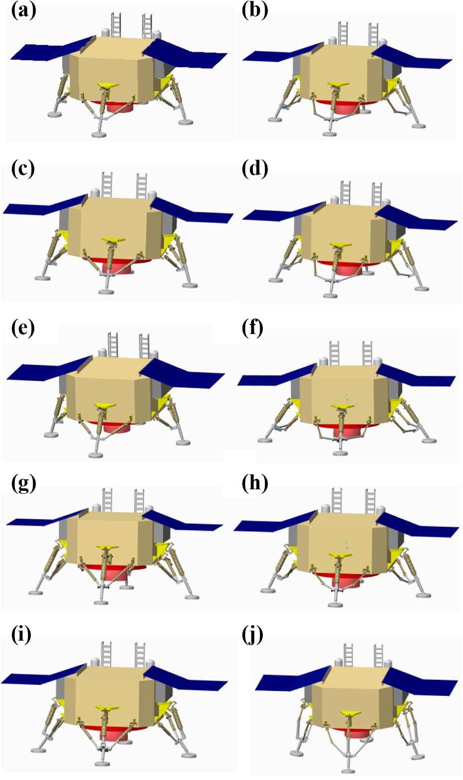
One static gait (which is shown in Figure 18) together with the robot physical attributes (such as mass and inertia) is simulated by software (such as ADAMS) to realize whether it accomplishes its function of walking. Figure 19 shows that the prototype robot walks forward, which implies that the robot has the walking function.
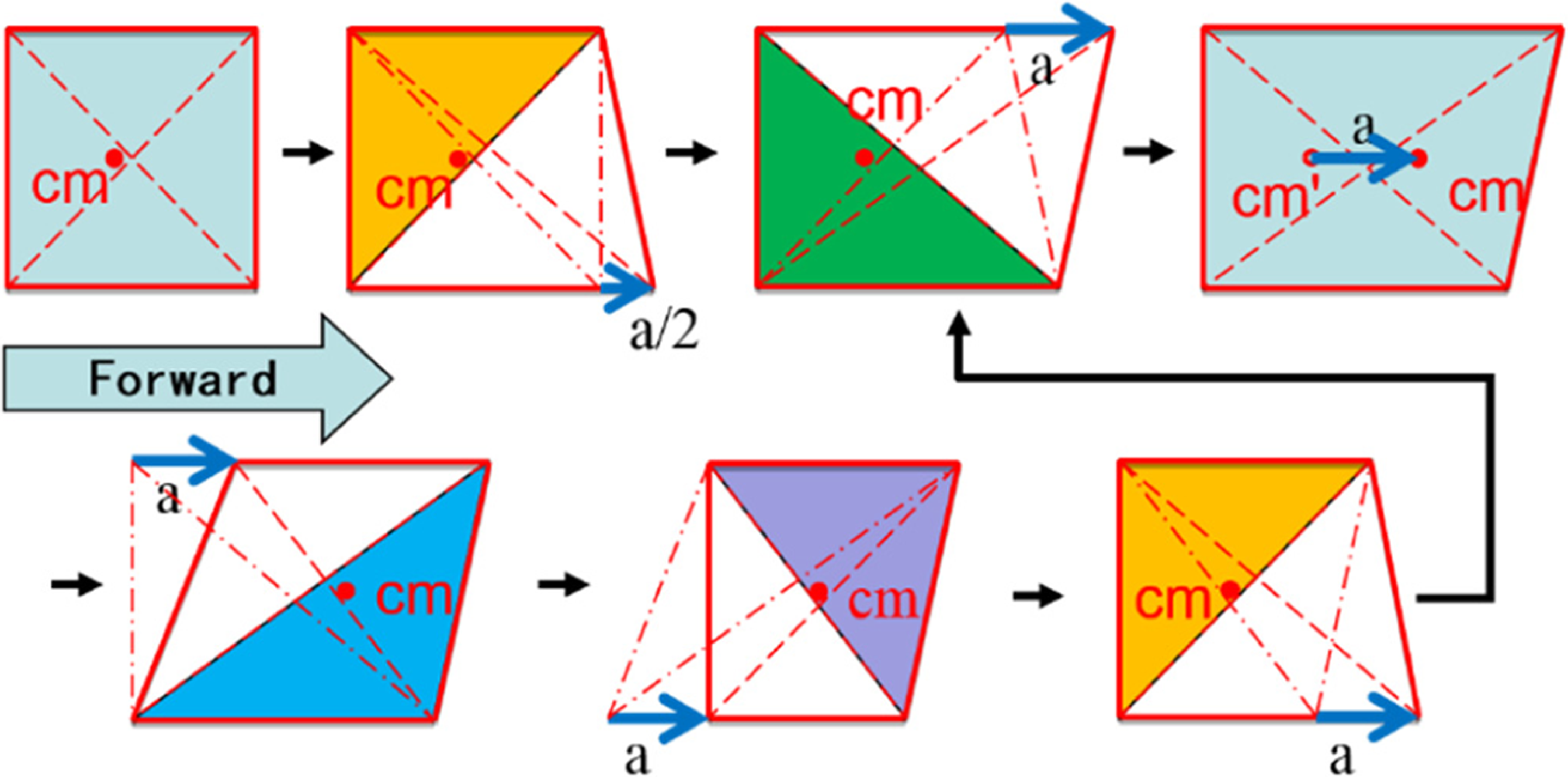
One gait of the mobile lander.

Robot walking simulation.
4) Orientation adjustment
In the software, the active joints are actuated by proper functions to accomplish the function of orientation adjustment. Figure 20 shows different configurations of body of the mobile lander, which implies that the robot possesses the function of orientation adjustment. Furthermore, both the pith and roll angle can reach up to 15°.

Orientation adjustment of the mobile lander.
5) Terrain adaptability
The mobile lander has global and local terrain adaptability. As for the global terrain adaptability, the legs extend and retract. For local terrain adaptability, the footpad of the leg rotates around any axes via the passive S joint. Figure 21 shows the robot standing on uneven terrain by simulation, which demonstrates that it possesses the function of terrain adaptability.

Terrain adaptability of the mobile lander.
Conclusion
The novel concept of the legged mobile lander combining the features and capabilities of lander and rover is introduced in this article, because the existing exploratory mode has some limitations, such as the exploratory range of the rover is limited. The legged mobile lander has some advantages detailed as follows: (1) it expands the maneuvering range and enhances the capability of exploration; (2) it has more capability than conventional robots; ultimately, the cost of mission, such as manufacturing and launching can be reduced greatly; and (3) in comparison with wheeled rovers, the mobile lander walks across obstacles more efficiently and effectively.
The systematic procedure containing three stages and the corresponding method for the novel design of the legged mobile lander are proposed. Following the procedure, numerous legged mobile landers with the same or different legs are achieved and presented. Some architectures of the proposed legs of the robot have the potential for other practical industrial applications, such as light machining tools for deburring, polishing, and grinding of curved surfaces. The design method mainly has three steps, which includes obtaining the motion characteristics of robot, which are extracted from the task, determining the motion characteristics and their arrangements of limbs, and designing the structures of the limbs. This method starts from the requirements of task, which has strong applicability and advantages. Firstly, the motion characteristics of robot can be obtained by the extraction rules rapidly. Secondly, the motion characteristics with the detailed directions and positions are presented by some symbols intuitively and vividly. Thirdly, it is easy to get the motion characteristics and arrangement of the limbs. Fourthly, the structures of limbs can be achieved rapidly according to the motion characteristics. Moreover, the key method proposed in this article provides reference for the structure design of walking robots.
Footnotes
Acknowledgments
The authors would like to thank the National Natural Science Foundation of China and the Research Fund of State Key Lab of MSV, China. They would also like to thank Mr. Kamran Ali Shah from the School of Naval Architecture, Ocean and Civil Engineering, Shanghai Jiao Tong University for his support in writing this article.
Declaration of conflicting interests
The author(s) declared no potential conflicts of interest with respect to the research, authorship, and/or publication of this article.
Funding
The author(s) disclosed receipt of the following financial support for the research, authorship, and/or publication of this article: This work was supported under the projects from the National Natural Science Foundation of China (grant nos 51735009 and 51323005) and the Research Fund of State Key Lab of MSV, China (grant no. MSV-ZD-2016-08).