
Abstract
In this article, a new wall-climbing robot platform with protection devices for city inspection is developed. After an overall structural introduction, the main protection devices of the robot are described in detail, including the support frame, the Ethylene Vinyl Acetate (EVA) shell, and the airbag. The support frame plays the roles of chassis and protection framework, so integrative and lightweight design is required. The EVA shell covers the support frame, and it protects the robot from overturn falling down from the wall. The airbag is designed both for sealing and protection. The mechanical model of the airbag is established based on the engineering thermodynamics theory and is used for force analysis when robot falls down on the ground. In addition, two-level distributed control system is designed to achieve the control of fan speed, straight moving, differential steering, position servo, and video transmission. To verify the feasibility of the climbing robot, many experiments are conducted, that is, experiments of movement, load capacity, adaptability to the wall surfaces, endurance, camera, sensor, and antithrow. The results show that the actual working performance of the climbing robot is favorable, thus providing a train of thought and inspiration for the antithrow design of climbing robot.
Keywords
Introduction
Recently, the number of high-rise building has increased along with the development of technology to cope with the increase in population. 1 Manual work at elevated heights suffers from shortcomings such as high laboring intensity, low efficiency, and high risk. 2,3 Therefore, climbing robots have been a very attractive research topic. There are a great number of potential applications to increase operational efficiency and protect human health and safety from hazardous tasks such as cleaning the facades of high-rise buildings, 4 –6 exploring natural and artificial environments, 7,8 inspection, 9 and so on. At present, many studies about techniques and applications of climbing robots at scientific research institutions have made significant achievements. 10
Unlike other robotic systems, the gravitational effect is so dominant that different approaches are required for the robot system to operate on the façade. 1 To overcome the gravitational effects, several studies have been conducted using various methods such as magnetic adsorption, 3,9,10,11 –16 biomimetic adsorption, 17,18 gripping type, 19 rail-guided type, 20 negative pressure adsorption, 21,22 and so on. Grieco et al. developed a six-legged climbing robot prototype able to climb on ferromagnetic walls carrying high payloads available for inspection, maintenance, and intervention tasks in industrial environments. 12 Kalra and Gu designed a tracked wall-climbing robot using magnetic adsorption to inspect oil tank walls. 3 Tang et al. developed an omnidirectional wall-climbing microrobot with magnetic wheels. 13 Magnebike was a magnetic wheeled robot with high mobility for inspecting complex-shaped structures. 14 Omnidirectional magnetic wheeled climbing robots can be used to inspect ferromagnetic structures. 15 Wu et al. designed noncontact adjustable magnetic adhesion mechanism for a wall-climbing welding robot. 16 Daltorio et al. adopted insect-inspired attachment mechanisms for Mini-Whegs TM to climb steep surfaces. 17 He et al. focused on the development of a novel wet adhesion pad for wall-climbing robots that can scale walls, and the experimental results show that the climbing ability of the robot with the pads is exceptional. 18 Longo and Muscato developed the Alicia3 climbing robot composed of three-module robot for automatic wall inspection using negative pressure adsorption. 21 Hillenbrand et al. developed a climbing robot called CROMSCI with negative pressure adhesion for inspections. 22
Magnetic adhesion mechanism does not require time to generate a sufficient adhesive force and enables fast locomotion, but it is suitable for attaching to only ferromagnetic surfaces, therefore leads to limited applicability. Similar to magnetic adhesion mechanisms, climbing robot that use biomimetic adhesion does not need energy to stay on the surface or pressure differences to climb, but it has a few disadvantages, such as a very low payload and sensitivity to surface conditions involving dust. Gripping mechanisms for adhesion have been suggested to enable climbing robots to travel along 3-D complex environments, but it has a large weight and a limited locomotive speed for driving heavy systems. The robot employing rail-guided adhesion consists of the climbing mechanism, the mechanism of movement, and a supporting mechanism, which led to large size and high cost. Negative pressure adsorption, which is the most commonly used adhesion method, can be widely adopted for less rough surfaces because it enables strong attachment to the surfaces regardless of materials such as glass, ceramics tiles, and cement. Therefore, it is more suitable for the modern city walls using the negative pressure adsorption compared with the other ways. Although the technology of this method is well developed, there are still two problems: first, this kind of technology is costly; second, there are huge potential security problems during the robot sliding down or overturning along the wall surfaces in high places. Therefore, it is vitally important to equip protection device for the robot. The present protection devices of the robot are as follows.
The climbing robot protected by rotary wing is developed by Miyazaki University, 23 as illustrated in Figure 1(a). Safety rope has been applied to improve the safety performance of the both robots. The curtain-wall inspection robot is developed by Beihang University, 24 as illustrated in Figure 1(b). A support post installed in the tail of the robot generates a torque contrary to the overturning torque, so as to strengthen the overturning resistance and guarantee the safety of the robot, as shown in Figure 2. Fraunhofer Institute IFF in German proposed a climbing robot protected by a huge balloon to clean the glasses inside of the roof. The volume of the balloon is 200 m3. The huge balloon is considered to cooperate with cable winch to control shifter and adjust attitude of the cleaner. Meanwhile, the balloon can prevent the robot from falling. It could be also landed artificially to maintain the robot.
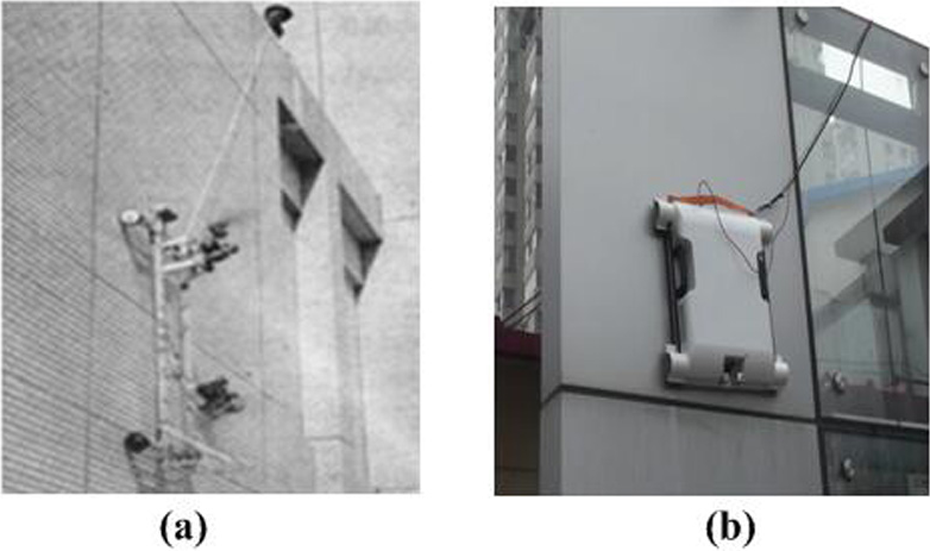
Climbing robot protected by safety rope: (a) the robot with rotary wing and (b) the inspection robot.

Climbing robot protected by support post.
Each of these approaches has advantages and drawbacks that it is necessary to be balanced with the needs of the climbing robot. The safety rope is the protection device which is the most widely used. However, there are still some defects in security. Despite the protection of the safety rope, the robot would suspend in the air or crash into the wall, which causes some damage to the robot or the wall. In addition, the robot would crash into the ground because the rope doesn’t work in time when the robot lands in the lower place. Therefore, a comprehensive protection device deserves to be researched. In this article, a new climbing robot with protection device will be introduced, and the robot has the characteristics of low cost, simple structure, and easy assembly.
The remainder of this article is organized as follows. “Overall structure” section presents the overall structure of the climbing robot. “Design of support frame” section describes the design of the support frame in detail. “Protection device and mechanical model of airbag” section focuses on the protection device, including Ethylene Vinyl Acetate (EVA) shell and airbag with good waterproof/dustproof performance, and analyzes the mechanical model of airbag. The control system of the robot is given in “Control system” section. Finally, the performance parameters are tested through the experiments and the differential pressure transducer is tested in this platform in “Experiments and application” section.
Overall structure
The climbing robot mainly consists of moving mechanism, absorption device, sealing device, support structure, and protection device included in this article. The basic function of the robot includes working on general walls, realizing the real-time return of videos collected by microcamera, and ensuring the safety of the robot. The negative pressure absorption is adopted because of good adaptability. The wheeled locomotion is used as moving mechanism because of easy control, simple steering, and good adaptability.
The absorption device consists of a Brushless Direct Current Motor and a centrifugal impeller, as shown in Figure 3(c). The impeller is driven by the highly rotating motor to expel the air in the sealing chamber, so as to generate the certain negative pressure in the chamber. The four wheels mounted on the robot are all driving wheels to ensure enough actuating force to overcome its own gravity. The two wheels on each side are connected with synchronous belt transmission and are driven by a DC servo motor, resulting in differential steering, as shown in Figure 3(a). The sealing device of the robot is a piece of airbag, which has a certain kind of flexibility, so that it can be tightened on the support frame and form the negative pressure cavity together with the supporting plate, as shown in Figure 3(c). Stiffness of the airbag can be regulated by changing the aeration quantity. The protection device is composed of the airbag and the EVA shell: the airbag is supposed to absorb the impact force from the bottom and surroundings of the robot, and the EVA shell is supposed to absorb the impact force from the top of the robot, which will be introduced in “Protection device and mechanical model of airbag” section in detail. Fan frame, supporting plate of moving mechanism, airbag support, and negative pressure plate are designed as a whole, named support frame, will be introduced in “Design of support frame” section in detail. Besides, there is a microcamera in the front of the robot, which is able to lift up and down according to the demand, as shown in Figure 3(b). There are also safety ropes and a flexible handler mounted on the robot.

Overall structure: (a) walking mechanism, (b) external structure, and (c) internal structure.
Design of support frame
Support frame is the most important part of the robot, because the other parts are all mounted on it. Moreover, it is supposed to provide support to EVA shell and airbag and to protect vulnerable parts from impact force. Given that the performance improvement of the climbing robot, it is necessary to reduce the weight on the premise that guarantee the stiffness.
Shape design
There are some drop ways of the robot, and overturning of which can cause the most serious damage to the robot. That is to say, colliding with the ground at the top of the robot will cause a huge impact force to the robot’s shell, and the vibration associated with which may damage the inner parts as well. Therefore, the design thought of the protection device is that the top of the robot shell adopts buffer material, and then the structure of support frame should minimize vibration impact force as far as possible.
The robot has been simplified to simulate the states in ADAMS when falling happens. The function of sealing ring is ignored, and the support of robot main body and the four wheels are given. When the robot is falling down, the states are as follows:
The robot stays still by exerting a force that’s perpendicular to the wall. The robot falls down under gravity effect when the force is removed after 0.1 s. Gravity is equivalent to a constant force of an application point on the adsorption active line. CONTACT is exerted between the wheels and the wall, and also between robot main body and the wall. The wheels are connected with the robot main body by Revolute. The parameters of the robot are designed as the realities of situation. The distance between the center of the wheels and the wall is 25 mm; the distance between the front and rear wheels on the same side is 351 mm; the distance between the right and left wheels on the different side is 476 mm. The distance between the robot and the simulation ground is 2 m; the simulation time is 1 s; the simulation steps are 100. The center of the robot is needed to gradually move away from the wall. The distances between the center of the front wheels and the wall, and the rear wheels and the wall, are measured, respectively. The distance between the center of gravity and the wall is about 11–46 mm. The eight sets of data are as shown in Figure 4.
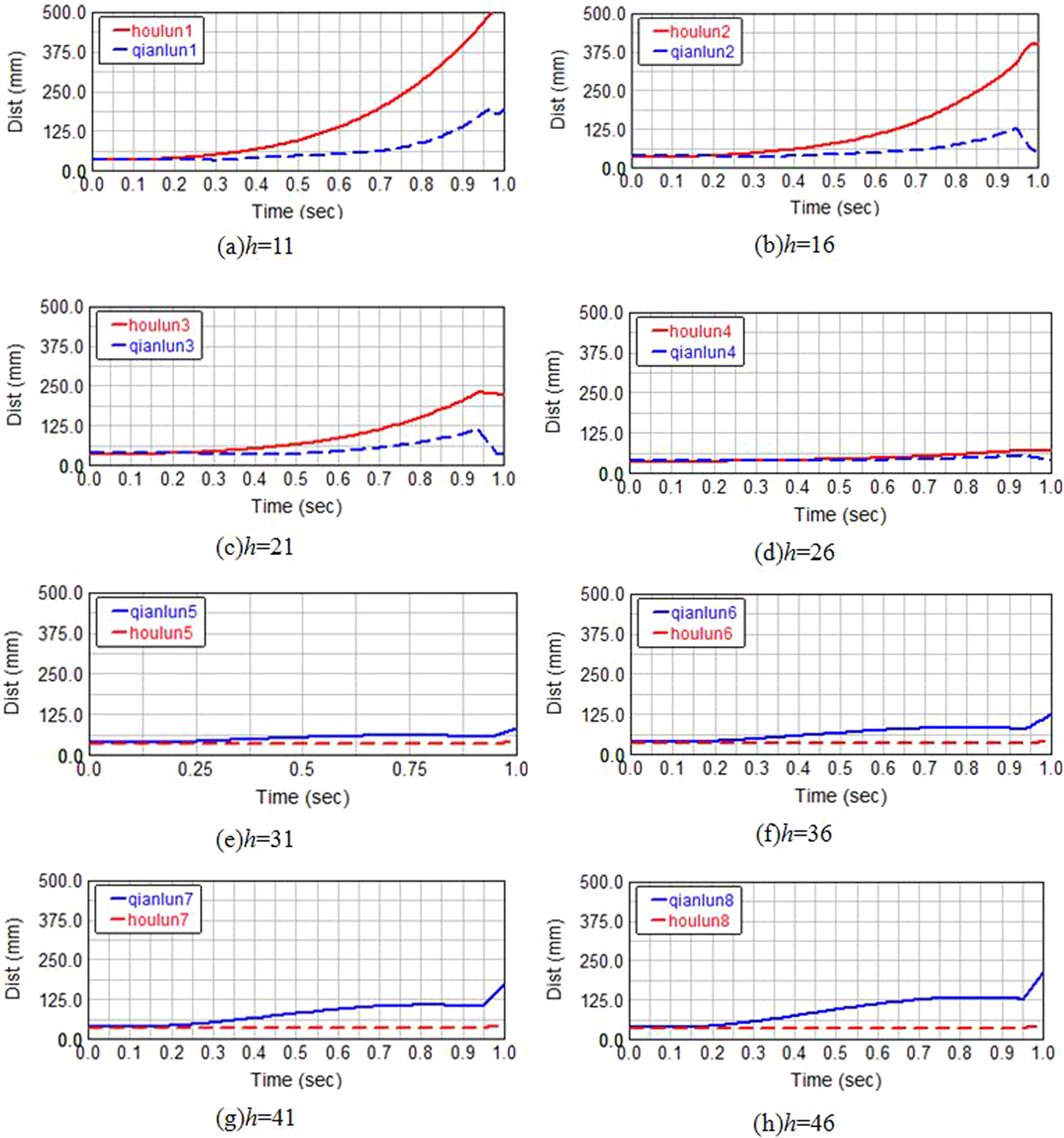
The distance variation between front and rear wheels and wall in the case of different values of h.
When the center of gravity is excessively low, the robot will fall forward, which led to the event of impact between the rigid wheels and the ground. When the center of gravity is excessively high, the robot will overturn backward during the sliding down along the wall, and it ultimately causes the event of impact and larger impact force between the tail and top of the robot and the wall. When the center of gravity is available, the robot will slip along the wall first and then overturn backward. The impact is rather small between the top of the robot and the ground. It is needed to minimize the impact forces in all directions of the robot to ensure the robot’s safety performance, thus benefitting to the design of the protection device. According to the above conclusion, the center of gravity should choose the right height of about 26 mm. Of course, the height of the center of gravity limits from 26 to 30 mm to ensure the robot can overturn backward. The turtle shell has good compressive and shock resistance. The load is transmitted from the center point to surroundings, and the stress distribution is basically uniform without stress concentration phenomenon in this process. The fore and the aft end of the shell are bobbing up and down relative to its original position that transforms overall kinetic energy into local strain energy and dissipates the energy through local vibration during the collision. The shell with ribs could increase the lumen area, guarantee structural strength, and reduce the quality under pressure loaded on a small area of the top. Therefore, the turtle shell is adopted as the support frame.
The drop attitude of the robot is illustrated in Figure 5(a). The robot would swing back and forth around the center of the shell with arch surface, thus converting the overall kinetic energy into the local strain energy, and then expend the energy through local vibration when the backend of the robot touched down and leaned back. The final shape of the frame is illustrated in Figure 5(b) and (c).
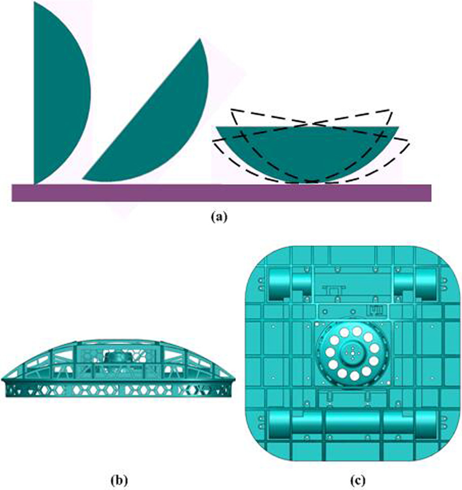
Support frame: (a) drop attitude, (b) side view, and (c) top view.
Layout and lightweight design
Analysis of overturning resistance
Climbing robot has a high requirement for the overturning resistance. Therefore, it is necessary to analyze the force situation for reliable design of the robot. Assuming that the robot moves up with constant smoothly, and the force diagram of the robot is demonstrated in Figure 6.

Force diagram.
Where, v is the constant speed;
According to the force diagram, the overturning conditions can be obtained as

where,
The conditions of anti-overturning are analyzed, so that some conclusions can be drawn: the distance between the front wheels and the rear wheels should be reduced as far as possible on the premise of satisfying movement conditions; the weight of the robot should be minimized and the center of gravity should be lowered; if
Layout of support frame
The moving mechanism is embedded in the support frame at 10 mm to lower the body’s center of gravity and reduce the overturning force needed to overcome, as described in Figure 7. The position of various parts is designed on the negative pressure plate of the support plate in the shell frame. The camera and its driving actuator are placed on the front of the robot, which makes it convenient to capture the environment ahead of robot. Three lithium-ion batteries in series adopted as the power are mounted at the backend of the robot to increase the walking stability and to avoid the layer of “heavy top and light bottom.” The circuit board, wireless module, and negative pressure transducer are put on the both side of the central of the support frame to improve the safety performance of the robot by considering the empty space and less affected by the impact force from the both side of the central. The size of the frame is 330 × 330 × 85 mm3 and the chamber diameter is 160 mm.

Layout of support frame.
Lightweight design
Several reinforcing structures are adopted to realize the function of the support frame, as illustrated in Figure 8, such as: (1) arch brace, which is used to enhance stiffness and strength of a long beam and is allowed to absorb a certain amount of impact force; (2) triangle bracket, which can guarantee the intensity while saving weight and be suitable for arch structure with shorter chord; (3) force-passing support, which can pass a certain amount of the impact force to the side of the frame when the impact force is imposed upon the top of the robot and share the impact force due to the strong side structure and less parts assembly to reduce the impact force passed to easily-worn parts; (4) honeycomb and X-brace structure, which are suitable for large plane and have lighter weight and same stiffness compared with girder. Meanwhile, the shock absorption property of the structure is good for increasing the antithrow ability. In addition, there are airbag support and rib design on the frame.

Reinforcing structures.
The process of force transmission when the top of the robot is under impact force is demonstrated in Figure 9. The impact force will act on the four main middle columns after buffering and damping by EVA shell when the impact force exert on the top of the robot. And then, the impact force spreads to surroundings through force-passing. The reinforcing structures can improve the integral strength of the robot in this process.

Force transmission.
Protection device and mechanical model of airbag
It is necessary to protect the three sides of the robot: the roof, the bottom, and the backend, as demonstrated in Figure 10. The EVA shell, airbag, and safety rope are designed to implement protecting function. The EVA shell and the airbag will be described in detail in the next sections.
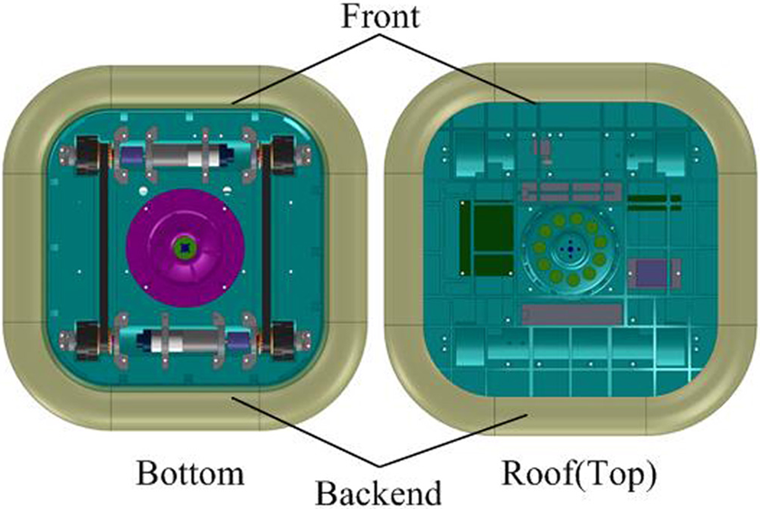
The sides of the robot.
EVA shell
The shell using Ethylene Vinyl Acetate (EVA) material plays a significant role in the performance of crash resistant, because it would bear the maximum impact force when the robot fell down. The robot would slide down along the wall and lean back causing great impact force on the top of the robot with the safety rope not working. EVA shell is supposed to absorb all the impact force applied on the top of the robot and a part of impact force applied on the surroundings of the robot. Therefore, the material of the EVA shell must have good ability of shock absorption. The shell is chosen as the best protection device due to its good pliability and short for environmental stress cracking resistance. The airbag will touch the ground and overturn the back, and the EVA shell will absorb vibration by swing itself when falling happens.
The inside shape of the shell fits perfectly with the shape of the support frame. A part of the airbag can be wrapped by the surroundings of the shell to share some impact force imposed on the airbag lest the airbag bursts due to great impact force when the robot is hitting with the ground. The thickness of the shell is 30 mm and the shape is concave outside and convex inside. The outside of the shell can be milled by numerical control machine but the inside cannot. To facilitate the processing of the shell, the inside shape is changed to the step shaped that there is a step every 3 mm, as shown in Figure 11. The shell is fixed on the frame by its four built-in positioning blocks because of the elasticity which can embed in the support frame, as illustrated in Figure 12.
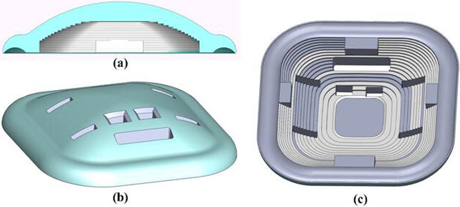
EVA shell: (a) section view, (b) the inside shape, and (c) the outside shape.

Positioning of the shell.
Airbag
The airbag is one of the most important parts of the robot. As mentioned above, it is not only the sealing ring of the negative pressure chamber but also the protection device of the bottom and the surroundings of the robot. Therefore, it is necessary to analysis the airbag. Thermoplastic polyurethanes (TPU) is adopted as the material of airbag. It has an excellent water proof property, high abrasion resistance, high tensile strength and elongation, and strong bounce back. Sliding friction exists between the airbag and the wall during the moving process of the robot. The stiffness of airbag can be adjusted according to its inflating volume. The properties of TPU transparent film are in favor of realizing the aforementioned functions of airbag. The stiffness of airbag has a significant impact on pressure distribution and safety protection. Therefore, it is necessary to establish the stiffness model of the airbag.
Properties affected by airbag
There are two main properties of the robot affected by the airbag:
Pressure distribution: The robot is absorbed on the wall relied on the negative pressure, recorded as The value of

Shock absorption: All the impact force on the bottom and the other impact force on the surroundings of the robot are absorbed by the airbag. The safety rope is mounted on the front of a robot. The rope tightens up immediately to stop suspended objects falling down when the speed of the objects exceeds 0.2 mm/s. If the robot is suspended in the air, the bottom of the robot may collide with the wall. At this time, the airbag can resist the impact force in a degree to protect the robot. The ability of shock absorption of the airbag is related to the stiffness. The impact force can be estimated, which is benefit to the research of antithrow of the robot.
It is necessary to establish the mechanical model of the airbag through the above analysis.
Mechanical model of airbag
According to the effect of the airbag, there are two directions stiffness to be calculated. Figure 13 describes the situation that the bottom of the robot contacts with the wall, in which the four sides of the airbag contact the wall under the negative pressure, so the stiffness of the airbag in this case is called surface stiffness in this article. In the similar way, Figure 13(b) describes the situation that the backend of the robot hits the ground and the force is only applied on one side of the airbag, so it is called side stiffness.

Stiffness: (a) surface stiffness and (b) side stiffness.
Surface stiffness
A section of the airbag is selected arbitrarily when the four sides of the airbag contact with the wall. The length of the unit is assumed to

Force diagram of airbag section.
Assuming that the restoring force of the airbag under the payload is

where

where
The gas equation of the state in this case is expressed as

where
Assuming that

The approximate equation
Substituting equation (6) into equation (4) and then omitting the second-order small quantities, the following equation can be obtained.

If

where
Therefore, the stiffness of the airbag K can be expressed as
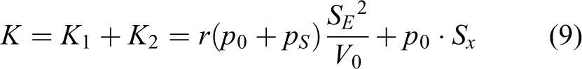
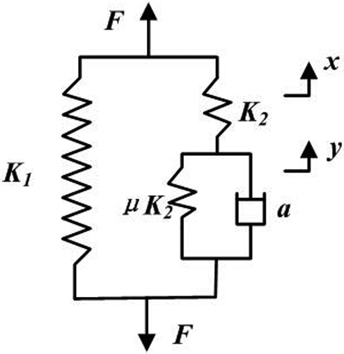
The mechanical model of the surface stiffness of the airbag can be equivalent to the model of two springs in parallel according to equation (9), as demonstrated in Figure 15.
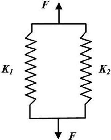
Equivalent model of surface stiffness.
Equations (3) to (9) refer to the analysis of the surface stiffness of airbag. The surface stiffness of airbag can be computed by solving equation (9). The pressure force distributed on the wheels can be solved by combining the surface stiffness of airbag with the negative pressure be measured to make quantitative processing to the pressure distribution and determine the distance between the airbag and the wheels. The pressure should be distributed to the wheels as much as possible at the same time of ensuring sealing performance. In addition, the rotational speed of the fan can be properly adjusted in case of ensuring driving force by means of experiment and numerical calculation to use the limited battery power rationally and increase endurance. The influence factors of the surface stiffness of airbag, which include volume, the effective stress area, and change rate of the effective stress area, can conduct design to the shape of the airbag.
Side stiffness
The airbag can be divided into two parts when the airbag hits with the ground at one side: one is the side of the airbag contacting with the ground and the other is the rest of the airbag, which is considered as constant volume for its small change during working.
Two parts of the airbag under the payload have gas exchange as demonstrated in Figure 16.
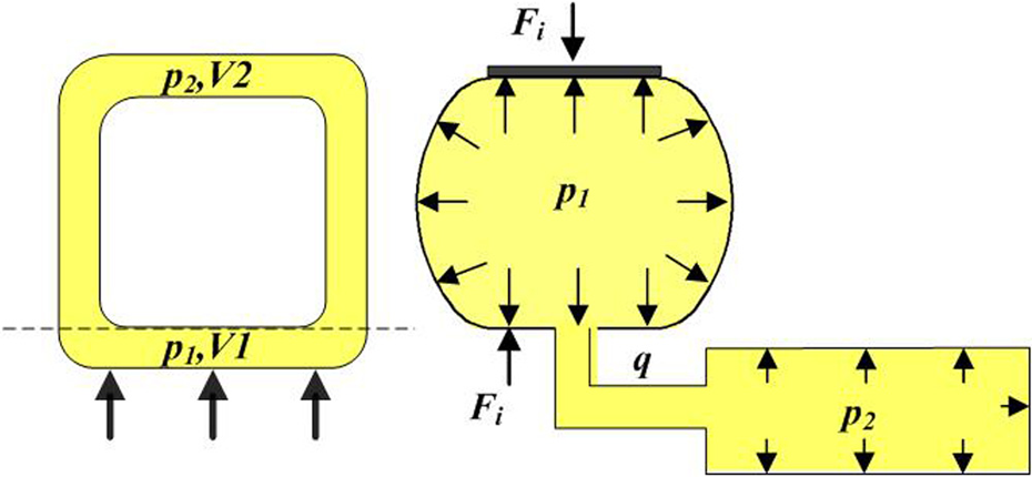
Force diagram of airbag.
The state equations of gas in this process can be explained by
where
Applying the method of series expansion and omitting the second order and the small quantities, the following equations can be deduced as
Using equation (11),

Substituting equation (12) into equation (4), the following equation can be obtained

If

where y is called the equivalent displacement that gas flows.

where
Assuming

Therefore, the mechanical model of the side stiffness of the airbag is obtained as

where

The equivalent model of the side stiffness of the airbag is demonstrated in Figure 17.
Equivalent model of side stiffness.
It can be seen from airbag’s edge stiffness model (equations (10) to (18)), airbag has buffered effect on impact. The effects depend on the specific parameters. Then, the ability to withstand impact of airbag is evaluated by means of experiment and calculation.
Control system
The required functions for the climbing robot are the control of fan speed, moving smoothly, differential steering, position servo, and video transmission. It is necessary to realize the stronger stability, high sensitivity, and good rapidity for the robot to guarantee to receive commands in real time and complete the actions quickly and accurately based on the commands. In addition, there are several restrictions in volume and in weight of the control system. Therefore, two-level distributed control applied in the control system of the robot. The whole control flow of the control system is shown in Figure 18. The personal computer interface of the robot is developed by adopting Eclipse 4.5.0 software. Wireless Fidelity (WIFI) module is adopted as the communication module. Transmission Control Protocol/Internet Protocol (TCP/IP) protocol is adopted as the communication protocol and Socket is applied to communication interface with lower computer. Serial Communication Interface (SCI) is applied to data transmission to realize the control of the upper computer to lower computer.

Process of control system.
Android system equipment containing human–computer interface, such as mobile phone, tablet PC, and so on, is connected to wireless WIFI module. The control information is sent to the lower computer through the interface and received by the WIFI module through the wireless Local Area Network (LAN). The WIFI module is connected to the main control board of the lower computer. The lower computer allows the data, which are transferred to the lower computer via a serial port, to be parsed based on communication protocol, that is, TCP/IP protocol. The corresponding actions of the climbing robot are completed according to the parse result. The motion data are fed back to the main control board by the encoder installed on the walking motor to implement feedback control. The measurement data from differential pressure sensor installed in the negative pressure cavity are fed back to the main control board to monitor the pressure changes. The monitoring circuits of the voltage and current are designed to monitor the current and voltage in the circuit in real time. The videos taken from camera are transmitted to the operating equipment through WIFI module to monitor the surroundings. In addition, the data are also transmitted back to the terminal device to master the working status of the robot.
The design requires of the interface are comprehensive, beautiful, and operability. The interface contains the following control function: motor control, WIFI state, camera setting, fan control, servo control, and Warning, as shown in Figure 19. The interface is more convenient and has higher visual quality, compared with the remote controller and laptop.

Interface.
Experiments and application
The prototype of the robot is illustrated in Figure 20 and the support frame is made by 3-D printing. Movement test, load capacity, adaptability to the wall surfaces, endurance, camera test, sensor test, and antithrow test are analyzed and illustrated as followings according to the concrete performance.

Prototype of the robot.
Movement experiment
The main actions of the robot are forward, back, left-turn, and right-turn on the painted wall. The process of the robot moving around a switch on the wall is tested and the actual velocity of the robot approaches the ideal velocity, and the accuracies are maintained at around 1%.
Load capacity experiment
The voltage of driving motor of the robot’s fan needs at least 235.4 mV. The maximum load is 8.1 kg, and the voltage of driving motor of fan is not the maximum value at present. Therefore, the limited voltage is set to 255.0 mV by the time the load capability is adequate for the needs.
Experiment of adaptability to the wall surfaces
The robot can cross groove or bulge on the wall on condition that large enough adsorption force is needed to maintain the tightness of the gasbag to negative-pressure chamber over the obstacles. Therefore, the overobstacle capacity of the robot is limited. The states of motion of the robot moving on the wall surfaces, such as painted wall, varnished door, iron plate with groove, and plate glass, are satisfying, as shown in Figure 21.
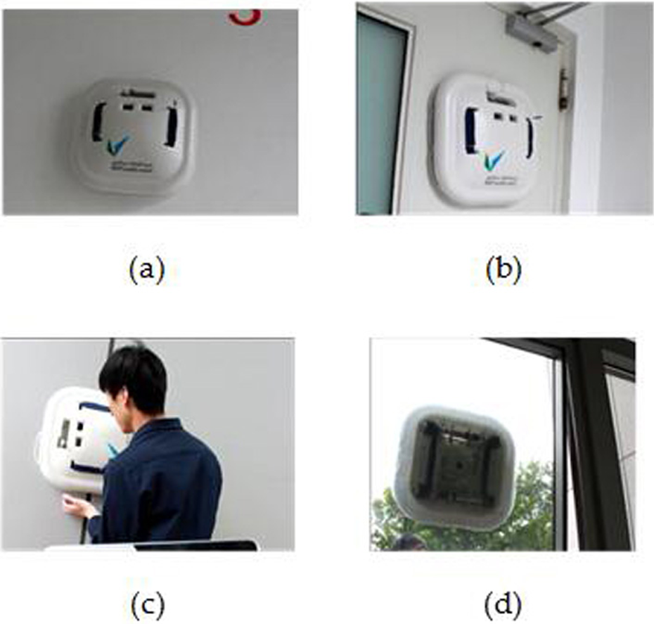
Test of adaptability to the wall surfaces: (a) painted wall, (b) varnished door, (c) iron plate with groove, and (d) plate-glass.
Camera experiment
The image quality of the video pictures captured in light place and dark place is clearly shown in Figure 22(a) and (b), respectively.

Video pictures: (a) in light place and (b) in dark place.
Sensor experiment
When the robot is adsorbed on the ground, the adsorption force can be changed by adjusting the fan voltage, and the fan voltage and output voltage of the differential pressure sensor at this time are recorded. The robot is torn from the ground along the vertical direction using electronic dynamometer. The maximum value of electrical dynamometer is known as pull force.
The sensor voltage can be converted to negative pressure according to the following relation
where,
The reduction formula between the pull force and the negative pressure can be expressed as

where, P the actual negative pressure, which is equivalent to
In this platform, the testing experiment with the differential pressure sensor MPXV5004G is carried out, and the result is demonstrated in Figure 23: the red and black line represent the testing data and the ideal data, respectively. The result shows that the value of negative pressure increases with the increase of the voltage of fan, and is closed to straight line. Therefore, the value of negative pressure can be regulated by regulating the voltage of fan.

Result of sensor test.
Antithrow experiment
Turnoff the fan and remove the adsorption after the robot is absorbed on the wall. Attitudes of the robot during free space operation are recorded. The testing heights are 0.5, 1, 1.5, and 2 m, as illustrated in Figure 24.

Attitudes of falling down: (a) initial attitudes of falling down and (b) final attitudes of falling down.
The falling protector, which acts at safety rope, can prevent the robot in a certain range when the robot is shaking and hits with the wall. In this process, all the parts are intact due to the compressive protection device. In the low-drop experiments, the robot can slide down along the wall first and then fall back. Almost all the parts are vulnerable to force impacts, but the damages are repairable. The safety drop height is 2 m. The performance test parameters of the robot have improved further compared with the same sort prototypes, as shown in Table 1.
The performance test parameters of the robot.

Conclusions
The article presents a kind of climbing robot platform with comprehensive protection device. The support frame with a simple structure that provides large space to install spare parts simplifies the whole structure of the climbing robot. The entire protection device, which includes safety rope, EVA shell, and airbag, offers some ideas for protection of the robot working at height. The stiffness model of the gasbag is established to adjust the airbag stiffness and improve the mechanical structure. The software can realize the data transmission between the host and lower computer reliably. The climbing robot can climb the wall successfully and transfer the video to the terminal device in real time. The platform has been testified by series of experiments to realize basic motor function and antithrow function. The platform provides a train of thought and inspiration for the antithrow design of climbing robot.
However, there are still flaws in some ways for improvement: the antithrow length and the rate of video transmission need to be improved.
Footnotes
Declaration of conflicting interests
The author declared no potential conflicts of interest with respect to the research, authorship, and/or publication of this article.
Funding
The author(s) received no financial support for the research, authorship, and/or publication of this article.