
Abstract
A robot must have a good understanding of the environment for autonomous navigation. Mobile robot using fixed laser range scanner can only detect obstacle on a plane level. This may cause important obstacles not to be appropriately detected. This will cause the map generated to be inaccurate and collision may actually occur during autonomous navigation. Microsoft Kinect is known to provide a low-cost 3-D data which can be used for mobile robot navigation. Many researchers focused on obstacles above ground level, and not negative obstacles such as holes or stairs. This article proposes the usage of Kinect sensor to detect negative obstacles and converts it into laser scan data. Positive obstacle is defined as the obstacle above the floor surface and negative obstacle is defined as the obstacle below the floor surface. Projection method is used to convert positive obstacle data from Kinect sensor to laser scan data. For negative obstacles detection, farthest point method and virtual floor projection method are used. The laser scan data from positive and negative obstacles are then combined to get an improved laser scan data, which includes all obstacles that are important for a robot to see. The negative obstacle detection methods are tested in simulated indoor environment and also experimental in a real environment. The simulation and experimental results have demonstrated the effectiveness of our proposed method to detect and map negative obstacles.
Introduction
An autonomous robot must have good understanding of the environment. Sensors are needed to measure physical quantity of the environment and convert it into data for robot to localize and navigate. A mobile robot system mostly uses laser range scanner as the input device to detect its environment. Although laser range scanner has a wide field of view and high accuracy, the feedback is limited to the plane level where the sensor is attached. Since it is limited to a single plane, a laser range scanner cannot detect all positive and negative obstacles.
Positive obstacle is defined as the obstacle above the floor surface and negative obstacle is defined as the obstacle below the floor surface. Figure 1 shows that a mobile robot with a fixed laser range scanner cannot detect obstacles that are lower than the laser beam and hence cannot detect the stairs going downward or negative obstacles such as holes.
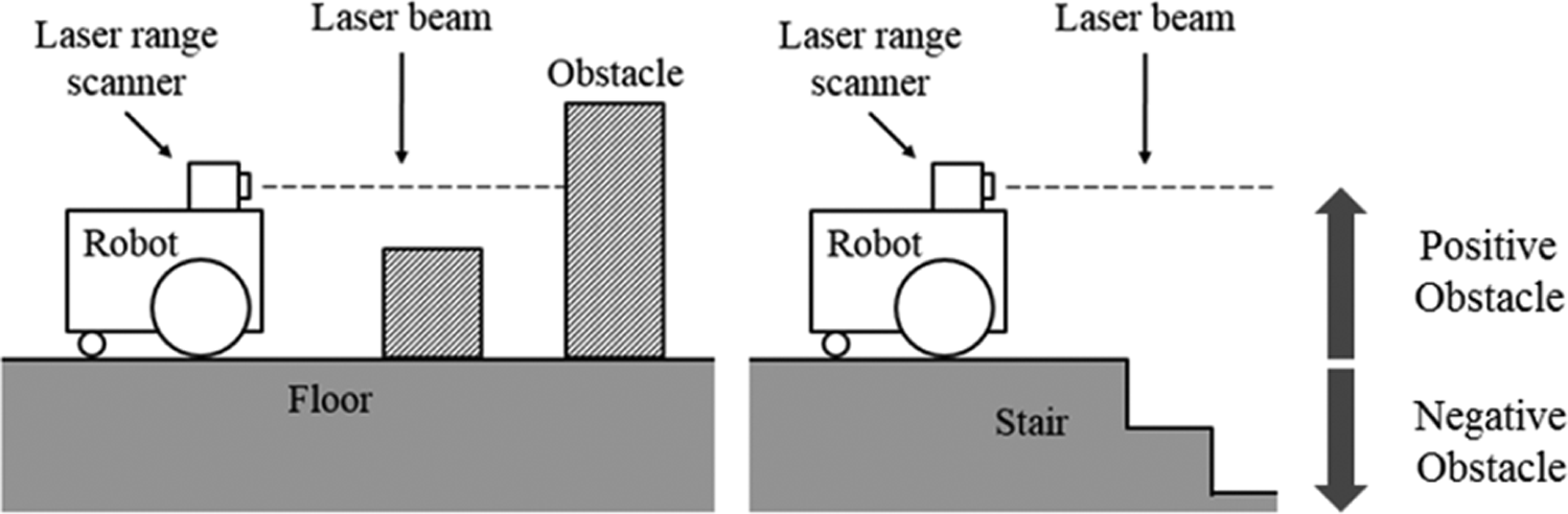
Robot using laser range scanner cannot detect low obstacle and stairs.
Since the sensor will only see a part of the object rather than the whole shape, it might map the obstacles inaccurately due to misinterpretation. 1 The misinterpreted obstacles may cause collision during autonomous navigation later. In a multistorey building, it is expected to have stairs going upward or downward. A robot with a laser range scanner that is placed horizontally cannot detect this downward stairs without additional sensors. The map generated using a fixed laser range scanner will not display obstacles that are not in the sensor’s view.
The launching of Microsoft Kinect sensor has attracted a lot of interest from robotics researchers. Researchers have been using Microsoft Kinect to replace laser range scanner for extracting obstacle data in indoor environments. 2,3 Although rotating laser range scanner using pan and tilt system can be used to obtain a 3-D view of the environment, Kinect sensor has more features, is cheaper, and is easier to use. Kinect sensor can provide both color image in RGB and depth image (D). 4 Depth image is an image that contains distance information relative to the camera position. Depth image can be processed to obtain useful information such as point cloud, object’s shape, and laser scan data.
This article presents a method used for detecting negative obstacle in indoor environment and then combines it with laser scan data from a laser range scanner. This article is an extension of our previous paper 5 which focuses on detecting positive obstacles. The proposed method is tested in both simulation and real environment to prove its effectiveness and to verify the results. The laser scan data can be used in 2-D simultaneous localization and mapping (SLAM) for building occupancy grid map of the environment. Occupancy grid map was introduced by Moravec and Elfes, 6 that represents environment using a grid, and each grid cell contains probability that the location is occupied by an obstacle. The map generated by this process can later be used by the robot for autonomous navigation in the same environment.
Related work
The 2-D SLAM technique has been used in many indoor robots that have fixed mounted laser range scanner. 2,7 Because of the wide field of view and long measurement distance, this SLAM process can work well in spacious indoor environments and can generate good floor plan map. The limitation of this system is that it cannot detect obstacles that are not in the sensor’s field of view, which is in 2-D plane, and cannot detect negative obstacles. If the laser range finder is placed horizontally like in many cases, obstacles which are lower or higher than the sensor level cannot be detected by the robot which may cause robot to collide with them. Pajaziti 8 has tested the 2-D SLAM system in simulated environment where all the obstacles are in sensor’s height. Zug et al. 9 have compared between laser range scanner and Kinect sensor for 2-D mapping, where they tested both in an environment where all obstacles are high enough for the laser scanner to detect. Although Kinect sensor was able to provide depth image, they only take the center row of the depth image data and convert it to laser scan data. The 3-D information from the depth image can be used to generate better laser scan data when there are obstacles of different heights.
Method to convert depth image from Kinect sensor to include all objects within the robot height in laser scan data is explained in Kamarudin et al. 10 Despite their method being able to detect obstacle better than normal laser scan, it cannot detect negative obstacles, such as holes in the floor. Negative obstacles are more dangerous to a mobile robot. If the robot falls from a high place, most probably it will either be damaged or end up either upside down or sideways, unable to move. To prevent this problem, some robots have additional sensors such as bumper sensor, ultrasonic sensor, and cliff sensor. Using these sensors, a robot needs to be close to the obstacle to detect it. This adds another complexity to the robot, as it needs to take into account the additional sensor value in the navigation process. If the robot can detect all obstacles using its primary sensor, the robot can avoid the obstacles without going closer to it. Kamarudin et al. have tested the performance of the Kinect sensor for 2-D SLAM techniques: Gmapping and Hector SLAM. 1 Gmapping process uses wheel odometry and visual odometry, while Hector SLAM uses visual odometry. From the test, Hector SLAM is faster than Gmapping, but it has no loop closing ability. They suggested that the usage of Kinect sensor for 2-D mapping can improve scan matching accuracy and provide reliable pose estimates. Rao–Blackwellized particle filters have been used to improve grid map. This approach uses a particle filter in which each particle carries an individual map of the environment. This method estimates the map and the trajectory of the robot, given observation and odometry measurement. The algorithm does not only update robot location based on odometry data but also based on the latest sensor view. 11
Peasley and Birchfield have used point cloud from Kinect sensor and projected them to the ground plane for obstacle detection and avoidance. 12 This method is suitable for autonomous navigation without map. The projected point cloud cannot be used in occupancy grid map because the map only takes laser scan data as input. Tomari et al. used Kinect sensor on an electric wheelchair to help user avoid positive and negative obstacles. 13 They filtered point cloud on floor surface to detect surface that can be traversable. They also used point cloud below floor surface and projected it to the virtual floor plane to mark as negative obstacle. For mapping process, Kinect sensor must be facing straight to the front and cannot be facing downward. If the sensor is facing downward and there is no obstacle in view, the robot cannot localize itself. Localization system requires obstacles’ features from the environment to function. Moreover, all obstacles data should be converted to laser scan data to make it compatible with occupancy grid map. Data from 3-D sensor must be processed to provide data in laser scan format.
Hartmann et al. used Kinect sensor with visual SLAM system to extract features from sensor view to calculate robot motion using visual odometry. 14 They focused on improving localization accuracy and real-time performance using Kinect 3-D data. The map generated by their system is an occupancy grid map. They used conventional method to generate laser scan data from Kinect depth image and only converted the center row of the Kinect sensor’s depth data to laser scan data. A lot of important obstacles might be ignored using this method.
Jo et al. have generated a voxel grid map of the environment from Kinect depth data. 15 In their research, they found out that the 3-D voxel map is difficult to make in real time. Robot using this 3-D SLAM system cannot be used to build the map autonomously because it cannot make the map in real time. They focused on improving the data in 2-D map because the map can be generated in real time, so that it can be used by autonomous robots. For a wheel-base robot that navigates on flat surface, 2-D navigation system is good enough for the robot. Moreover, the 2-D SLAM is faster than 3-D SLAM and it uses less computational process. Meanwhile, Hammer et al. have made a simple robot for 3-D mapping. Their robot still depends on 2-D map for basic navigation, and the 3-D map is generated off-line as using a 3-D map for basic navigation is too excessive. 16
Taking into consideration of all the literature, this research is aimed at generating a safer map for autonomous navigation of mobile robots through generating a comprehensive 2-D occupancy map for global path planning as the available 2-D SLAM systems only focused on detecting positive obstacles. At the time of this writing, there is still no research work reported that adds both negative and positive obstacles into the 2-D occupancy grid map. Although there are some research work done to detect negative obstacle for obstacle avoiding process, the obstacle avoiding process is for local path planning, not global path planning. In global path planning, the whole set of obstacles in the area has to be taken into consideration and the shortest path that avoids all obstacles can be planned. This research is conducted to prove that negative obstacles can be included into the occupancy grid map and are displayed as obstacles for the robot for global path planning.
System overview
The algorithm for this work is developed using robot operating system (ROS) platform. ROS is an open-source software framework or middle-ware for the robot software development. A ROS system consists of a number of independent nodes, each of which communicates with the other nodes using publish/subscribe messaging mode. ROS provides libraries and tools to help software developers create robot applications quickly and easily on a common platform. 17 The simulation work was done using Gazebo. Gazebo is an open source, multi-robot 3-D simulator for complex environments. This software is capable of simulating a population of robots, sensors, and objects. It generates both realistic sensor feedback and physically plausible interactions between objects. 18 The simulator was used to provide a controlled environment for better result comparison.
The Microsoft Kinect sensor is a vision sensor creates for Xbox 360 video gaming consoles that was launched on November 2010.
4
Kinect sensor was developed for controller-free video gaming, where the user plays video game without holding any controller. Development of Kinect sensor by Microsoft has made the task to get depth data easier. The low-cost Kinect sensor has the ability to detect color image, depth image, human movement, and stereoscopic sound. Depth image is a 3-D representation of environment in grayscale format; darker color is closer to the camera. This sensor detects depth using structured infrared pattern projection method. An infrared transmitter transmits a known light pattern and infrared camera detects the reflection. Based on the distortion in the infrared pattern, a Kinect sensor calculates the depth of an object from the camera. Kinect sensor uses depth image size of 640 × 480 pixels to represent a 3-D view of the environment. This sensor has
A lightweight mobile robot named TurtleBot is used for this project. Figure 2 shows the TurtleBot image from Gazebo simulator. TurtleBot is a small open-source indoor robot that uses a netbook as its main processor and Microsoft Kinect as its vision sensor. TurtleBot is specifically designed to be used with ROS, which is efficient and inexpensive. The built-in sensors in the robot are bumper sensor, cliff sensor, wheel drop sensor, wheels encoder, and gyro sensor. 19 TurtleBot is designed to work with multiple computers. For this work, the netbook on the robot is used only to read sensor data and control the robot’s movement. All heavy computation is done on another computer that has more processing power. Data between computers are transmitted through Wi-Fi network.

TurtleBot in Gazebo simulator.
Detecting negative obstacle
TurtleBot has three cliff sensors to detect cliff or hole in the floor surface. The robot will not drive off a cliff with a depth greater than 5 cm. 19 The TurtleBot driving system will overwrite other command and move backward when it has detected cliff. Nevertheless, TurtleBot can still fall if it moves too fast. Although cliff can be detected using the onboard cliff sensor, data from the sensor is not suitable to be used in the SLAM process because it only detects the cliff when the robot is close to it. SLAM processes require a sensor that can detect obstacles from a distance. Kinect sensor can be used to detect holes in the floor and make it as obstacle on the map generated by the SLAM process.
Kinect camera is mounted on a TurtleBot at a height of 30 cm from the floor surface. Point cloud on floor surface can be obtained easily by removing the point that is not on this horizontal level. Point cloud between 3 cm in height and this horizontal level are assumed as floor point cloud, as shown in Figure 3. Tolerance of 3 cm is considered because of the noise from a Kinect sensor reading.

Obstacle range used for getting floor point cloud.
It is difficult to detect the floor edge using the floor point cloud because the point cloud density near to a Kinect sensor is high, while the point cloud density far away from a Kinect sensor is low, as shown in Figure 4.

Point cloud top-down view from simulation.
The radius outlier removal filter, conditional removal filter, and statistical outlier remover filter have all been tested, but we were unable to determine the floor edge. Another problem with detecting negative obstacles such as holes in the floor point cloud is that the points are not organized; most algorithms developed to detect it are for organized point cloud.
Farthest point method
One of the solutions used to detect negative obstacle is to convert all the farthest point in floor point cloud to laser scan data. Farthest point method consists of two steps, as shown in Figure 5.

The processing step of farthest point method.
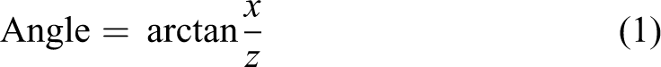
Using this method, the farthest floor limit can be detected. Each point in point cloud is in Cartesian coordinate, while the point in laser scan data is in polar coordinate. The conversion process is done using the following equation for every point in the point cloud.


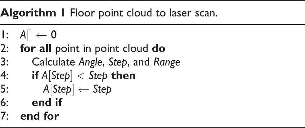
Algorithm 1 shows the pseudo code for this process. Array A contains the farthest point laser scan data from the projection laser scan data. Array A is initialized with maximum laser scan range value. Each point in the point cloud is used to calculate the angle, step, and range for that point. Then current value in array A in step angle is compared with range value. If the range value is smaller, it will replace the current value in the array. This process is repeated until all points are calculated. Each array element will have the shortest range from all point clouds in its step angle. Array A will contain laser scan data after the algorithm has been executed. Laser scan data using this method are called the farthest point laser scan. This method is suitable to detect floor edge on the side of the rooms, but it cannot detect holes in the middle of the floor. Figure 6 shows the illustration of this problem, it shows the top view of floor point cloud, colored in gray and laser scan in red.
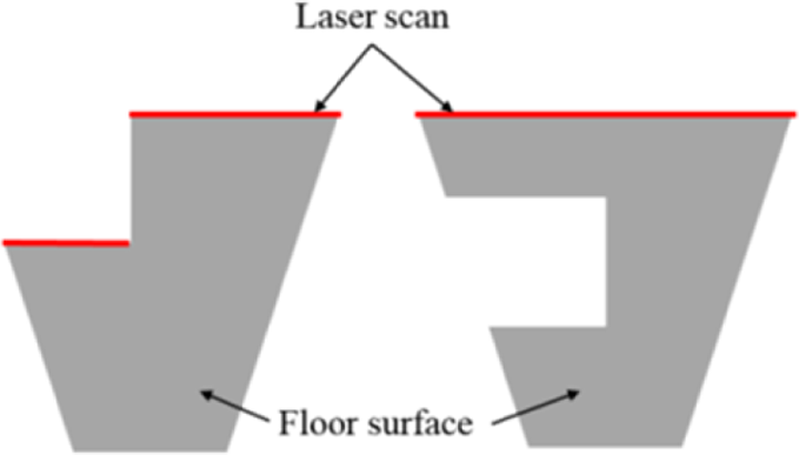
Illustration farthest point method problem.
On the left side, it shows that the floor has holes at the top end of the floor, where laser scan can detect the hole’s edge. On the right side, there are holes in the middle of floor point cloud, but the laser scan cannot detect the holes because it is not in the far end of the floor point cloud. Another method needs to be used to solve this problem.
Virtual floor projection method
Figure 7 shows processing step for virtual floor projection method.
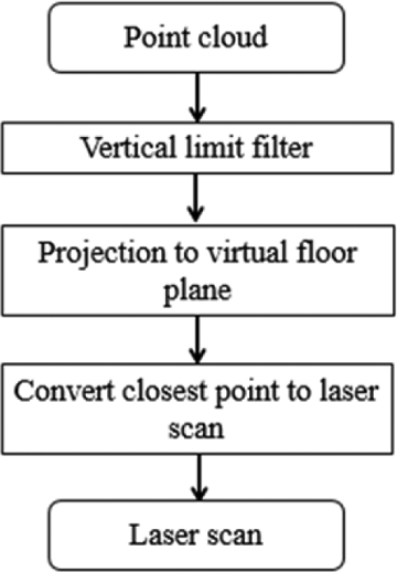
The processing step of virtual floor projection method.
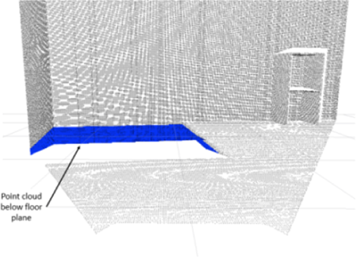
Another method that can be used to detect hole is by analyzing the point cloud that is located below floor level. Using the point cloud coordinate, the coordinates where the point cloud should be on the floor level can be calculated. Figure 8 shows the point cloud below floor surface colored in blue and point cloud on the virtual floor plane colored in red.

Point cloud below floor surface are projected to floor surface.
This method assumes that there is some thickness to the floor that can be seen from the side. The conversion between the old point coordinate, a point below floor surface and the new point coordinate, a point on the floor surface is shown in Figures 9 and 10.

Side views of connection between old point and new point.

Top views of connection between old point and new point.
The

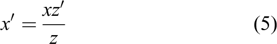
After the points are converted to points on the floor surface, the points are represented as an obstacle in the laser scan data. This method can detect holes in the middle of the room, provided it can detect the surface below the floor level. Algorithm 2 shows how the conversion is done.
Array B is the virtual floor projection laser scans. Firstly, it is initialized to a maximum range value. Then the new point cloud coordinate values are calculated using equations (4) and (5). After that, angle, step, and range are calculated using the new coordinate. Then the smallest range is saved into array B.

Combining negative obstacle laser scan data
Both hole detecting methods discussed before this have their own advantages and disadvantages. Both methods can be combined to detect holes better. The combination is done by taking the closest point in each laser scan and generating a new laser scan from it. The combination process is shown in algorithm 3. Array C is initialized with value from array A, which is the floor laser scan data. Then respective value in array C and array B is compared to get the smallest value.
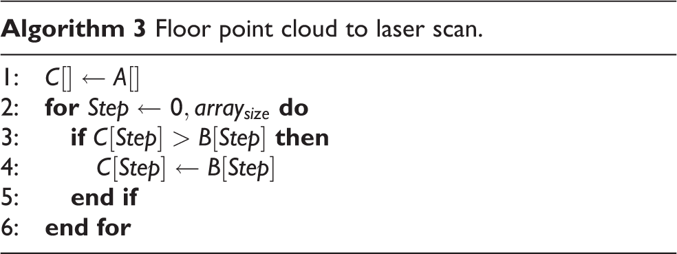
Finally, both positive laser scan data and negative laser scan data are combined using algorithm 3. In the final laser scan data, all obstacles are visible in the map.
Experiment
We first tested the entire step explained previously in Gazebo simulated environment. Figure 11 shows the color image from Kinect sensor inside simulated environment that has been used for testing negative obstacle detection method. This environment has a 2 × 2 m hole in it.
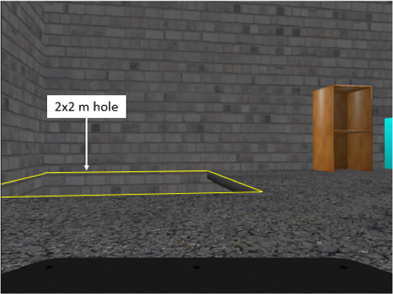
Color image of the simulated environment.
Farthest point method laser scans
Figure 12 shows the environment point cloud in black color and floor point cloud in blue color. The vertical limit filter is used to extract floor point cloud. It takes all points in the floor range as explained in Figure 3. Point cloud on the wall surface within this range is also included in the floor point cloud as the outer boundaries. The laser scan data using the farthest point method are shown in Figure 13.

Floor point cloud filtered.

Farthest point laser scans from simulated environment.
From Figure 13, it can be seen that the laser scans were not able to detect the nearer hole’s edge, because the point cloud at the wall is the farthest point in that direction.
Next, the method is tested in a simulated environment where the wall behind is removed. This is to test the condition where the negative obstacle is large. Color image from Kinect sensor for this condition is shown in Figure 14. Figure 15 shows the point cloud of the environment and the floor point cloud. The floor laser scan result is shown in Figure 16.

Color image of simulated environment when wall is removed.

The filtered floor point cloud.

Farthest point laser scans from simulated environment when wall is removed.
It is observed that some parts of the hole’s edge are visible in the laser scan data. This shows that the edge of the floor can be detected using this method only if there is no other point after the edge. It is also observed that the laser scans in the top right region could not correctly display the floor edge compared to Figure 13. This happens because both Kinect’s resolution and point cloud density decreased the further away the point is from Kinect sensor.
Virtual floor projection method laser scans
Figure 17 shows the point cloud from simulated environment which includes point cloud below floor plane surface. The vertical limit filter is used to get the point cloud below the floor surface. The point cloud below the floor plane is then projected to a virtual floor plane. The closest point cloud on the virtual floor planes in each angle is converted into laser scan data, as shown in the virtual floor projection laser scan data in Figure 18.
Filtered point cloud below floor surface in simulated environment.

Virtual floor projection laser scans data.
It can be observed that only the floor edge or the holes are visible in the laser scan data. The wall behind and other objects are not visible in the laser scan data. Figures 19 and 20 show the same process for simulated environment where the wall is removed.

Point cloud below floor plane.

Virtual floor projection laser scans data.
It can be observed that not many point clouds below the floor are present in the laser scan data and only some part of the hole is visible. The laser on the right part of the hole in Figure 20 does not show the right location of the edge because the floor is quite thin. When the point below the floor plane is converted to floor plane, the point is still near to the right side edge, not at the closest edge. Nevertheless, this situation can be ignored as the laser scan still display the hole shape correctly.
Combining negative obstacle lasers scan
Figures 21 and 22 show the combination of both negative obstacle laser scan data for simulated environment and simulated environment where wall is removed.

Combination of both negative obstacle laser scan.

Combination of both negative obstacle laser scan for simulated environment when wall is removed.
Laser scan data in Figure 21 are able to display the hole as an obstacle and it detects the end of floor surface where there is no hole in that area. For environment where the wall is removed, the scan can detect the edge of the floor except for the right edge of the hole as shown in Figure 22. This is not a big problem, as the scan is still close to the edge and scan matching process can still work fine.
Real environment mapping test
A mapping process has been done in real environment to verify that the process explained above can be used in real environment. Figure 23 shows the location that was selected for testing.

Location used for testing mapping process.
This location was selected as it has both positive and negative obstacles. There is a railing bar that is widely spaced and stairs going to the floor below. Figure 24 shows the map generated using the projected laser scan method.
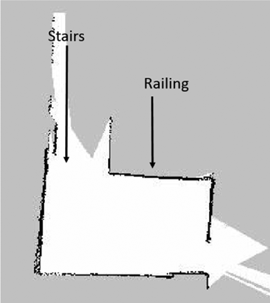
Map real environment using projection method.
It can be observed that the positive obstacle which is the railing is visible in the map. This can prevent the mobile robot using autonomous path planning from going near the area. As expected, the stairs are not present in the map.
The map generated using laser scan combined from the projection laser scan and negative obstacle laser scan is shown in Figure 25. The white grid in the map shows the accessible area to the robot. Some of the stair area is marked as empty grid because of the tolerance used in the hole detecting algorithm. Compared to the map in Figure 24, this map is better, as it marks the accessible area limit by assuming it as an obstacle. This can prevent robot from colliding with the railing or falling from the stairs. The wall on the left appears thick due to the noisy Kinect sensor reading. The scattered black points on top of the map are also due to noise.

Map real environment using projection laser scan and negative obstacle laser scan.
Conclusion
In this article, we presented an approach to detect negative obstacles using Kinect sensor and generate a more comprehensive laser scan data when combined with the positive obstacles. Our methods are able to detect negative obstacle which is missing in a normal laser scan data. This will make it possible for a mobile robot to move autonomously and avoiding not only positive obstacles but negative obstacles as well. The method is validated through simulated environment as well as real experiment.
Footnotes
Author’s note
This article is a revised and expanded version of an article entitled “Improvement of the 2D SLAM system using Kinect sensor for indoor mapping” 5 presented at SCIS and ISIS 2014, Kitakyushu, Japan, 3–6 December, 2014.
Declaration of conflicting interests
The author(s) declared no potential conflicts of interest with respect to the research, authorship, and/or publication of this article.
Funding
The author(s) disclosed receipt of the following financial support for the research, authorship, and/or publication of this article: This study was funded by Ministry of Higher Education Malaysia through the FRGS grant scheme and Universiti Tenaga Nasional through its BOLD grant.