
Abstract
Snake-like robots can perform various types of locomotion in the complex environments. In this article, a novel two-layered central pattern generator-based controller is proposed for controlling snake-like robots. To adapt to rough terrain, snake-like robots can dynamically adjust their locomotion through modulating the control parameters of the central pattern generator-based controller based on the sensory feedback. When the parameters are modulated through the step function, the outputs of the central pattern generator-based controller may be unsmooth or discontinuous during the transition process. This will result in stiff and flexible impulses on the motors and gearboxes. In this article, the curvilinear continuity is used to evaluate the continuity degree of the outputs of the central pattern generator-based controller. In order to avoid the damage to the joint motors, two sigmoid transition approaches are proposed. First, a sigmoid parametric modulation method for the central pattern generator-based controller is proposed to eliminate the abrupt changes in the control signals of the joint motors. Second, a sigmoid start-up method is presented to improve the motion efficiency of the snake-like robot. The simulation results of the snake-like robot show that the outputs of the central pattern generator-based controller transit smoothly with the proposed sigmoid parametric modulation method. The snake-like robot can perform a soft start when the sigmoid start-up method is applied. The results demonstrate that the central pattern generator-based controller and the two proposed sigmoid transition approaches are effective.
Keywords
Introduction
Biological snakes can perform various gaits to traverse through complex environments, that is, rectilinear motion, serpentine motion and sidewinding motion. The serpentine motion is the most typical and efficient locomotion. Hirose et al. 1 described the serpentine locomotion as a continuous serpenoid curve. From the view of muscle characteristics of biological snakes, Ma presented a serpentine curve which was similar with serpenoid curve in. 2 Based on the analysis, the relative joints of the snake-like robots are controlled by the sinusoidal functions. Inspired by the locomotion of natural snakes, lots of snake-like robots have been developed. Snake-like robots are hyper redundant robots with many degrees of freedom (DOF). The proposed snake-like robots are commonly applied to operate in the unknown environments, such as search-and-rescue in ruins of collapsed buildings. 3 –5
The intelligent locomotion control approaches for robots include the analytical approaches, neural networks and central pattern generators (CPGs). 6 Animals have evolved over millions of years and could easily adapt to rough terrain. The locomotion controllers of robots can take inspiration from the control mechanism of animals. The CPG is a neural network of neurons capable of generating rhythmic pattern outputs spontaneously. The rhythmic signals are utilized to control and coordinate each joint simultaneously. 7 –9 The CPG-based controller has already been applied to the control of humanoid robots, 10 quadruped robots, 11 fish robots, 12 salamander robots 13 and robotic manta rays 14 and so on. The CPG-based controller has also been utilized to control the locomotion of snake-like robots. A Kuramoto oscillator-based CPG is proposed by Crespi and Ijspeert. 15 The oscillators of the CPG are mutually coupled. Each joint of the snake-like robot is controlled by two oscillators. Nor et al. 16 simplify the topology of CPG through unidirectional coupling relation. Wu 17 and Lu 18 both proposed CPG based on the Matsuoka model. The difference between the two CPGs was the coupling relation of neurons. The anterior one uses the mutual coupling neurons to control each joint of the snake-like robot. The latter one uses three cyclic coupling neurons to control two joints of the snake-like robot.
To adapt to complex terrain, snake-like robots switch motion modes through modulating the controlling parameters of the CPG-based controller. 19 Plenty of researches on how to modulate the parameters of the CPG-based controller online have been carried out. The control parameters are determined by a mapping function of the descending input signal and the sensory feedback. 20,21 The mapping functions can be linear or nonlinear. As modulating the control parameters, the outputs of the CPG-based controller will converge to the desired trajectory. The outputs in the transition process are generally regarded as smooth when the trajectories of the motors are continuous. 22,23
The biological systems of snakes are mechanical systems and have dynamic thresholds, that is, velocity, acceleration, jerk and so on. The unsmooth motion may lead to physical damage, such as tearing of muscles or breaking of bones when the dynamic thresholds are exceeded. 24 The snake-like robots are also mechanical systems composed of joint motors and shell frames. If the dynamic tolerance levels exceed, these components of the mechanical system may fail either. For wheeled robots 25 and the robotic manipulator, 26 the common problem is the jerk control of the actuators. To obtain smooth profiles of the actuators, the locomotion controller should keep the joint jerk within the bounds for continuous acceleration. 27 Engineers have recognized that the main benefit of minimizing jerk is to avoid the abrupt motion and consequently limit the vibrations of the robots.
The central nervous systems of animals do not apparently minimize the jerk of motions. The control parameters changed abruptly can lead to unsmooth transition of the motion. Optimizing transition movement by minimizing jerk is beneficial by which it can reduce the stress on the mechanical components of the robot and increase the stability. Ijspeert et al. 13 applied a critically damped equation to control the amplitude and offset of the joint motion. Li et al. 10 used a simple exponential function to control transition process of a humanoid robot. Chen et al. 28 proposed a kind of three chained first-order filters to control the phase bias of the CPG. However, all of them did not discuss the smooth degree of the transition motion. Nor et al. 29 proposed a linear phase transition function for the CPG. In addition, the authors presented a criterion of smoothness of the movement. The smoothness of the output signals of the CPG is discussed from the view of the mathematical analysis.
In this article, a novel two-layered CPG-based controller and the sigmoid transition approaches are proposed for a planar snake-like robot. The rest of this article is organized as follows. The kinematic model of the serpentine locomotion of the snake-like robot is presented in second section. The third section introduces the mathematical model, the coupling topology and the parametric analysis of the CPG-based controller. In fourth section, the continuity criterion of the output signal of the CPG-base controller, the sigmoid parametric modulation approach and the sigmoid start-up method are illustrated. The simulation results of the snake-like robot and corresponding analysis are presented in the fifth section. Concluding remarks and future works are given in sixth section.
Locomotion of snake-like robot
As shown in Figure 1(a), the serpentine locomotion is the most typical locomotion observed in almost all the biological snakes. Each part of the body performs a similar track. Hirose et al. 1 described the serpentine locomotion as a continuous serpenoid curve of which the expression is given by

The serpentine locomotion. (a) The snake in nature. (b) The body shape of the snake-like robot approximates the serpenoid curve.

where s is the infinitesimal segment along the body of the snake-like robot, a is the winding angle, b is the number of periods in a length and c is the direction of the movement of the robot.
However, the snake-like robot only has N segments which are much less than the natural snakes. Figure 1(b) gives the discrete model which is applied to approximate the continuous serpenoid curve. 30 The total length of the N segments is set as 1. The continuous serpenoid curve is approximated by N segments. The joint coordinates of the snake-like robot is donated as (xi , yi ) where (i = 0, 1, 2,…, N). The coordinate of each joint is given by

Each relative angle between the segment and the x-axis is calculated by

where ω is the angular frequency, the phase bias β = b, b = 2πK/N, and the offset γ = -c/N. ψi is the angle between the ith segment and the x-axis. K is the number of periods in the serpenoid curve.
The relative angle between the two segments can be calculated by

where the amplitude α = −2asin(b/2 N). φi is the angle of the ith joint.
The parameters a, b and c determine the shape of the serpenoid curve realized by the snake-like robot. Diverse locomotion of the snake-like robot can be performed by modulating the three parameters. Figure 2 illustrates the impacts of each parameter on the shape of the serpenoid curve. The parameter a only determines the amplitude of the curve. The parameter b determines the amplitude and cycles of the curve. The parameter c determines the offset of the curve. In addition, the parameter ω specifies the velocity of the serpenoid wave propagates along its body axis. The snake-like robot could adjust its direction, velocity and amplitude of the body shape to adapt to complex environments. For example, the snake-like robot can perform the turning motion through modulating the offset, the phase and the amplitude of each joint angle.

The shape of the serpenoid curve changes with modulating the parameters a, b, and c.
Two-layered CPG-based controller
Model and coupling topology
The architecture of the proposed CPG is divided into the rhythm generation (RG) layer and the motor neuron (MN) layer. The RG layer provides the signals which are the clocking drivers of the CPG. The MN layer is directly used to control the objects (muscles or motors) based on the signals of the RG layer.
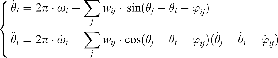
The Kuramoto oscillator is applied to model the neurons in the RG layer of the CPG for the snake-like robot. The Kuramoto oscillator, which is one of the most basic models widely used to study the neurobiological activity, describes how a group of interacting neurons produce the synchronized behaviours. The model of the neurons in the RG layer is as follows

where the parameter θi is the state variable which stands for the phase of each neuron. Parameters wij and ϕij are respectively the coupling weight and phase bias between the ith and jth neurons. The two parameters determine how the jth neuron affects the ith neuron. The parameter ωi is the intrinsic frequency of each oscillator. To simplify the model of the CPG, the parameters wij and ωi are set as equal for all neurons in the RG layer.
The output signals cannot be directly used to control the joints of the snake-like robot. Therefore, the neurons in the MN layer are used to reshape the output signals of the RG layer. As presented in the second section, the joint control signals of the snake-like robot are based on the sinusoidal function. Therefore, the model of the neurons in the MN layer is given by

where ri and xi are the desired amplitude and offset, respectively, and ϕi is the control signal which drives the corresponding joint of the snake-like robot.
The coupling topology and the control parameters have great impacts on the outputs of the CPG. As shown in Figure 3, the coupling direction between two neurons in the RG layer can be unidirectional or bidirectional. In order to confirm the coupling topology of the RG layer, a numeric analysis has been done, and the results are presented in Figure 4. Figure 4(a) and (b) shows the different coupling directions of three neurons in the RG layer. The time of the unidirectional coupling neurons is 6.26 s, and the time of the bidirectional coupling neurons is 4.96 s. Therefore, the synchronization rate of the unidirectional coupling topology is slower than the one of bidirectional coupling. The synchronization rate determines the motion response of the snake-like robot. Therefore, a mutual coupling scheme of the neurons in the RG layer is applied to control the snake-like robots.
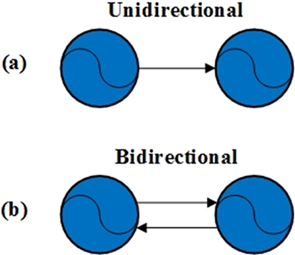
The coupling relations of the two neurons in the RG layer of the proposed CPG. CPG: central pattern generator; RG: rhythm generation.

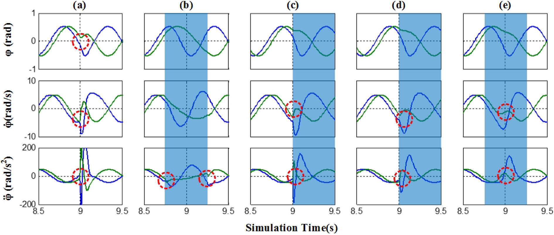
The impacts of the coupling relation and the parameters on the output of the two-layered CPG-based controller. (a) The coupling direction is unidirectional. (b) to (e) The coupling direction is bidirectional. The other parameters are set as follows: (a) and (b) wij = 2, ωi = 0.1, ϕij = π/4; (c) wij = 4, ωi = 0.1, ϕij = π/4; (d) wij = 2, ωi = 0.1, ϕij = π/3; (e) wij = 2, ωi = 0.15, ϕij = π/4. CPG: central pattern generator.
The output signals of the CPG can be regulated in different ways to response to perceptual inputs. Therefore, the effects of the coupling weight, the phase bias and the frequency have also been analysed. Figure 4(c) depicts that the synchronization time of the neurons is evidently shortened when the coupling weight wij is doubled. Therefore, the coupling weight has great impact on the synchronization rate. Figure 4(d) presents that the phase relation of the neurons is determined by the phase bias ϕij , and the synchronization rate is slightly affected by the phase bias. As shown in Figure 4(e), the frequency ωi only determines the period of the outputs of the neurons.
To sum up, the structure of the CPG-based controller is composed of a two-layered CPG and a PID controller which are presented in Figure 5. The topology of the neurons in the RG layer is chain-typed, and the adjacent neurons are mutually coupled. The angle positions of the joints of the snake-like robot are controlled by the MN neuron. The joint motors are controlled by a simple PID controller based on the output signals of the MN layers.

The proposed two-layered CPG-based controller for the snake-like robot. The blue circle represents the neurons in the RG layer and the light yellow rhombus represents the neurons in the MN layer. CPG: central pattern generator; RG: rhythm generation.
Parametric analysis
Equations (4) to (6) give the control functions of each joint which are derived from the discrete serpenoid curve. The amplitude (α and ri ), the frequency (ω and ωi ), the phase bias (β and ϕij ) and the offset (γ and xi ) are used to shape the body curve and regulate the locomotion of snake-like robots. The control parameters of the CPG-based controller are modulated dynamically to obtain the desired locomotion.
Figure 6 shows the variation tendency of the outputs of the CPG-based controller of which the frequency ωi , the phase bias ϕij , the amplitude ri and the offset xi are modulated through the step function. The outputs of the controller are applied to control the angular position of each joint of the snake-like robot. Therefore, the first-order differential of the outputs of the CPG-based controller is the angular velocity of the joint motors. The second-order differential of the outputs are the angular acceleration of the joint motors and the angular jerk is the third-order differential of the outputs. As shown in Figure 6, the outputs of the CPG-based controller undergo a transition stage. In Figure 6(a) and (b), the frequency ωi and the phase bias ϕij of the neurons are modulated through the step function. The angular position of each joint is slightly changed at the transition points which are marked by the red dash circle in the figures. However, the angular velocity and the angular acceleration of the joints change abruptly. In Figure 6(c) and (d), it can be seen that the angular velocity and angular acceleration of the joints also change abruptly when the amplitude ri and the offset xi are modulated by the step function. Moreover, the angular positions of each joint of the snake-like robot have also discontinuity at the transition points.

The outputs of the CPG-based controller when the frequency ωi (a), the phase bias ϕij (b), the amplitude ri (c) and the offset xi (d) are modulated. The red circle represents the transition points of the output curves of the CPG-based controller. CPG: central pattern generator.
As known to all, excessive position and velocity of the motion profile will lead to stiff impulse of the joint motors, and the excessive acceleration will result in flexible impulse of the joint motor. The stiff impulse will damage the motors and the gearboxes of the snake-like robot. In addition, the flexible impulse will result in unstable movement of the snake-like robot. Therefore, the motion of the joint motor should be continuous and smooth.
Sigmoid transition approach
The outputs of the CPG-based controller are directly applied to control each joint of the snake-like robot. It means that the trajectories of the joint motors are determined by the outputs of the CPG-based controller. Therefore, the continuity and smoothness of the curves of the output should be considered.
Continuity criterion of the curves
As shown in Figure 7, the curve of the output of the CPG-based controller changes from ϕa (t) to ϕb (t) when the control parameters are modulated at the time t 1. The smoothness degree at the transition point of two curves is measured by the curve continuity, that is, the parametric continuity Ck and the geometric continuity Gk . The parametric continuity Ck describes the differentiability of the parametric representation of the curves of the outputs of the CPG-based controller. The Ck continuity means that k-order continuous derivatives of the curvilinear equation exist at the transition point. The parametric continuity of the curve ϕ(t) is given by

The curve continuity of the outputs of the CPG-based controller. (a) The output of the controller changes from ϕa
(t) to ϕb
(t) at time t
1. (b) The difference between the parametric continuity and the geometric continuity.
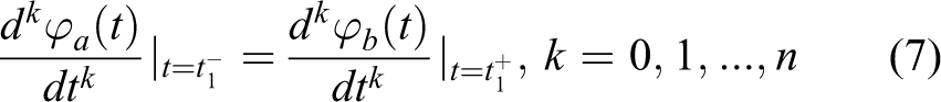
where t 1 is the transition time when the control parameters are modulated.
The geometric continuity can also be used to evaluate the smoothness degree of the curve. Figure 7(b) shows that the curves ϕa
(t) and ϕb
1(t) that touch each other at the transition point only satisfy C
0 and G
0 continuity. It means that the definition of C
0 and G
0 continuity is equivalent. The curves ϕa
(t), ϕb
2(t) and ϕb
3(t) satisfy C
0 and G
0 continuity. The tangent vectors of the curves ϕa
(t), ϕb
2(t) and ϕb
3(t) are, respectively, denoted as
The four typical continuity levels of the curves are described in Table 1. To avoid the stiff and flexible impulses, the curves of the output signals of the CPG-based controller should have the second-order derivatives. In other words, the continuity constraints of the curves of the output signals of the CPG-based controller strictly satisfy C 2 continuity. All the control parameters of the CPG-based controller are set as a function of t. The expressions of the curves of the output signals of the CPG-based controller are calculated by
Continuity of the curve.


where
The outputs θi of the RG layer and the control parameters ri and xi should satisfy C2 continuity. The control parameters ωi and ϕij should satisfy C1 continuity. When the four control parameters are modulated through the step function, the first-order differential of the parameter at the transition point is an impulse function. This induces the discontinuity of the curves of the output signals of the CPG-based controller. The corresponding results are presented in Figure 6. In order to avoid the discontinuity, a sigmoid parametric modulation method is proposed to improve the continuity of the output signals of the CPG-based controller.
Sigmoid parametric modulation method
Plenty of parametric modulation methods have been proposed in the last study. For example, Zhou et al. proposed a locomotion controller for a biomimetic underwater robot with fin propulsion. 14 The movement direction of the underwater robot is controlled by the phase difference of two fins. In addition, the phase differences are determined by a sigmoid function which is given by

where the sensory feedback is integrated through introducing the variable q, ϕd,L and ϕd,R are, respectively, the phases of the left and right fins; τ is the positive constant and a is a constant which determines the midpoint of the sigmoid function. The phase bias of the two fins can only change within the range of ±ϕd .
Matos et al. proposed a brainstem-like modulation approach for the gait transition in a quadruped robot. 20 The activities of the limb-CPGs based on the Hopf oscillator are regulated by a given modulatory drive signal. The phase bias, amplitude and frequency of the CPG are expressed by a linear piecewise function of the drive signals. The corresponding function are given by

where x is the modulatory drive signal, k 1 and k 2 are both the sensory thresholds, m 1 and m 2 are the two ultimate values of the modulated parameters, respectively.
If the drive signal (q or x) is modulated through the step function, the control parameter also changes abruptly. The previous two adjusting methods can both fall into step function-based transition method.
Ijspeert et al. proposed a CPG based on the amplitude-controlled phase oscillator. 13 The amplitude and the offset of the oscillators are controlled through a second-order damped function-based transition method. The equation of the second-order damped function is given by
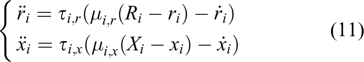
where the parameters τi,j and μi,j are the positive constants which determine the rise times of the amplitude and the offset to the desired values Ri and Xi , respectively.
The differential equation (11) is critically damped when the parameters satisfy μi,x/r = τi,x/r/4. Even if the amplitude and offset are changed abruptly, the output signals of the oscillators will progressively converge to the desired value.
Equation (11) can be simplified down to a first-order differential equation. Li et al. 10 applied the first-order low-pass filter-based transition method to control transition process of a humanoid robot. The equation of the first-order low-pass filter is given by

where the parameters ai and bi are the positive constants which determine the rise times, and Ri and Xi are respectively, the desired values of the amplitude and offset.
Nor et al. proposed a CPG-based body shape control method for a snake-like robot. 29 The body shape is regulated by modulating the phase bias of the CPG. To avoid the abrupt changes of joint angles, the authors applied a linear piecewise function-based transition method to control the change of the phase bias between two values. The equation of the linear piecewise function is given by

where ui is the initial value of the modulated control parameter, and ui+ 1 is the target value of the modulated control parameter, t 1 is the transition time and τ is the transition interval.
As shown in Figures 8(a) to (d) and 9(a) to (d), the amplitude and phase bias of the neurons of the CPG are modulated through the four different transition methods, that is, the step function-based transition method, the linear piecewise function-based transition method, the second-order damped function-based transition methods and the first-order low-pass filter-based transition method. In order to compare the performance of the smooth modulation methods, the transition intervals of the three latter methods are set as equal. As shown in Figures 8(a) and 9(a), the first-order and second-order differential of the outputs of the CPG are discontinuous when the amplitude and phase bias are modulated through the step function-based transition method. As shown in Figures 8(b) and 9(b), the linear changes of the amplitude and phase bias induce that the curves of the outputs have C1 continuity. The second-order differential of the outputs are discontinuous. This will lead to flexible impulse of the joint motor at the transition point. As shown in Figures 8(c) and (d) and 9(c) and (d), the first-order low-pass filter and second-order damped function-based transition methods make the curves of the outputs have C1 continuity. This will also lead to stiff impulse of the joint motor. It can be seen that the performance of the linear piecewise function-based transition method is the best among the four methods. However, the linear piecewise function based-transition method has bad performance in modulating the amplitude.

The amplitude of the motor neurons of the CPG is modulated through different approaches. (a) The amplitude is changed through a step function. (b) The amplitude is changed through a linear piecewise function. (c) The amplitude is changed through a first-order low-pass filter. (d) The amplitude is changed through a second-order damped function. (e) The amplitude is changed through a sigmoid function. CPG: central pattern generator.
The phase of the neurons in the RG layer of the CPG is modulated through different methods. (a) The phase is changed through a step function. (b) The phase is changed through a linear piecewise function. (c) The phase is changed through a first-order low-pass filter. (d) The phase is changed through a second-order damped function. (e) The phase is changed through a sigmoid function. CPG: central pattern generator; RG: rhythm generation.
In this article, a sigmoid parametric modulation method is proposed to improve the smoothness level of the outputs of the CPG-based controller. This method is similar with the linear piecewise function-based transition method. The difference is that the linear piecewise function is replaced by a sigmoid function in the proposed modulation method. The expression of the proposed sigmoid function is given by

where ui and ui+ 1 are, respectively, the initial and target values of the parameters. t 1 is the transition time, and τ and a are, respectively, the steepness and midpoint of the sigmoid function.
As shown in Figures 8(e) and 9(e), the sigmoid based-transition method makes the curves of the outputs smoother than the other four motioned methods. The continuity level of the curves of the outputs of the CPG-based controller is C2 continuity.
Sigmoid start-up method
As shown in Figure 10, the snake-like robot herein considered is composed of 9 joints and 10 links. The initial state of the snake-like robot is commonly a straight line which is presented in Figure 10(a). Each joint of the snake-like robot is directly controlled by the outputs of the CPG-based controller. The stable state of the snake-like robot is shown in Figure 10(b). Four numerical simulations of the CPG-based controller have been done to analyse the outputs of the CPG-based controller. The simulation results are illustrated in Figure 11. It can be seen that all joint angles change from zero to positive values during the unsynchronized stage of the CPG-based controller. The stages are marked by the blue orthogons in Figure 11. The output signals of the CPG-based controller in the unsynchronized stage do not satisfy the constraints of the serpenoid curve. All joints of the snake-like robot bend to the same direction. The corresponding state of the snake-like robot is presented in Figure 10(c). The energy consumption of the joint motors will increase in the stage, and the movement direction of the snake-like robot will also change. To avoid the direction deviation, the output signals of the CPG-based controller for the snake-like robot should be masked in the unsynchronized stage.

The three states of the snake-like robot. (a) Initial state. (b) Stable state. (c) Transitional state.

The outputs of the CPG-based controller for controlling the snake-like robot. (a) wij = 5, ωi = 0.5 and ϕij = 2π/9; (b) wij = 20, ωi = 0.5 and ϕij = 2π/9; (c) wij = 5, ωi = 0.25 and ϕij = 2π/9; (d) wi j = 5, ωi = 0.25 and ϕij = π/9. CPG: central pattern generator.
Ye et al. 31 proposed a method which make the joint angles of the snake-like robot gradually transit from the initial state to the stable state. However, the signals of each joint in the unsynchronized stage are not masked by the proposed method in the study by Ye et al. 31 This will still result in direction deviation. In this article, a sigmoid start-up method is proposed for controlling the snake-like robot during the start-up period. The sigmoid function is applied to mask the initial state of the CPG-based controller and make the signals of each joint change gradually. The model of the proposed CPG-based controller is given by

where the parameter t syn is the midpoint of the sigmoid function.
As shown in Figure 12, the outputs of the CPG-based controller synchronize at the time t = 3.88 s. During the start-up period, the outputs of the CPG-based controller gradually converge to the stable signals which satisfy the constraint condition of the serpenoid curve.
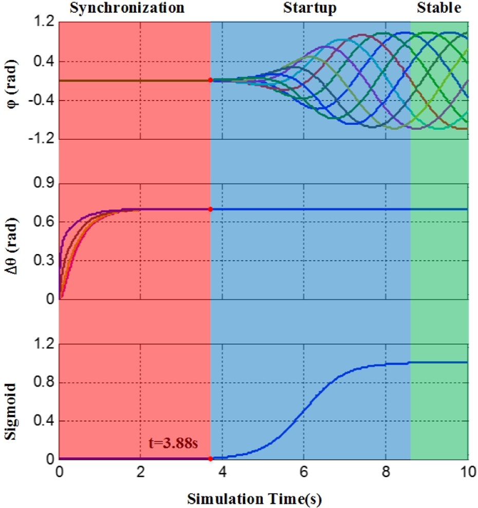
The outputs of the CPG-based controller are masked by the sigmoid function. CPG: central pattern generator.
Simulation results and discussion
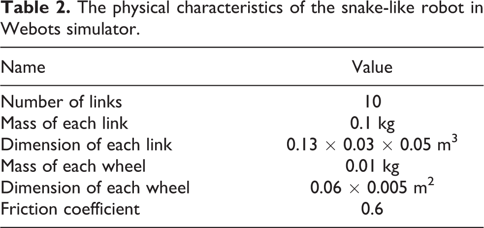
A simple planar snake-like robot is built in the Webots. The characteristics of the snake-like robot are given in Table 2. The snake-like robot is composed of 10 segments. The total length of the robot is 1.3 m. First, the locomotion of the snake-like robot is simulated without or with the proposed sigmoid parametric modulation approach and the sigmoid start-up method. Second, the performance comparisons of the four different transition methods have been evaluated and discussed.
The physical characteristics of the snake-like robot in Webots simulator.
Snake-like robot with/without smooth control
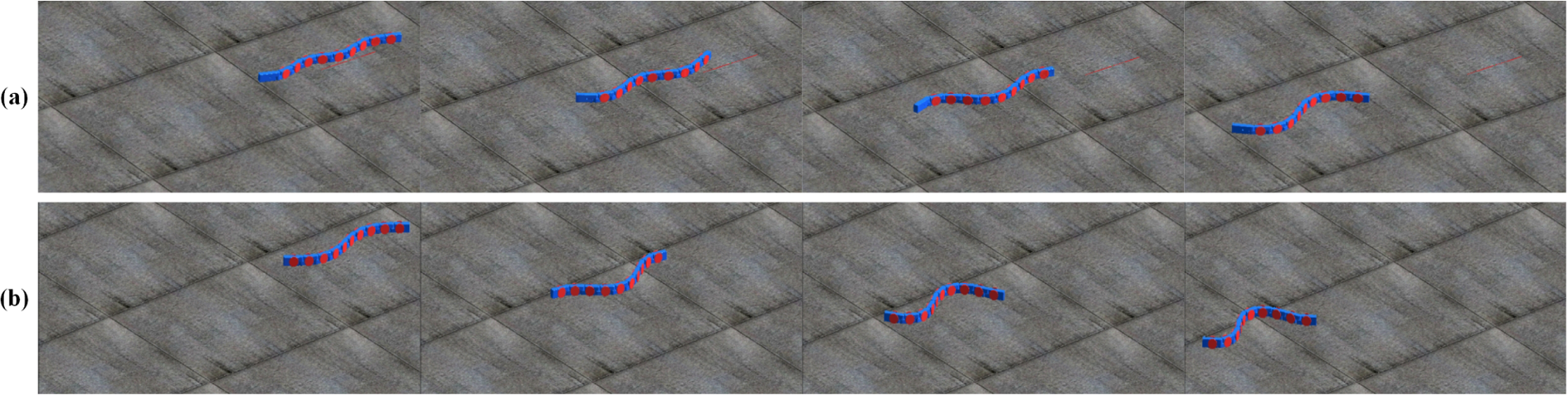
The initial state of the snake-like robot is shown in Figure 10(a). All joints of the snake-like robot were set at the equilibrium position. First, the simulations were performed to evaluate the locomotion performance of the snake-like robot with or without the proposed sigmoid start-up approach. As shown in Figure 13(a), the snake-like robot performed serpentine locomotion without sigmoid start-up approach. It can be found that the direction of the snake-like robot deflected with great deviation. The snake-like robot presented in Figure 13(b) was controlled by the proposed sigmoid start-up method. The direction of the snake-like robot is almost unchanged. Figure 14 depicts that the trajectory of the center of mass (COM) of the snake-like robot was recorded in the simulations. The direction deviation of the snake-like robot without sigmoid start-up approach is 4.5°. The direction deviation of the robot with sigmoid start-up approach is just 0.9°. Therefore, the proposed sigmoid start-up approach is evaluated to be effective.

The start-up of the snake-like robot. (a) The snake-like robot performed the serpentine locomotion without sigmoid start-up method. (b)The snake-like robot performed the serpentine locomotion with sigmoid start-up method.

The COM trajectory of the snake-like robot recorded in the simulation. (a) The snake-like robot without sigmoid start-up approach. (b) The snake-like robot with sigmoid start-up approach.
Second, the phase bias and amplitude of the CPG were, respectively, modulated in the simulations to evaluate the performance of the proposed sigmoid parametric modulation method. The snapshots of the two simulation processes were presented in Figure 15. As shown in Figure 15(a), the phase bias of the CPG were modulated at the time t = 4 s. The phase bias was changed from 4π/9 to 2π/9. Figure 15(b) presents that the amplitude of the CPG was also changed from π/6 to π/3 at the time t = 4 s.
The snake-like robot regulates its locomotion through modulating the parameters of the CPG. (a) The phase bias of the CPG is modulated from 4π/9 to 2π/9. (b) The amplitudes of the CPG are modulated from π/6 to π/3. CPG: central pattern generator.
During the simulations, the torques of the first joint motor of the snake-like robot were recorded. As shown in Figure 16(a), the snake-like robot performed the serpentine locomotion without the sigmoid start-up method. The torques of the first joint motor oscillated greatly before the snake-like robot performed the stable serpentine locomotion. The maximum torque of the first joint motor was 0.4182 N·m during the start-up process. In Figure 16(d), the torque of the first joint motor changed more smoothly when the snake-like robot performed locomotion with the proposed sigmoid start-up method. This can prevent the joint motors and the gearboxes of the snake-like robot from damaging. In addition, this method also reduces the energy consumption of the snake-like robot during the start-up process.

The comparison of the snake-like robot with/without sigmoid start-up and sigmoid transition methods. The torques of the first joint were recorded. (a) The snake-like robot performed the serpentine locomotion without the sigmoid start-up method. (b) and (c) The phase bias and amplitude of the CPG were modulated through step function. (d) The snake-like robot performed the serpentine locomotion with the sigmoid start-up method. (e) and (f) The phase bias and the amplitude of the CPG were both modulated through the sigmoid parametric modulation method. CPG: central pattern generator.
As shown in Figure 16(b) and (c), the torques of the first joint motor both changed abruptly when the phase bias and amplitude were, respectively, modulated by the SF-based transition method. This phenomenon is more obvious when the amplitude of the CPG is modulated. As shown in Figure 16(c), the maximum torque of the joint motor was about 1.453 N·m. It was nearly seven times that of normal values. However, the transition time is relatively short. Figure 16(e) and (f), respectively, presents that the phase bias and amplitude of the CPG are modulated through the proposed sigmoid parametric modulation approach. The transition period of the sigmoid parametric method is set as 2 s. It can be seen that the torques of the first joint motor both smoothly transited to the target curves. The simulation results demonstrate that the proposed two-layered CPG-based controller and the sigmoid parametric modulation method are effective.
Performance comparison with different methods
A comparison study has been done to evaluate the performance of the proposed sigmoid parametric transition method. Figure 17 shows that the phase bias is changed from 4π/9 to 2π/9 through the four different parametric transition functions. The transition periods of the four functions in which the modulated parameters transit from initial value to the desired value are set as equal. Both phase bias and the amplitude are modulated at the time t = 4 s in the simulations. In the simulation procedures, the torques of the first joint of the snake-like robot were recorded. The corresponding results are shown in Figure 18.

The comparison of the four transition functions with the same transition time.

The comparison of the snake-like robot with different parameter transition methods. The torques of the first joint were recorded. (a) and (e) The amplitude and the phase bias of the CPG were modulated by the first-order low-pass filter. (b) and (f) The amplitude and phase bias of the CPG were modulated by the second-order damped function. (c) and (g) The amplitude and phase bias of the CPG were modulated by a linear piecewise function. (d) and (h) The amplitude and phase bias of the CPG were modulated by the proposed sigmoid function. CPG: central pattern generator.
In Figure 18(a) to (d), the amplitude of the neurons in the CPG is modulated. When the amplitudes of the neurons are modulated through the first-order low-pass filter, the second-order damped function and the linear piecewise function-based transition methods, the torque of the joint motor all have abrupt changes with varying degrees at the transition time. As shown in Figure 18(a), the torque of the joint motor changes from 0.086 N·m to −0.011 N·m within 0.018 s when the first-order low-pass filter-based transition method is applied. Figure 18(b) shows that the torque of the joint motor changes from 0.086 N·m to −0.056 N·m when the second-order damped function-based transition method is applied. This will result in severe damage of the joint motors. The torque change in Figure 18(c) is relatively small when the linear piecewise function-based transition method is applied. Figure 18(d) shows that the proposed sigmoid parametric transition method can make the joint motor rotate smoothly.
Figure 18(e) to (h) shows that the phase biases of the neurons are modulated. The torques of the joint motors all do not have obviously abrupt changes. Only the first-order low-pass filter-based transition method is relatively unsmooth. When the sigmoid function and the linear piecewise function are applied, the transition processes are smoother but slower than the two foregoing methods. As shown in Figure 17, the two foregoing methods converge to the desired value faster than the two latter methods. Compared with the linear piecewise function-based method, the converge rate of the proposed sigmoid parametric transition method is slightly faster. The simulation results conform to the trends presented in Figure 17. Moreover, the results evaluate that the proposed sigmoid parametric transition method is effective.
Conclusion and future works
This article first presents a novel two-layered CPG-based controller for the planar snake-like robot. The snake-like robot can dynamically adjust its locomotion based on the sensory feedback. This can be implemented through modulating the control parameters of the CPG-based controller. The continuity criterion of the curves is applied to evaluate the continuity degree of the outputs of the CPG-based controller. In order to avoid the stiff and flexible impulses of the joint motors and the gearboxes, a sigmoid parametric modulation method and a sigmoid start-up method are proposed to eliminate or reduce the abrupt change of the outputs of the CPG-based controller. The sigmoid parametric modulation method makes the outputs of the CPG-based controller smooth and continuous. With the proposed sigmoid parametric modulation method, the continuity degree of the outputs of the CPG-based controller is C2. The locomotion of the snake-like robot has been simulated in the Webots. The simulation results show that the proposed two-layered CPG-based controller can easily control the snake-like robot. The movement transited smoothly when the parameters of the CPG-based controller were modulated. The snake-like robot could perform a stable and smooth start-up with the proposed sigmoid start-up method. In the start-up process, the energy consumption of the snake-like robot is reduced through the sigmoid start-up method.
Future work will focus on the transition period optimization, analysing the effect of physical features and applying the proposed methods to control a physical snake-like robot.
Footnotes
Declaration of conflicting interests
The author(s) declared no potential conflicts of interest with respect to the research, authorship, and/or publication of this article.
Funding
The author(s) disclosed receipt of the following financial support for the research, authorship, and/or publication of this article: This work was supported in part by Natural Science Foundation of China under grant 51675259, 51075198 and 61503180, the Jiangsu Province Universities Natural Science Research Program 16KJB460013, Scientific Research Funds of Nanjing Institute of Technology YKJ201611 and the Jiangsu Provincial Projects of 333 Talents Engineering.