
Abstract
Most recently, a miniature rotation robot has been proposed to allow imaging samples from multidirection for the first time. However, one existing problem for that rotation robot is that the alignment efficiency and accuracy is affected greatly by the alignment angle. This article investigates the effect of alignment angle on the alignment accuracy. Alignment accuracy is measured by sample’s position shift during a 360° rotation. Firstly, the miniature robotic system and its alignment principle are introduced briefly. Then, the source of alignment error is analyzed and the error model is built. After that, simulation results are given and indicate that as alignment angle increases, alignment error first decreases, then becomes stable and finally increases. Reasons for the trend of alignment error are explained. Finally, experiment results are demonstrated and have a good agreement with theoretical analysis and simulation results. The results indicate that 90° should be chosen as the alignment angle to ensure both alignment accuracy and alignment speed.
Keywords
Introduction
To observe and manipulate (Table 1) micro/nanometer-sized objects with an accuracy of micrometer and higher is important in many aspects, such as material characterization, cell manipulation, and microassembly in micro and nanoelectromechanical systems. 1 –4 In order to be able to characterize and manipulate tiny objects, those objects usually need to be seen clearly. Microscopic vision has been providing such visual data in various research studies.
List of variable.

However, most existing microscopic vision systems can only provide vision from one fixed direction, which causes some research less complete and less reliable. For example, an automatic cellular force microscope is designed to measure topography and stiffness of tube-like pollen cells. 5,6 Optical microscope and scanning electron microscope (SEM) have been used to observe defects on different kinds of magnetic glass-coated microwires. 7,8 However, one problem about optical microscope and SEM is that optical microscope and SEM can only provide vision for samples from one fixed direction. As a result, those research can only study properties on partial surfaces of samples, and other surfaces that are not visible on vision system are difficult to study. Nanostructures like nanospring, 9 nanofiber, 10 and nanowire 11 have also been observed and characterized with microscopic vision systems. Still, those systems can only provide vision from one direction and thus samples can only be observed and characterized on certain surfaces.
Some methods have been proposed to deal with existing microscopic system’s limitation of only being able to observe samples from one fixed direction. Rotating stages or cameras enables us to observe samples from multiple directions. 12,13 But the tilt angle of existing stages is usually below 90°, which renders some sample’s surfaces still invisible. Also samples are likely to move out of microscope’s field of view (FOV) during rotation. The second method is to install multiple microscopy cameras simultaneously, such as assembling an optical microscope, installing a miniature chargable-coupled device (CCD) camera on the lateral side of the SEM chamber, 14,15 and integrating three optical microscopes together. 16,17 Nevertheless, vision from other directions is still not available, and it is difficult to keep samples on good focus for all the microscopic cameras at high magnification. Another solution for multidirectional microscopic vision is to rotate the samples. To rotate the samples enables us to observe sample’s surface from different directions. However, it is difficult to manually realize the rotation if the sample is micrometer sized or smaller.
Robotic systems have been recently integrated with different microscopic systems to realize characterization and manipulation of material and biospecimens. 18 –22 However, few research studies have adopted robot systems to rotate samples and enable sample observation from multidirection. Most recently, a rotatable robot has been integrated with optical microscope and SEM to capture images for samples from multidirection. 23 The authors then adapt imaging processing technique to get a panorama image and dome projection result based on those captured images from various directions. Shen et al. 23 introduced the basic principal of the alignment, which is to align samples to robot’s rotation axis to prevent samples from moving out of microscope’s FOV. In the alignment, the sample is rotated forward and backward by an alignment angle. If the sample is not on the rotation axis, the sample’s position on the microscope image would change. Based on the position change, a strategy is introduced to calculate the relative distance between the sample and the rotation axis, and then the sample can be moved to the rotation axis based on the relative distance.
Although the alignment angle–based alignment has been realized in the study by Shen et al., 23 the reference doesn’t analyze factors that affect the alignment accuracy of the miniature rotatable robot. Thus, this work is proposed to examine the effect of alignment angle on alignment accuracy through both theory analysis and experiments. We first build an error model and give the trend of alignment error over alignment angle. Based on the built model, the reasons for the trend are illustrated theoretically. Then, the optimal alignment angle is deduced mathematically. To justify theory analysis, experiments to examine alignment accuracy are conducted when various alignment angles are adopted. Both simulation and experiment results show that initially when alignment angle is small, alignment error is large. Then, as alignment angle increases, alignment error decreases. When alignment angle is beyond 90°, alignment error becomes stable. After alignment angle continues to increase beyond a certain value (around 150°), alignment error would increase.
This article is organized as follows. “Principle of the alignment angle–based alignment” section gives a description about the principle of alignment, which is to locate the sample to the robot’s rotation axis. Theory analysis for alignment angel’s effect on alignment accuracy is illustrated in “Error analysis for the effect of alignment angle” section. The experiment results are shown in “Experiments and results” section. Lastly, we would make a conclusion to this article and discuss about other potential applications of the rotatable miniature robot.
Principle of the alignment angle–based alignment
The designed miniature rotation robot has two linear nanopositioners (LP_1 and LP_2) and one rotary nanopositioner (RP) and correspondingly three degrees of freedom (DOFs): two mutually perpendicular linear movements and one rotation movement. The nanopositioner’s movement mechanism is slip–stick mechanism. 24 The details of the rotation robot’s shape, structure, technical specifications, and other parameters can be found in the study by Shen et al. 23
The rotation robot would rotate so that samples can be observed from different directions. However, when samples are not on the rotation axis of the miniature robot, samples may move out of microscopes’ FOV. Therefore, a control strategy is designed to align samples to the rotation axis.
To illustrate the alignment principle mathematically, a moving coordinate {N} and a static coordinate {M} are built on the miniature robot and microscope’s image plane, respectively. As shown in Figure 1, the relative position between samples and rotation axis is calculated based on sample’s position shift on microscope images during miniature robot and sample’s rotation. Figure 2(a) is the schematic of the rotatable robot observed from ZN -axis. Po is sample’s initial position before rotation; Pf is sample’s position after rotating forward by an alignment angle α; and Pb is sample’s position after rotating backward by the same alignment angle α. Figure 2(b) is illustration of samples on microscope images. xo, xf, and xb are sample’s coordinates on microscope images before rotation, after forward rotation, and after backward rotation, respectively. The relative position between samples and rotation axis would be calculated based on those three coordinates. 23

Two coordinate systems. (a) The static coordinate {M} is established on the microscope’s image plane. (b) The moving coordinate {N} is established on the miniature robot.

Alignment principle. (a) The schematic of the rotatable robot observed from ZN -axis. Po , Pf , and Pb are sample’s positions before rotation, after rotating forward by an alignment angle α, and after rotating backward by the same alignment angle α, respectively. (b) xo , xf , and xb are sample’s coordinates on microscope images before rotation, after forward rotation, and after backward rotation by alignment angle α, respectively.
Suppose that a point on the sample has coordinate

where
After some derivation of formula, the details of which are given in the study by Shen et al., 23 sample’s coordinate in {N} can be calculated as

Equation (2) is exactly the relative coordinate of the sample to miniature robot’s ration axis, as the origin of {N} is set at the rotation axis. Since the miniature robot is unable to move in ZN
-axis, all points in samples have fixed ZN
coordinates. In equation (2), only point P’s XM
coordinates are used to compute the point P’s coordinate in {N}. After getting the sample’s coordinates from equation (2), the sample can be moved to the rotation axis of RP with LP_1 being moved by
As shown in equation (2), one advantage of this alignment angle–based alignment is that only through sample’s position information along one axis (both Δxf and Δxb are position information along XM -axis), sample’s depth information (yn0) can be calculated. This advantage can be explained by the fact that sample’s trajectory during miniature robot’s rotation is a circle, in which position information along XN -axis and YN -axis is related to each other.
Error analysis for the effect of alignment angle
Error modeling
As shown in equation (2), the alignment accuracy is dependent on alignment angle α and sample’s position shift (
All the errors would affect the calculation of

where

The alignment angle αm that makes e in equation (4) minimal can be calculated mathematically. Define

Because f(α) at αm is a minimal value, so f’(αm ) = 0. Then, the following equation can be achieved

Effect of alignment angle on error
To firstly qualitatively study the effect of alignment angle α on alignment error e, two different dimensionless values can be assigned to e1 and e2, respectively. First assume

Alignment error over alignment angle when
With different relationships between errors e1 and e2, alignment errors over alignment angle are also calculated and given in Figure 4. Totally, five relationships have been considered, that is,
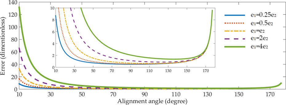
Alignment error over alignment angle for different relationships between two errors.
The reason why the alignment error is large for small alignment angle is that the denominator for calculating X-coordinate, 2 cosα − 2, in equation (2) is small when the alignment angle α is small. This small denominator functions as an “error amplifier” for calculator errors in the nominator,
As the alignment angle α increases, the absolute value of 2 cosα − 2 would increase, which means the error in nominator would be amplified less. Thus, alignment error would decrease, as shown in Figure 4. As the alignment angle continues to increase beyond a value, the denominator for calculating Y-coordinate, 2 sinα, would become smaller than the denominator for calculating X-coordinate, 2 cosα − 2. For instance, at alignment angle 165°, 2 sinα, 0.518, is more than seven times smaller than absolute value of 2 cosα − 2, 3.93. Therefore, alignment error mainly comes from Y-axis alignment error for large alignment angle.
Based on equation (6), the optimal alignment angle αm that makes alignment error e minimal over different error conditions is in the range of 90–150°. It should be noted that although there is only one optimal alignment angle, locating between 90° and 150°, there are not much difference in alignment accuracy when the alignment angle is between 90° and 150° (Figure 4) for different error relationships. In this range, alignment error keeps relatively stable at a minimal value.
Experiments and results
Experimental setup
Alignment experiments are given in this section to verify simulation results about the effect of alignment angle on alignment error. The experimental setup is shown in Figure 5. The goal of this control system is to make the to-be-aligned point on the sample has the same position on microscope images with initial microscope image during miniature robot’s rotation. This goal indicates that the to-be-aligned point of the sample is on the rotation axis.
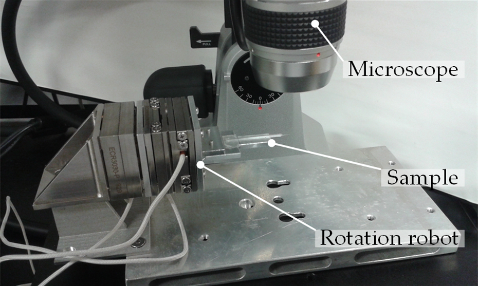
Experimental setup.
The alignment process is illustrated in Figure 6. First, we capture the first microscope image for the sample before RP’s rotation and calculate the to-be-aligned point P’s XM
-coordinate. Then, we rotate RP by an angle of α degrees clockwise, capture the second microscope image, and calculate point P’s XM
-coordinate in the second image. The third step is to rotate RP by an angle of 2α degrees in the opposite direction, capture the third microscope image, and calculate point P’s XM
-coordinate in this microscope image. After that, the differences between the three XM
-coordinates, that is, Δxf and Δxb, are computed. Then, sample’s coordinates

Process of alignment angle–based alignment.
Image processing to calculate sample’s coordinate is realized with OpenCV library, which has been integrated into the software of Microsoft Visual Studio [VERSION 2015] during experiments. The movement control of the miniature robot’s three nanopositioners is realized by the integration of Microsoft Visual Studio and the miniature robot’s dynamic-link library. The approach to calculate sample’s coordinate on microscope images is illustrated in Figure 7. The coordinate of sample’s rightmost tip would be calculated in Figure 7(a). The image in Figure 7(a) is first processed by Canny detection method with OpenCV, which can detect object’s edges. The processed result is shown in Figure 7(b), which is a binary image. Lastly, the coordinate of rightmost tip is calculated as


Calculation of sample’s coordinate by image processing. (a) Optical microscope images for a glass micropipette. (b) Image achieved by Canny edge detection method, which is a binary image.
The sample is a glass micropipette as shown in Figure 7(a). The micropipette’s tip is circular with a diameter of 10 µm. During image processing, we assume that the cross-section of the rightmost part of the glass micropipette is circular, and the center of that circle is going to be aligned to the rotation robot’s rotation axis. The optical microscope’s magnification is 30.
In order to examine the effect of alignment angle on alignment error, different alignment angles have been chosen to conduct alignment and the corresponding alignment results have been compared. According to the alignment theory and equation (2), the alignment angle is in the range of 0–180°, excluding 0° and 180°. Eleven alignment angles, 15n, (n = 1:11) have been chosen. Three experiments have been done for each alignment angle.
Alignment process
The alignment with alignment angle 90° is taken as an example to illustrate the process of the proposed alignment strategy. The process of alignment with other alignment angles is similar. With alignment angle 90°, the miniature robot is rotated firstly to 0°, then to 90°, and lastly to −90°. Correspondingly, three images before alignment at rotation angle −90°, 0°, and 90° are captured and shown in Figure 8(a). In Figure 8(a), because glass micropipette is not on the rotation axis, its position on the microscope images would experience large shift. The maximum position shift between the three images in Figure 8(a) is 1637.5 µm. Next, the control system calculates the position shift

Alignment results. The micropipette’s microscope images at rotation angles −90°, 0°, and 90° (a) before alignment and (b) after alignment with alignment angle 90°. The scale bar is 1 mm.
In order to ensure alignment accuracy, a second alignment with alignment angle 90° is conducted. Usually more alignments lead to higher alignment accuracy. Yet, many times of alignment are unnecessary and time-consuming, as later alignment would improve alignment accuracy little. In the second alignment, three images at rotation angles −90°, 0°, and 90° are captured. This time, the coordinate is
After that, the glass micropipette images were taken again at −90°, 0°, and 90°, which are shown in Figure 8(b). At this time, the maximum position shift between the three images in Figure 8(b) is 7.3 µm, much smaller than 1865.7 µm before alignment. The results of the alignment justify the feasibility of proposed alignment strategy to move samples to rotation axis.
In order to examine the quality of alignment, the miniature rotation robot is rotated and the sample’s position is calculated at different rotation angles. During experiments, the miniature robot is rotated from −180° to 180° and microscope images are captured during robot’s rotation. Then, sample’s position at those captured images is calculated. The further samples are away from rotation axis; the much sample’s position would change during rotation.
Figure 9 shows sample’s position at different rotation angle before alignment, after alignment with alignment angle 15°, and after alignment with alignment angle 150° for three experiments. Before alignment, the sample would experience a large position shift during rotation, which means the sample is far away from rotation center. After alignment, sample experiences smaller position shift during rotation, which means the sample has been moved to rotation center. Results in Figure 9 also indicate that the alignment accuracy is different with different alignment angles. When a small alignment angle is adopted, the alignment accuracy in the whole rotation range (−180° to 180°) cannot be assured, although the alignment accuracy can be assured in a small rotation range. For example, after alignment with 15°, the maximum position shift during rotation angle from −15° to 15° is 17.4 µm, whereas the maximum position shift during rotation angle from −180° to 180° has increased sharply to 614.0 µm.

Sample’s position with different alignment angles for three experiments.
Alignment error of different alignment angles
To evaluate alignment accuracy, define maximum shift (MS) and standard deviation (SD) of sample’s position as
MS represents the sample’s largest position shift during the sample’s 360° rotation, and SD is used to measure the dispersion of sample’s position during the 360° rotation. Smaller MS and SD mean the sample experience smaller position shift on microscope images and therefore better alignment.
Figure 10 and Table 2 give SD and MS for sample’s position during a 360° rotation after the sample is aligned to the rotation axis with different alignment angles. The best alignment accuracy is achieved with alignment angle 150°, with SD and MS being 19.3 and 89.5 µm, respectively. Initially, when the alignment angle is small, alignment error is large and mainly comes from X-axis alignment error,

Alignment error with different alignment angles.
Alignment error with different alignment angles.
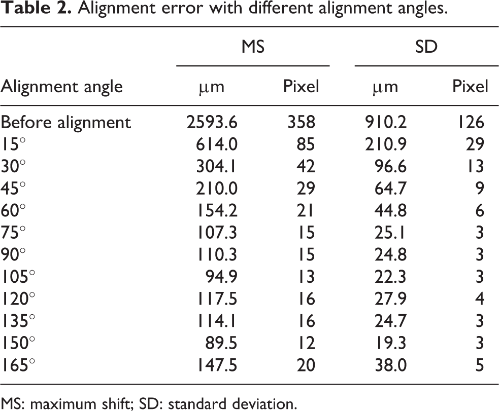
MS: maximum shift; SD: standard deviation.
Also, the trend of alignment error over alignment angle in experiment results of Figure 10 is in agreement with simulation results of Figure 4. However, one difference between experiment results and simulation results is that there are fluctuations in the range between 90° and 150° in experiment results, while there are no such fluctuations in simulation results. The deviation between experiment results and simulation results is caused by systematic errors and environmental disturbance. When alignment angle α is small, alignment error is large. In this case, relatively small systematic errors and environmental disturbance are ignorable. However, as alignment angle α increases, alignment error becomes small, and under this condition, uncertain systematic errors and environmental disturbance would comprise a large part of alignment error. Therefore, when alignment error is small, variations of systematic errors and environmental disturbance would lead to fluctuations of alignment errors.
It should be pointed out that in experiments, the magnification of only 30 is adopted. Such a low magnification is chosen to prevent samples from moving out of microscope’s FOV, especially when a large alignment angle is adopted. When the sample is not on the rotation axis, larger alignment angle leads to larger shift of sample position on microscope images. Therefore, a low magnification and thus a large FOV are chosen to avoid sample’s moving out of microscope’s FOV. In real practice, a large magnification should be adopted to achieve higher alignment accuracy, as a larger magnification results in smaller imaging processing errors. Under this condition, before alignment with large magnification, alignment with small magnification should be conducted first to roughly align the samples to rotation axis, so that during sample’s rotation with high magnification, samples wouldn’t move out of microscope’s FOV. In this article, because we aim to study the effect of alignment angle on alignment accuracy, other factors are kept the same, except the alignment angle. Therefore, a low magnification of 30 is applied for all the alignment angles.
As for potential solutions to reduce alignment error, environmental disturbance and image processing errors can be decreased by careful experimental setup and adopting microscopes with high magnification microscopes. Mechanical assembly error, nanopositioner’s positioning error, and the whole robot’s orientation error can be reduced by a real-time control approach that would move the two linear positioners during rotary positioner’s rotation to adjust the sample’s location so that samples can be always kept at the desired location. In this article, after alignment, the two linear positioners wouldn’t move when rotary positioner is rotating.
Discussion
Microscopic systems have proven to be important tools for providing visual data in micro/nano field. Nevertheless, researchers can only observe certain surfaces of samples with most existing microscopic systems, and many other surfaces are not available. Previously, a rotatable miniature robot has been proposed to provide sample’s observation from multidirection.
The proposed miniature robot has three nanopositioners, every one being responsible for one degree of freedom, and therefore, the miniature robot has three degrees of freedom: one rotary movement and two mutually perpendicular linear movements. The rotary movement is aimed to rotate samples and therefore realize multidirectional observation. The two linear movements are to move samples to rotation axis of RP. The three nanopositioner’s movement mechanism is slip–stick technique. One advantage of our design is that more nanopositioners can be added easily to increase DOFs. In this case, coupling control can be adopted to increase control accuracy. The nanopositioner’s resolution is 1 nm, and this high resolution is high enough to fulfill the requirements of microscopic imaging in micro/nano field.
When samples are not on the miniature robot’s rotation axis, samples’ positions on microscope images would change. A larger distance between samples and rotation axis leads to larger position shift. Correspondingly, samples may move out of microscopes’ FOV, especially when the magnification is large. Therefore, an alignment angle–based alignment strategy to align samples to rotation axis has also been proposed in the previous article. In this alignment angle–based alignment strategy, samples are rotated forward and backward by the same alignment angle. During this forward and backward rotation, samples would experience position shift on microscope images. According to the position shift, the relative distance between samples and rotation axis can be calculated and then samples can be moved to rotation axis by miniature robot’s two linear movements.
Because of existence of errors, there would be alignment error. Alignment errors come from mechanical assembly of the miniature robot’s three positioners, position errors of the miniature robot’s three positioners, position adjustment of the miniature robot before experiments, image processing errors, system errors, and environmental disturbance. Because all these errors would affect the calculation of sample’s positions on microscope images, we build an error model that attributes errors to sample’s positions. Based on the model, the trends of alignment error over alignment angle for different error conditions are first given through simulation and then explained mathematically.
Simulation results and experiment results show that alignment error is affected largely by alignment angle. According to proposed alignment principle and equation (2), the alignment angle is between 0° and 180°, excluding 0° and 180°. When alignment angle is small, for example, 10°, the alignment angle is large and mainly comes from X-axis alignment error. This is because for a small alignment angle, the denominator for calculating X-coordinate is small and acts as an error amplifier. As alignment angle increases, the X-coordinate’s denominator increases and the effect of error amplifier decreases. As a result, alignment error would decrease. When alignment angle is between 90° and 150°, alignment error keeps stable at a small value, as a result of increasing X-coordinate’s denominator and decreasing Y-coordinate’s denominator. As alignment angle continues to increase beyond 150°, alignment error would increase and mainly comes from Y-axis alignment error. This is because for a large alignment angle, the denominator for calculating Y-coordinate is small and would amplify errors in numerators.
Overall, experiment results and simulation results agree well. One difference is that alignment error experiences small fluctuations for experiment results when alignment angle is between 90° and 150°, whereas alignment error keeps smooth for simulation results in the range of 90–150°. The reason is that when alignment angle is between 90° and 150°, alignment error is at its smallest value. Under this condition, systematic errors and environmental disturbances cannot be ignored, and uncertain systematic errors and environmental disturbances would make alignment error fluctuate. When alignment angle is in other ranges, alignment error is relatively large and systematic errors and environmental disturbance are too small to cause any fluctuation in alignment error.
Usually, there will be an optimal alignment angle, locating between 90° and 150°, which makes alignment error minimum. Yet, according to our experiment and simulation results, there are not much difference in alignment error when alignment angle is between 90° and 150°. For example, when alignment angle is between 90° and 150°, the SD and maximum difference of SD are 3.2 and 8.6 μm, respectively (Table 1). Therefore, it is recommended that 90° should be chosen as the alignment angle to realize a fast automatic alignment, as a small alignment angle can reduce rotation time during the process of calculating the relative distance between samples and rotation axis. Although this article’s main work, error modeling and error analysis, may seem a little simple from the view of robot control theory, this simple method realizes optimization of the alignment accuracy for the first time. In the future, the alignment accuracy can be further improved by real-time control. Namely, the two LPs would also be actuated during RP’s movements.
Conclusion
Most recently, a miniature rotation robot for multidirectional microscopic vision is designed and an alignment angle–based alignment strategy is proposed to align samples to rotation axis to prevent samples from moving out of microscope’s FOV. In this alignment strategy, the robot is rotated clockwise and anticlockwise by the same alignment angle to calculate samples’ position relative to rotation axis. This article is proposed to study the effect of alignment angle on alignment accuracy, which has not been investigated previously. Alignment error is caused by errors such as mechanical assembly errors and positioner errors of miniature robot’s nanopositioner. An error model is built to analyze alignment angle’s effect mathematically, and then experiments are conducted to calculate alignment error for different alignment angles. Both simulation results and experiment results show that alignment errors are dependent on alignment angle. Initially, alignment error would decrease as alignment angle increases. Then, alignment error would keep stable before experiencing an increase. One possible solution to reduce alignment error largely is to adopt a real-time coupling control approach that would move the two linear positioners during rotary positioner’s rotation. As for applications, the miniature robot can be used to measure stiffness of tube-like pollen cells on different surfaces, not just on part of surfaces. It can also be used to observe defects on wire/rod-like micromaterial from different directions, compared with just one direction. Besides, as the miniature robot is able to rotate, it can be applied to measure rotational properties, such as rotational stiffness and torsional constant.
Footnotes
Declaration of conflicting interests
The author(s) declared the following potential conflicts of interest with respect to the research, authorship, and/or publication of this article: Wenfeng Wan and Haojian Lu contribute equally to this paper.
Funding
The author(s) disclosed receipt of the following financial support for the research, authorship and/or publication of this article: The authors thank the funding supports by the National Natural Science Foundation of China (61403323), ShenZhen (China) Basic Research Project (JCYJ20160329150236426), and Research Grants Council of Hong Kong (CityU 11278716).