
Abstract
Modern pipelines are often very long, having bends, branches and even variable diameters. Moving inside such pipelines to perform certain tasks has not been easy. There are various design concepts for traction inside a pipe. Screw drive is one of the concepts for in-pipe traction. This article presents a general description and analysis of available screw drives that have been used for in-pipe drives. The main focus is on the characteristic analysis of a novel variable radius screw drive mechanism that is proposed by the authors. The proposed mechanism is a two-stage planetary gearing system driven by a single motor. Major parameters of the mechanism, including helical angle, pitch and forward velocity, are derived. Furthermore, by conducting a force analysis, it is found that the proposed mechanism has much larger thrust force compared with that of the existing screw drive mechanism. A larger thrust force means that the proposed mechanism can carry more devices, thus perform more tasks inside pipes. To demonstrate the effectiveness of the proposed mechanism, thrust force measurement experiments have been conducted.
Introduction
Pipelines are pervasive in our everyday life. They are inside our kitchens and bath rooms. They also play an indispensable role in transporting gas, liquid and other chemical materials, both in urban areas and in the fields. Problems caused by pipelines, as trivial as a bath room pipe clogging, or as serious as a gas/oil pipeline explosion, are not uncommon. From 1994 through 2013, the United States had 855 serious incidents with gas transmission and distribution in pipes, resulting in 319 fatalities and 1254 injuries, with USD $559,558,416 in property damage. 1 Pipeline problems are often a direct result of neglected maintenance. It is unavoidable that pipelines might get corroded by chemical elements or damaged by external factors over time. Inspection and rehabilitation of these pipelines usually take huge amount of work and cost a lot of money, because pipelines often have very poor accessibility. To solve this problem, various mobile in-pipe robots have been developed. 2 Most of these in-pipe robots are used to detect inner surface problems. Some heavy load in-pipe robots can also carry tools with them and perform repair or maintenance tasks. 3
These mobile robots or mechanisms can normally be classified into seven types based on their locomotion methods, including pig type, 4 wheeled type, 5 –7 caterpillar type, 8 walking type, 9 inchworm type, 10,11 screw type 12,13 and snake type. 14 Each type of the design has some advantages over others in some aspects. The actual design adopted might depend on the task space of the required applications. Among them, screw type is a good choice when the pipe’s diameter is small. This is because that the screw mechanism is simple and compact. It can easily be designed to work with only one actuator, thus reducing the weight of the screw drive and simplifying the motion control.
This article is organized as follows, after a review of literature in second section 2, the novel variable radius screw drive mechanism is proposed in the third section. The fourth section presents the new screw drive mechanism analysis of the screw angle, helical pitch and forward velocity. Experimental studies are shown in fifth section. Discussions and conclusions are drawn in sixth and seventh sections.
Review of literature
Some research or investigations on mobile robots using screw drive mechanism have been done so far. Iwashina et al. 15 first came up with an in-pipe moving mechanism based on the principle of screw. The robot is made up of several units and they are connected by coil springs. Each unit has their twisted arms located at every 120° and at the end of each arm mounted a rubber wheel. The maximum moving speed of the mechanism can achieve 100 mm/s while its maximum traction load is 9.5 N. Following this design, Hayashi et al. 16 made some improvement to the mechanism, adding a small wheel preloading unit that helps to keep the robot stable when moving in pipe. The experimental result showed that the robot can easily pass through a small bent pipe having inner diameter of 27 mm and radius curvature of 200 mm.
Wu et al. 17 proposed a micro in-pipe robot with screw motion moving mechanism and a CCD camera that can send back real-time images inside the pipe. Its screw motion mechanism uses tilted wheels that rotate about the axis of pipe to drive the whole body. Thus, the tilted wheels move along screw trajectory. In their study, the kinematic model of this mechanism is derived and driving torque is calculated. Kakogawa and Ma 18 uses similar screw drive structure in in-pipe robot, and Lee et al. 19 presented novel mechanisms of screw drive in-pipe robot. But these two studies focus more on their mobility inside curved or branched pipes. Calculation and testing of tractive force performance are not mentioned.
Apart from these screw drive mechanism with simple structures listed above, there are also more complicated mobile robots that move in screw locomotion. Hara et al. 20 and Fukushima et al. 21 have developed a snake-like robot using screw drive mechanism. The robot is made up of several screw drive units and has omnidirectional mobility due to its multiple angled wheels in each unit. Since each screw drive unit of the robot is equipped with a motor, the control design of the whole system is quite complex. In order to provide better mobility, Liu et al. 22 have cascaded three screw drive robots and programmed them to inchworm motion.
From literature review, we can see that although screw drive mechanisms have been used in in-pipe robot, some problems still existed and there is a room for improvement. Existing structures of simple screw drive mechanism can only provide small propulsion, which is a limitation of its use in in-pipe robots or mobile robots. While some robots using screw drive mechanism can provide larger propulsion with more complex structure and more actuators, which adds huge work to designing their control system. Or a reduction gear box is used, which adds the whole mechanism’s weight. Therefore, it is of high importance to design a screw drive mechanism with simple structure and one actuator but can provide larger propulsion. Besides, pipeline’s diameter will vary in practice use because of many reasons. Thus, it is quite necessary for the screw drive mechanism to have variable radius function so that in-pipe robots equipped with it can adapt to pipes with different diameters.
This article presents a novel variable radius screw drive mechanism that can be applied to in-pipe robots. The concept of this new mechanism is given and it is compared with a traditional variable radius screw drive mechanism which uses compressed springs to pass through pipes of different diameters. Advantages of this innovated mechanism are shown by the comparison.
The novel variable radius screw drive mechanism design
Inspiration of the pipe unclogging snake
Plumbers fix clogged pipes using a very simple tool named ‘snake’ as shown in Figure 1(a). The snake can be as long as 10 m or more. Even though very simple, the snake can fit into pipes with a large range of diameters as shown in Figure 1(b). When the snake wiggles into a pipe, it forms helical coils against the pipe as shown in Figure 2. When the plumber keeps rotating the hand H, the snake will be pushed forwards and forms more helical coils inside the pipe. The following is just a simple explanation of why the snake can move deep inside a pipe.

Snake fit into pipes: (a) snake and (b) inside a pipe.

Illustrative diagram showing the snake inside a pipe.
When the snake is rotated at the handle H as in Figure 2, the snake becomes longer and exerts a force at the first contact point C between the snake and the pipe. The spring force F at the first contact point C can be resolved into an axial force Fa
and a normal force N. The spring force at point C is
When
Variable radius screw drive mechanism design
Inspired by the pipe unclogging snake, a novel mechanism driven by only one motor is proposed. Spring presses wheels firmly against the pipe wall so as to generate an axial force Fa and a normal force N, which are similar to Figure 2. Function of variable radius makes the mechanism adapt to the pipe diameter changes. Two planetary gear transmission is used instead of the pure frictional transmission to get higher transmission efficiency and more accurate trajectory. Compared to the pipe unclogging snake, this novel variable radius screw drive mechanism allows the robot go ahead, without the overall length limitation.
Figure 3(a) shows the overall system design concept. The system has four major parts. The first is the motor that provides the power for driving the robot. The second is the stabilizer that keeps the whole system stable when it is moving. The third one is the planetary gear set 1 that has three planet gears and transmit power to the planetary gear set 2. The last one is the planetary gear set 2 (three gears with modified teeth) that provides the driving force for the system to move along the axis direction of the pipe. Both the stabilizer and the planetary gear set 2 have a spring force to keep the wheels or gears in firm contact with the pipe. In order to provide a driving force, the gears (can be treated as wheels) on the second planetary gear set are tilted an angle as shown in Figure 3(a) and (b) so that when the wheels rotate, they rotate in a helical path. The helical motion of the three gears provides a driving force along the axis of the pipe. The driving force is ensured by the mechanism that can keep the gears in firm contact with the pipe as in Figure 3(c).
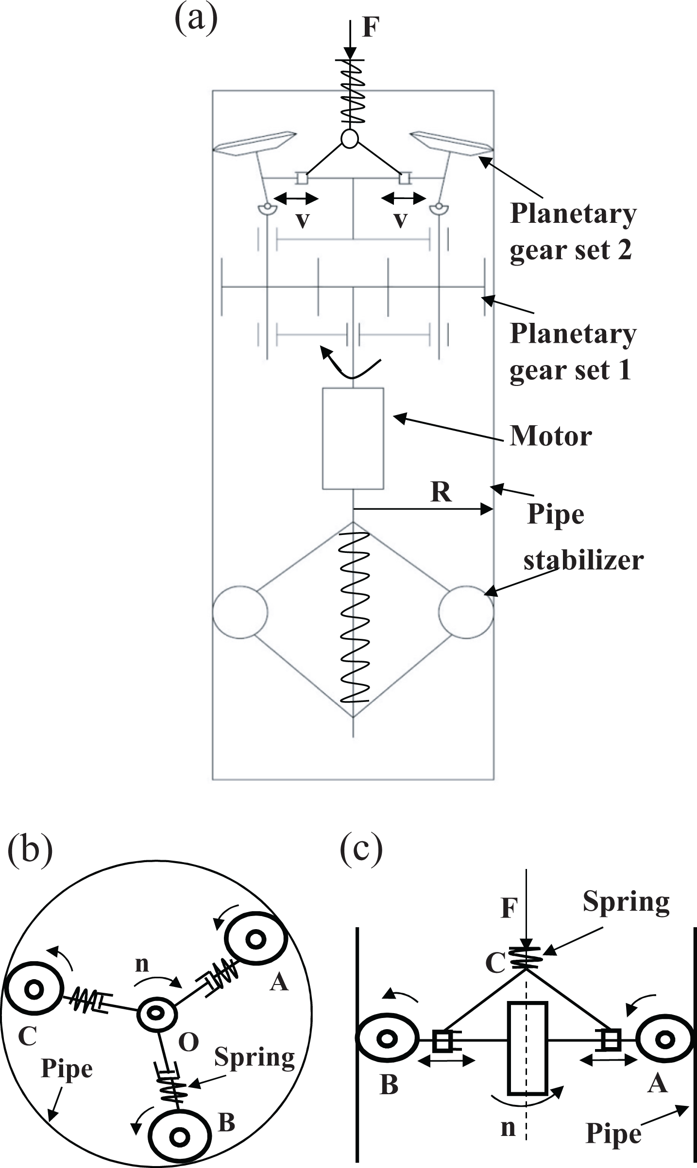
The design concept: (a) the overall concept diagram, (b) driving mechanism diagram and (c) contact force control mechanism.
Since the whole robotic system is driven by the helical motion of the planetary gear set 2 (hereafter they are called the driving gears), the following will mainly focus on discussing the basic principle of the driving gears. Figure 4 shows the three-dimensional drawing of the driving gear set design. All of the three gears can be inclined along their respective axis as shown in Figure 4(a) and (b). The larger the pipe diameter, the more the gears will incline outward.
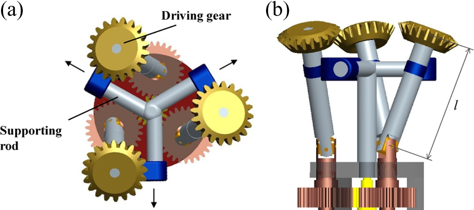
Structure of novel variable radius screw drive robot: (a) front view and (b) side view.
In Figure 5(a), the three inner circles represent the three gears at their initial position. When they are used for a pipe tracking as indicated by the largest circle in Figure 5(a), the three gears must be inclined to have firm contact with the pipe. The inclination angle of the three gears is shown in Figure 5(b). In Figure 5(a), the radius of the pipe is R, the radius of the driving gear is r, the distance between the axis of the pipe and the axis of a driving gear when it is at its initial position is d, the distance between the axis of the supporting rod and the axis of a driving gear when it is at its original position is d 0. In Figure 5(b), we can see that the axis of a driving gear is along the pipe centre line at the initial position. After inclination outward for an angle θ, the driving gears look elliptic along the pipe axis.

Geometric parameters of the in-pipe robot: (a) original driving gears’ position and inclined position and (b) definition of driving gear’s inclination angle.
The new screw drive mechanism analysis
In the following analysis, we assume that the axis of the pipe is vertical while a plane that is perpendicular to this axis is a horizontal plane. The robot is moving along the pipe.
In Figure 6, a driving gear’s position and its trajectory are shown. At the moment, the contact point of the driving gear on the pipe wall is R. When the robot is moving in the pipe, the driving gear’s trajectory on the pipe is helical, as is indicated in Figure 6. To calculate the screw angle, it needs to be defined first.

Screw trajectory of the driving gear.
In Figure 7, at the contact point, the driving gear’s plane intersects with the pipe and produces an elliptic curve on the pipe wall. The plane also intersects with the pipe’s axis at the intersection point P. The driving gear’s plane is called e. The lowest point of the elliptic curve on the pipe wall is M. Through M, a plane is built perpendicular to the pipe axis. We call this plane f. Plane f intersects with the pipe axis and the intersection point is Q. Plane e and plane f intersect with each other and M is on the intersecting line. A is another point on the intersecting line and thus MA stands for this intersecting line. We can see that MA is a tangent line of the elliptic curve. Therefore,

The angle between two planes.
Since the inclination angle of the driving gear from its original position is θ, it is obvious that the driving gear’s plane has an inclination angle θ from the horizontal plane. Because plane f is also horizontal, the angle between plane e and plane f is θ. Therefore,
In Figure 8, through point R, we draw a tangent plane of the pipe wall, which is called plane g. Plane g intersects with line MA at point T. From point R, a line is drawn perpendicular to plane f, the intersection point of the perpendicular line and plane f is S. It is obvious that RS is the intersection line of plane g and the pipe. RT is a tangent line of the ellipse which is on the pipe. RT is also tangent to the driving gear’s outline.

Tangent plane of the pipe: (a) location of the tangent plane and (b) projection on bottom plane.
We define

The screw angle of driving mechanism.
To calculate ∠RTS, line RN is drawn perpendicular to line MT in plane e, as shown in Figure 10. In plane f, we name the angle ∠SQM as β. From geometrical analysis, the following relations can be obtained


Calculation of the screw angle: (a) the screw angle of driving mechanism and (b) bottom plane.
In ΔRST

Here we take β as a constant. Therefore, the screw angle is

We can see from equation (6) that if β = 0°, then λ = 0°, and if β = 90°, then λ = θ.
On plane f, the base coordinate is established as x–y coordinate, the origin is Q, y axis is along the axis of supporting rod and x axis is perpendicular to y axis and makes the outline of driving gear in the first quadrant as shown in Figure 11. The circular curve of the pipe’s outline in x–y coordinate is expressed as

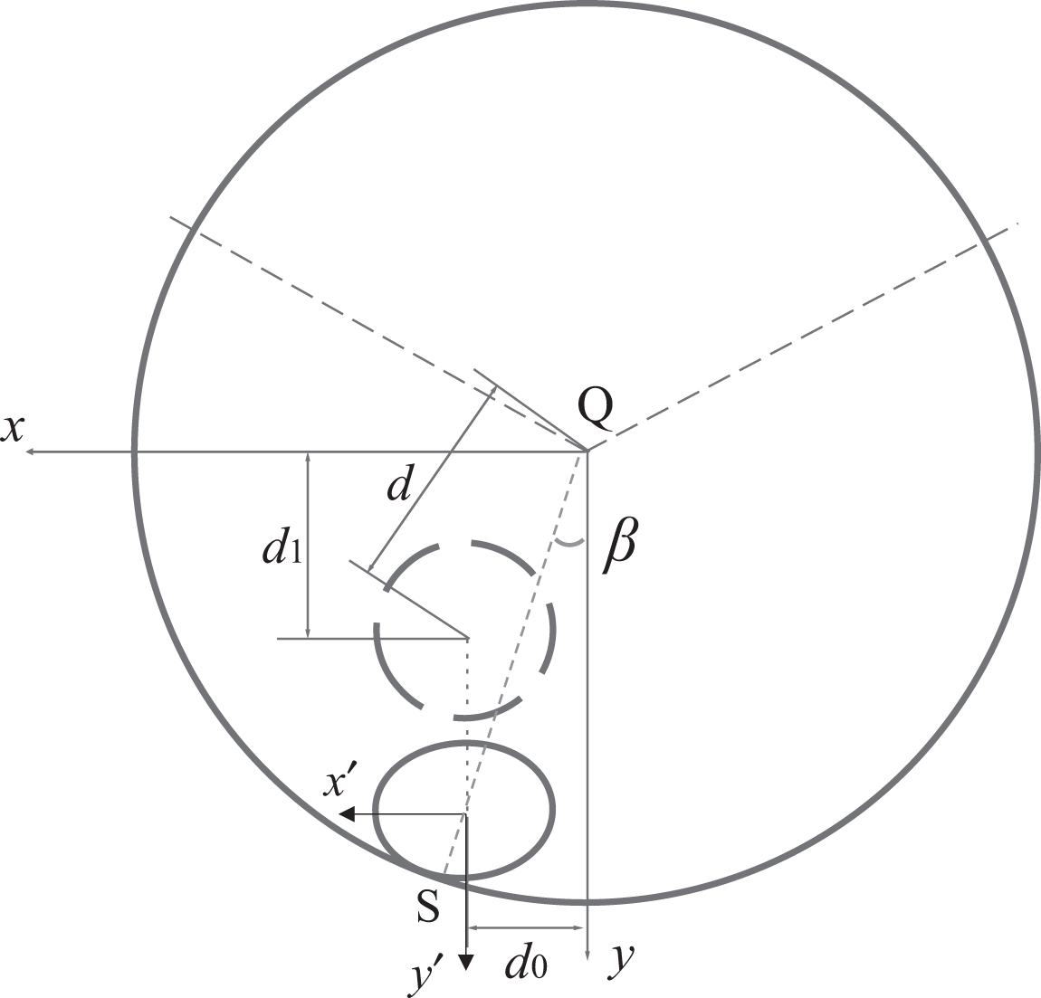
Coordinate transformation.
While the outline of a driving gear’s projection on plane f is an elliptic curve, we establish x′–y′ coordinate with the origin located in the ellipse’s centre and x′ and y′ both in same direction as x axis and y axis. Then, the expression of driving gear’s projection in x′–y′ coordinate is

The coordinate transformation from x′–y′ to x–y is
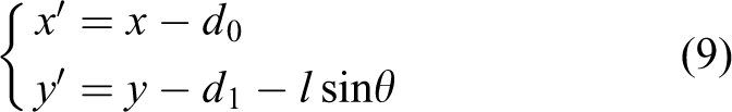
where

The geometric meaning of d 1 is shown in Figure 11.
It is shown in Figure 11 that the transformation includes only translation. Substituting equation (8) with equation (9), another equation about x and y is obtained. Equations (7) and (8) have made up a binary quadratic equation set regarding to x and y.
Because that the circular curve is internally tangent to the elliptic curve, the equation set to solve (x, y) should have only one efficient solution. To guarantee it, we can build the relationship between R, r, l, d, d 0 and θ. Angle θ can be expressed using these five parameters

Under the condition that R, r, l, d and d 0 are all known, θ can also be calculated. By solving equations (7) and (8) with only one set of efficient solution, the relationship between θ and R, r, l, d and d 0 can be obtained

where


Solving the equations (7) and (8), we get the solution

So β is obtained. Substituting θ and β in equation (6), the screw angle λ is obtained.
Once a design is given, the mechanism’s dimensions are fixed and therefore r, l, d and d 0 all have fixed values. R is a variable since the radius of a pipe may change according to applications. When the value of R varies, the values of θ and λ also vary accordingly. Although in equation (11) we have built the relationship between R and θ, it is not very intuitive due to the complex equation. Hence, we will draw two graphs of R–θ and R–λ.
Assuming that r, l, d and d 0 are all given as 20, 80, 25 and 20 mm, when R varies from 50 mm to 75 mm, two graphs are obtained as shown in Figures 12 and 13. We can see that as R increases, both θ and λ increase accordingly. However, the increasing speed of λ is slowing down with the increase of R.

R–θ relationship.

R–λ relationship.
We know the trajectory of the driving gears on the pipe is helical. Pitch of the helical path, p, is the axial translation when the rotation of the screw is φ = 2π. Since we have got screw angle λ, we have

where

The forward moving velocity of the robot along the pipe is vf, while the velocity of a driving gear’s contact point with the pipe is vg. Because of the helical trajectory of driving gears, vf and vg have the following relationship

Besides, each gear rotates with an angular velocity ω g, therefore v g is

Experiments
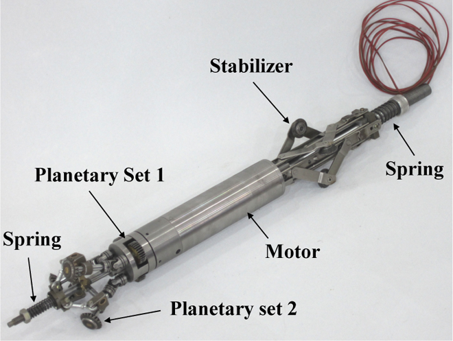
Based on the concept, a prototype variable radius screw drive in-pipe robot is developed as shown in Figure 14. We can clearly see that this mechanism has four parts: (1) planetary gearing set 1: the first set transfer motion from the motor to the second set; (2) the second gear set has three driving gears that move in helical trajectory along the pipe wall; (3) motor: the actuating device (Maxon motor, diameter 36 mm, length 60 mm, voltage 24 V, power 60 W, unload speed 170 rpm); (4) stabilizer: it is made up of three guide wheels to guarantee that the motor and stabilizer only moves along the axis of the pipe with no rotation.
The prototype.
In order to compare the performance of the presented in-pipe helical tracking robot with that of the previous helical robots, experiments on tracking forces are measured. A sample popular previous helical drive in-pipe robot design shown in Figure 15 is used here for comparison. 23 Figure 15(a) is the diagram showing the previous helical drive robot. It has one motor that drives the links of three wheels. The wheels are tilted an angle so that they can move in a helical path when they rotate. A prototype of the in-pipe robot is shown in Figure 15(b).

A popular helical drive in-pipe robot: (a) a popular helical in-pipe robot design and (b) prototype of the in-pipe robot.
The experiments for driving force test are conducted as shown in Figure 16(a). Figure 16(b) shows a snapshot of the test process. It is found that the design in Figure 15 can only carry a maximum load of up 16 N while the one presented in this research can carry a maximum load up to 500 N. From the experimental results, it can be seen that the one shown in this research can carry a much larger load (over 30 times) than the previously popular helical drive design.

The experimental set-up: (a) diagram of the set-up and (b) test of in-pipe robot load carrying capability.
Discussions
When turning a bend, the robot can be approximated by its minimum enclosing cylinder with a length L and diameter d. In turning around an L-bend with a diameter D and radius R, the critical position of a robot is shown in Figure 17.
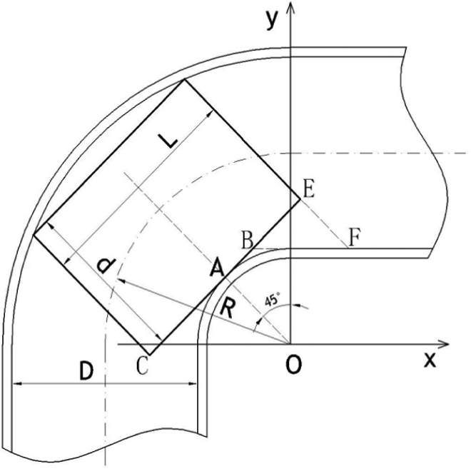
Critical position when turning an L-bend.
From Figure 17, an equation can be obtained as follows 24

At the above critical position, the turning will fail if any of the following is true: the length of the robot is larger than L, or the robot’s minimum enclosing cylinder’s diameter is larger than d, or the pipe’s diameter is smaller than D, or the bend’s radius is smaller than R.
When the dimensions of the current prototype are known, d = 75–100 mm and L = 730 mm, it can go through bends with the radius R larger than 2.627 m. Thus, the long driving motor makes the device hard to go through small pipe bends. However, this design can be used to convey downhole tools and apparatus for well logging, workover and perforating in deep and long horizontal oil or gas wells. 25
Conclusions
In this article, analysis of a new variable radius helical drive mechanism has been presented. Unlike the most existing screw drive mechanisms reported previously, this new designed mechanism adopts two sets of planetary gears to drive the mechanism (one set for power transmission and the other set for providing traction). Each driving gear rotates about its axis actively similar to the planet gear of a planetary gear system. Different parameters of the new mechanism are deduced including screw angle, pitch and forward or backward moving velocity. By comparison using experiments, we find that this new variable radius screw drive mechanism can provide much larger traction force than the existing helical drive mechanism under condition that the two mechanisms have the same dimension and same motor output.
However, each driving wheel is connected by a universal joint that is rotating at an irregular speed, which may induce motion interference of the three driving wheels. But it has little effect on the rotation speed in the case of small radius driving wheel. In-pipe robot with the ability of passing through small bends usually lose the ability of large tractive force, which will help carry more tools to accomplish inspection and rehabilitation jobs in pipes. The current design of the driving mechanisms and the use of long motor result in an in-pipe robot with large tractive force in this article. However, the present design and geometry lose the ability of going through small pipe bends. In recent years, the authors did some research on the variable pitch helical drive mechanism to pass through curved pipes better. 26
Future work will focus on adding pressure sensors to the driving wheels so that to make the proposed robot be adaptive to pipe diameter or shape changes as well as solving the problem of motion interference. In addition, the performance of going through small pipe bends without losing large tractive force will be improved in the future work.
Footnotes
Acknowledgements
The authors acknowledge Sichuan Province of China Science and Technology Support Program for their support in this research.
Declaration of conflicting interests
The author(s) declared no potential conflicts of interest with respect to the research, authorship, and/or publication of this article.
Funding
The author(s) disclosed receipt of the following financial support for the research, authorship, and/or publication of this article: This work was supported by Sichuan Province of China Science and Technology Support Program (project code: 2016GZ0190). Research project of key laboratory machninery and power machinery (Xihua University), Ministry of Education, China.