
Abstract
In this paper, we propose a robust and real-time localization method for dynamic environments based on a sensor network; the method combines landmark image information obtained from an ordinary camera and distance information obtained from sensor nodes in an indoor environment. The sensor network provides an effective method for a mobile robot to adapt to changes and guides it across a geographical network area. To enhance the performance, we used a charge-coupled device (CCD) camera and artificial landmarks for self-localization. Experimental results showed that global localization can be achieved with high robustness and accuracy using the proposed localization method.
Introduction
One of the most important goals in the mobile robotics field is to give robots the ability to fulfill user-specified tasks in an indoor structured environment. To do this, a general localization awareness method for mobile robots in an indoor environment is essential to navigate the robot. This has been implemented by various applications of radio-frequency (RF) signals in wireless environments. There have been numerous approaches to the localization problem, such as using a received signal strength indicator (RSSI) and time-difference-of-arrival (TDOA) estimation, time-of-arrival (TOA) estimation, and angle-of-arrival (AOA). These methods generally rely on trilateration or triangulation techniques to calculate positions using distances and angles between the receivers and transmitters. However, these RF-wave–based localization methods have serious problems. The inherent characteristics of RF waves make it difficult to resolve problems such as multi-paths, collisions, interference, and line-of-sight, which can deteriorate and destabilize signal delivery. Various studies have attempted to overcome these problems, but the characteristic problems of waves still remain. Representative studies include Active Bat, RADAR, DOLPHIN, Cricket system, and other applications [1–5].
Another important localization method in real-time environments is vision-based localization, which uses image processing and computer vision. Vision-based localization generally uses two types of landmarks to extract specific target images from background images: natural and artificial. The natural landmark method considers geometrical or photometrical features from original image data and then distinguishes distinctive target images from the background. The mobile robot extracts natural landmarks using those natural features and performs localization to calculate its current position. However, this method is very sensitive to dynamic environments, and image processing is very time-consuming; thus, extracting and using natural landmarks for reliable real-time localization is difficult [6]. To compensate for the disadvantages of the natural landmark method, artificial landmarks are generally used for vision-based localization. The artificial landmark–based approach has small computational overhead for image processing and makes it easier to extract landmarks from the original image data. However, it is disadvantageous that many artificial landmarks must be installed.
Indoor robot localization is a very old issue, but it still requires an innovative idea to provide a practical solution to real service robot applications. Though recent researches on simultaneous localization and mapping (SLAM)[7–13] have achieved good localization performance in laboratory, we think there remain many challenging problems for real environmental application. Therefore, we tried to develop a practical solution for indoor mobile robot navigation. Basically, this work focused on an accurate absolute-localization method for indoor autonomous navigation of a mobile robot for ubiquitous home security service. We propose an enhanced localization method to compensate for disadvantages of the conventional localization methods: the method combines the TDOA distance information obtained from each sensor node of a sensor network and artificial landmarks from the vision system.
System configuration
In a previous study [14], we proposed and constructed a home security system based on a sensor network (HSSN); this consisted of a home server (HS), home security mobile robot (HSMR), and sensor network (SN) configured by sensor nodes. HSSN fulfils and integrates the essential functions: security mode transition for low power and resource consumption, context-aware sensor data acquisition, countermeasure of user and HSMR, and autonomous navigation of HSMR dependent on accurate localization and speedy path planning. Therefore, this paper presents an enhanced localization method based on the HSSN infrastructure, which uses sensor nodes with artificial landmarks and an image sensor. The sensor nodes can communicate with each other and transmit information on the exact distance between a node and a mobile robot. In addition, the image sensor detects the pixel image positions of landmarks. In an indoor environment based on a sensor network, a mobile robot can recognize how far it is from a sensor node using TDOA between RF and ultrasonic wave. It then calculates its distance from that node in real-world coordinates. By processing images captured by the image sensor, which is a kind of digital camera, the mobile robot determines its heading angle and position relative to a specific sensor node, which has its own ID and position in real-world coordinates. The detailed configuration of the sensor network and landmark-based vision system is described below.
Sensor Network
Recent advances in sensor networks have had a profound effect on robotics, with small low-cost, low-power, and low-capability sensors embedded in the environment. Cricket modules, which have been adopted as sensor nodes in the experiment, are one of the most popular sensor node designs for detecting the distance between a mobile robot and sensor nodes [15]. Cricket modules are based on an 8 MHz Atmel ATmega128L embedded controller with 4 Kb of RAM and 128 Kb of ROM. The sensor node runs a specialized operating system called TinyOS, which addresses its concurrency and resource management. The sensor node provides two pieces of location information in an indoor environment, namely, space identifiers and position coordinates, and it can be as accurate as 1 to 3cm in (x, y, z) Cartesian coordinates. We also use data transmitted by a sensor node, such as the node ID, context-aware sensing, and distance. The distance between a sensor node and a mobile robot is used for global localization. Figure 1 shows the configuration of the localization system with a cricket module and sensor board manufactured by Crossbow. Each sensor node is equipped with ultrasonic, RF, temperature, sound, and light sensors. The nodes are deployed at specific locations.

Cricket sensor node module (a) and sensor board (b).
Vision-based localization using landmark images has been attracting considerable attention as an important research issue in mobile robot localization. Various artificial landmarks have been proposed for more accurate heading and localization of mobile robots in previous studies [16–18]. Right-angled triangular landmarks are designed for the proposed system because this landmark pattern can be used to determine the heading direction of mobile robots more easily than other patterns. Three high-illuminant LEDs are used to build up a right-angled triangular landmark around each sensor node, as shown in Fig. 2, where the dimensions of the landmark are 10 cm * 15 cm and the hypotenuse of the right-angled triangular landmark is nearly 18.03 cm. For better landmark recognition, the landmarks are arranged on a black background panel. The proposed localization system uses a common CCD camera with a USB interface for capturing the real-time image frame of the ceiling and converts the real image into a binary mapped image to extract landmark candidates. The heading angle and position of the mobile robot in image coordinates are calculated relatively by using the image coordinates of the right-angled triangular landmark as determined among the landmark candidates. The mobile robot calculates the world coordinate position using those image coordinates and the absolute positions of the sensor nodes.

Configuration and dimensions of a right-angled triangular landmark around a sensor node attached to the ceiling.
The proposed localization system is realized by using landmark image information captured by an ordinary camera and distance information obtained by TDOA from each sensor node in an indoor environment. Figure 3 depicts the system configuration of the proposed localization. The sensor nodes, which are actively transmitting beacons, are deployed on ceilings with right-angled triangular landmarks. The mobile robot on the floor is equipped with a Cricket listener and an ordinary digital camera. The Cricket listener is connected to the host controller of the mobile robot to provide real-time distance information. Since the RF signal transmitted by each sensor node travels about 106 times faster than an ultrasonic signal, the Cricket listener uses the TDOA between the start of the RF message from the sensor node and the corresponding ultrasonic pulse to infer the distance d k from the sensor node to the mobile robot. The camera is installed at the center of both driving wheels to capture the images of landmarks on the ceiling. Since the center of the captured image is matched to a current position of robot, the world coordinates (xR, yR, zR) of the mobile robot are calculated by converting the relative image coordinates of the right-angled triangular landmark to the world coordinates with respect to the sensor node's absolute position.
The data association problem in multi-sensor environments is explained as follows. It is possible for a mobile robot to determine the image landmark identification of each sensor node. This is because the listener on the robot receives the distance information, which a specific node sends with its own ID. The possibility of a collision among multiple beacons is resolved by the method of placing the sensor nodes. Unlike trilateral localization, the proposed localization needs only one sensor node's distance information, which is combined with the landmark image information. The sensor nodes are positioned in the interval of the real range without overlapping the image frame of each node. Adjusting the real range is not strict because it is covered by basic localization and dead reckoning, which is estimated by odometer information for the blind area of the landmarks.
The process of the proposed global localization is explained by the flowchart in Fig. 4. This process consists of two parts: landmark-based image processing and distance data acquisition by TDOA between the mobile robot and a specific sensor node. The image sensor, which is an ordinary PC camera with a resolution of 352 × 288 pixels, captures real-time images during image processing. The captured color images are converted to black and white images and then mapped to binary images by a specific intensity threshold, which is usually a higher binary value than the surrounding ceiling. The binary images have binary values of 0 or 255. The neighborhood pixels of binary-mapped images are separated and labeled by the Grassfire algorithm [19] to detect the right-angled triangular landmarks. The LEDs used for the landmarks are compact but highly luminous, so their images can be separated into specifically sized areas. Labeled areas that do not fit the specific size threshold are considered to be noise or other light sources, such as fluorescent lamps in the ceiling; they are excluded from being candidates for artificial landmarks. To remove candidates around a light source and reduce the computational time of an extensively labeled area, the binary image is processed by image dilation, and the extensively segmented area is segmented into specific area sizes. The image coordinates of each labeled landmark area can be calculated as follows:

where L k is each labeled image area, (x L k , y L k ) are the averaged image coordinates of L k , and N k is the pixel number of L k .
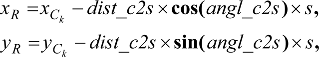
As shown in Fig. 5, the center of the hypotenuse for the right-angled triangular landmark L c is matched to the predetermined position of the sensor node in world coordinates. The center of the captured image I c is nearly matched to the current position of the mobile robot because the camera being used is at the center of the mobile robot. Here, dist_c2s and angl_c2s imply the distance and angle between L c and I c , respectively. After obtaining the image coordinates of a right triangular landmark, the image coordinate (x L c , y L c ) of L c , dist_c2s, and angl_c2s are calculated by the following equations:


In addition, the global localization of the mobile robot can be calculated relative to the world coordinates of the landmarks by matching the center of the image frame to the current position of the mobile robot. The calculation process is explained by the following equations:
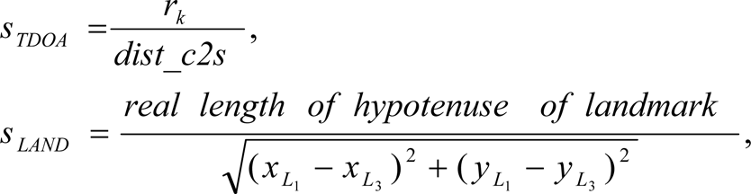

where (x R , y R ) is the current position of the mobile robot, and (x C k , y C k , z C k ) is the three-dimensional absolute position of each sensor node. Here, s is a conversion scale factor that has two types of scale rates: s TDOA is the scale between a real distance from the mobile robot to a sensor node and an image distance, dist_c2s, while s LAND is the scale between the real length and image length of the hypotenuse of the landmark. While s TDOA is used for the conversion scale of normal calculations, s is replaced by s LAND in the abnormal case when TDOA may include the wave's own errors which are caused by multi-paths, collisions, interference, and LOS (line-of-sight) limitations. This may cause critical errors in global localization. If the difference between the measured distance r k and the real distance of dist_c2s which is converted by the hypotenuse length of the landmark is bigger than a specific threshold, s TDOA should be replaced by s LAND . The distance r k in Fig. 3, which is needed to find s TDOA in the proposed localization, can be obtained by

Indoor localization based on landmark image and TDOA distance information.

In general, if a mobile robot can recognize the undistorted distances from more than three sensor nodes, global localization of the mobile robot can be performed by triangulation. However, as mentioned in the previous section, global localization using only wireless electric, RF, or ultrasonic waves can bring about unexpected errors because of the inherent problems of those waves.

Flowchart of the sensor fusion process for global localization.
Therefore, the proposed localization method focuses on overcoming these problems and reducing the computational load of vision-based localization; it enhances the accuracy and robustness of global localization through this mutually complementary combining step.
Correlation between image coordinates and real coordinates in an image frame.
The proposed localization resolves another severe problem that the relative position information of vision-based localization can have some image distortion when the center position of a landmark is located around the edge, far from the center position of the entire frame. In this case, small measurement errors of one or two pixels can result in proportionally larger real-distance errors. If the difference between dist_c2s and an image distance of the real distance r k converted by s LAND is more than a specific threshold value with respect to dist_c2s, dist_c2s is replaced by a new value calculated by interpolating both image distances. This is because the real distance r k is considered to be a more accurate distance measurement when the landmark is distant from the camera.
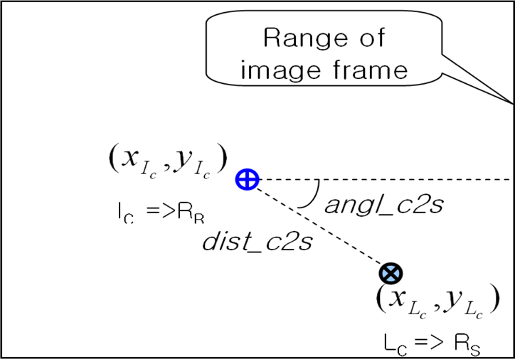
The principal objective of the proposed system is to ensure robust localization in the given dynamic experimental environment by combining the image and distance information obtained by the mobile robot. In general, many experiments are performed in simple indoor office environments such as an open-space office without obstacles even though, in reality, offices and other indoor spaces are usually complex and cluttered. As the test-bed for the experiments, the wheeled mobile robot platform i-Bot (NINETY SYSTEM) was used, as shown in Fig. 6; it was equipped with an ordinary camera and a Cricket listener. A laptop computer with 1.2 GHz processor and Windows XP OS was used for the experiment. Figure 7 shows that it is possible to detect an artificial landmark and calculate the current location regardless of the influence of a fluorescent lamp. The right-angled triangular landmark can be detected by using the well-known labeling algorithm. The image coordinates of landmarks are used to determine the current position of the mobile robot. The real-time localization results of the proposed method are shown in Fig. 8, and the sampling rate is about 5 Hz; the rate depends on the number of labeled areas. The coverage of a sensor node is approximately 3.5 × 2.8m2 (ceiling height: 3 m, angle of view: 30°), and it can differ according to the ceiling height, lens angle of the camera, etc. To verify the position jittering performance, some direct noises were not applied, but this has been suggested to overcome some jittering situations, which can be caused by indirect noises such as the diffusion of fluorescent lamp to result in faulty location calculation.
The geometric direction recognition of right-angled triangular landmarks changes according to each pose of the mobile robot as shown in Fig. 9. As a result, the heading angle is measured by a slope which is made by two endpoints of the hypotenuse of the right-angled triangular landmark in the image coordinates. In addition, the heading error due to general heading sensors such as electric compass or gyroscope is compensated by the heading angle calculated in the image coordinates. The following experiment verified that correct quadrant recognition of landmarks enhances global localization.

Mobile robot platform for the experiment.
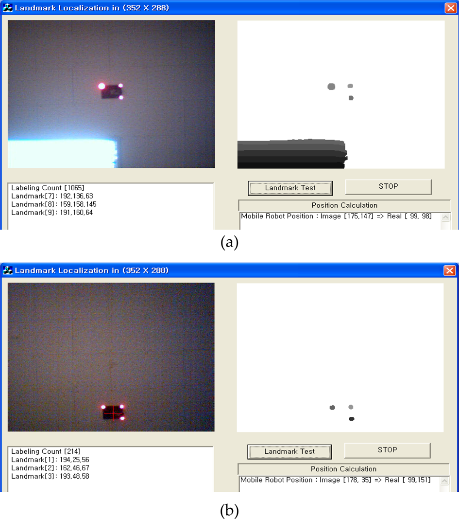
Vision-based localization using landmarks (a)with and (b)without a fluorescent lamp.

Real-time localization operation of the proposed system.

Quadrant recognition of landmarks according to the heading of the mobile robot.
Previous experiments have shown benign results otained under a stable environment. However, various unstable and variant elements exist in real environments. In particular, the results can be very sensitive to fluorescent lamps or other light sources. Figure 10 shows a faulty location calculation because the images might be affected by the diffusion of fluorescent lamp, which leads to many small-sized labeling regions during image processing. To overcome this problem, it is valid and useful to apply fundamental morphology operations such as erosion, dilation, opening, and closing. However, morphology-based image processing consumes additional computation time. The proposed localization applies a simple way to exclude the contaminated area from a full frame image without consuming much computation time. The basic process is first to obtain the coordinates of marginal pixels located at the left-most, right-most, top-most, and bottom-most edges of a region that is labeled by the above predefined size and then, draw a virtual square window using those four coordinates, as shown in Fig. 10. The square window size is then expanded toward each direction by adding a specific size which has been determined by the experimental result. As a result, all cells within the expanded window of the labeled region are not considered for the candidate labeling regions of a landmark. The expansion error in Fig. 11 can occur as a problem to be resolved. This is caused by the assumption that the expanded virtual window can include a normal landmark candidate. Therefore, the labeling size needs to be limited to overcome this problem. The method used segments a widely diffused labeling region like a fluorescent lamp image into several labeling regions. The segmented regions of relatively smaller size are expanded, as shown in Fig. 12. This process was verified to be very efficient for excluding the diffused fluorescent lamp image from a full image and seeking candidate labeling regions of the landmark.

Elimination of many invalid landmark candidates and compensation for faulty localization by expansion of the virtual square window.

Occurrence of expansion error due to a large labeling region.

Solution of expansion error by segmented labeling regions.
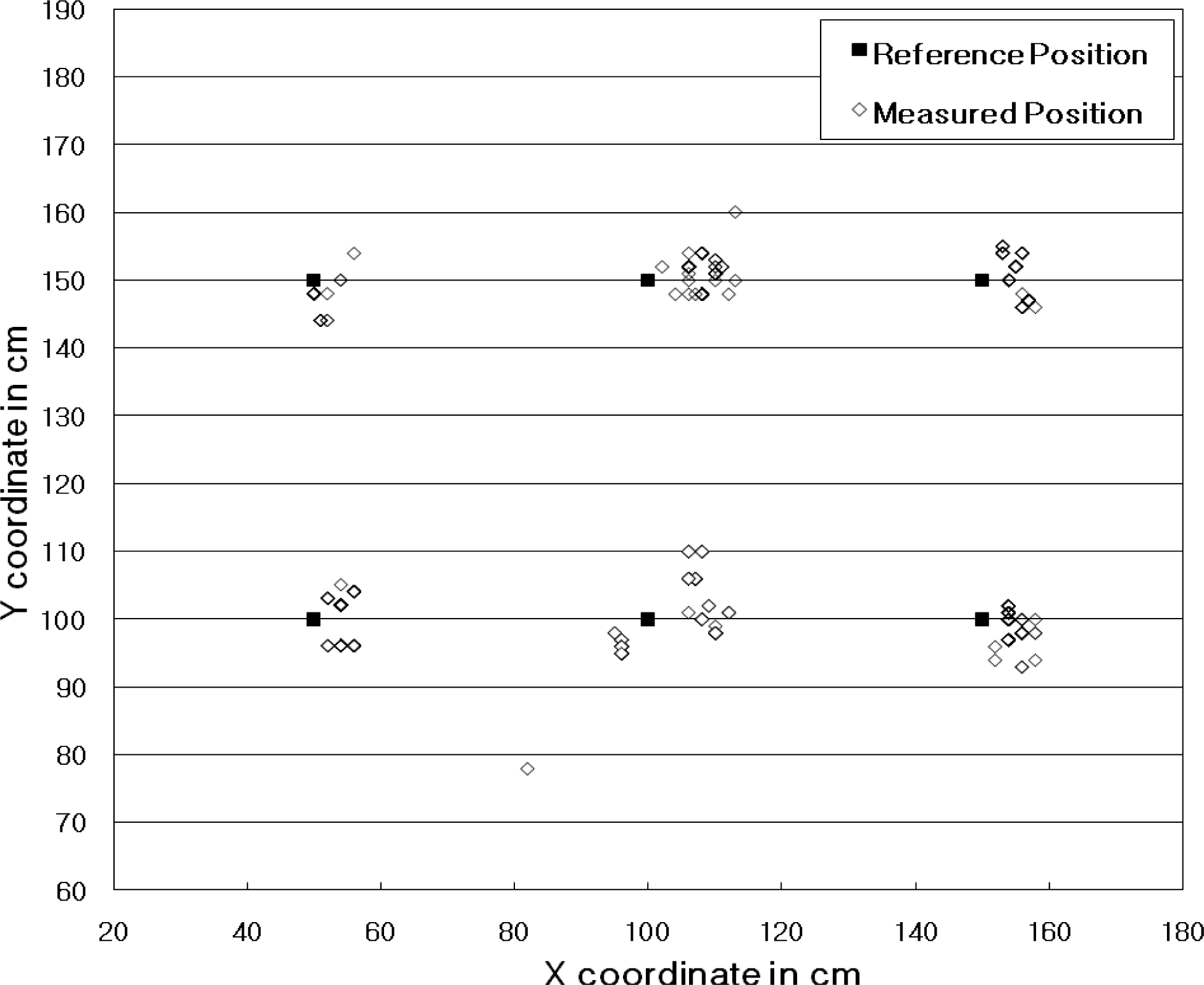
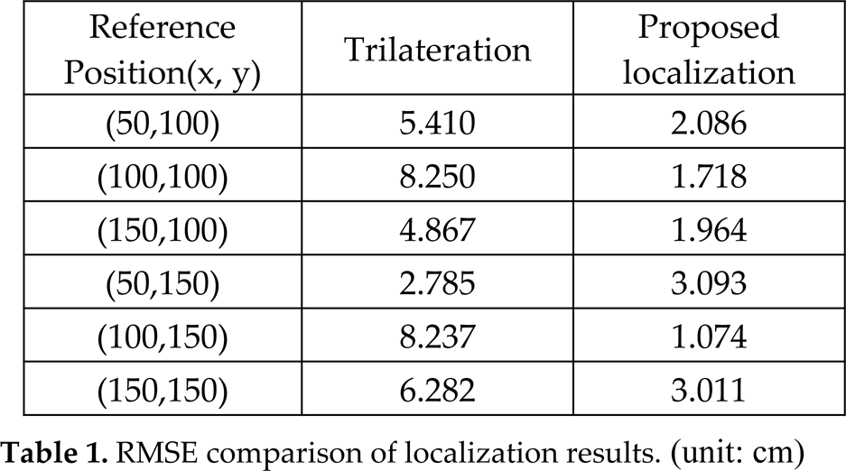
Figures 13 and 14 show the location measurement of each reference position by the triangulation and proposed localization, respectively. The reference positions are marked at regular intervals of 50 cm. We acquired 100 samples of experimental position data at each marked reference position and estimated the position error. Many position errors resulted from the distortion of captured images, and they were especially serious at the edges of the image frame. However, we solved this problem by the mutually complementary combining method for the camera image and the TDOA distance data. In the experiment results, as shown in Table 1, the root mean-square error (RMSE) of the average position errors at each reference position was 2.366 cm. Considering that the RMSE of the measured locations using the trilateration method was about 5.972 cm, the proposed localization presents more enhanced results for indoor localization and guarantees a stable position for the mobile robot to allow for more correct path planning. In addition, Figure 15 shows a real-time movement for tracking a simple straight path (from (100, 50) to (100, 150)) of a mobile robot using the proposed localization method. This experiment shows that the navigation of an assigned path can be achieved within the acceptable position recognition error range within +/-5cm during the real-time movement.
Position measurment by only trilateration of TDOA.

Position measurment of the proposed localization.
RMSE comparison of localization results. (unit: cm)
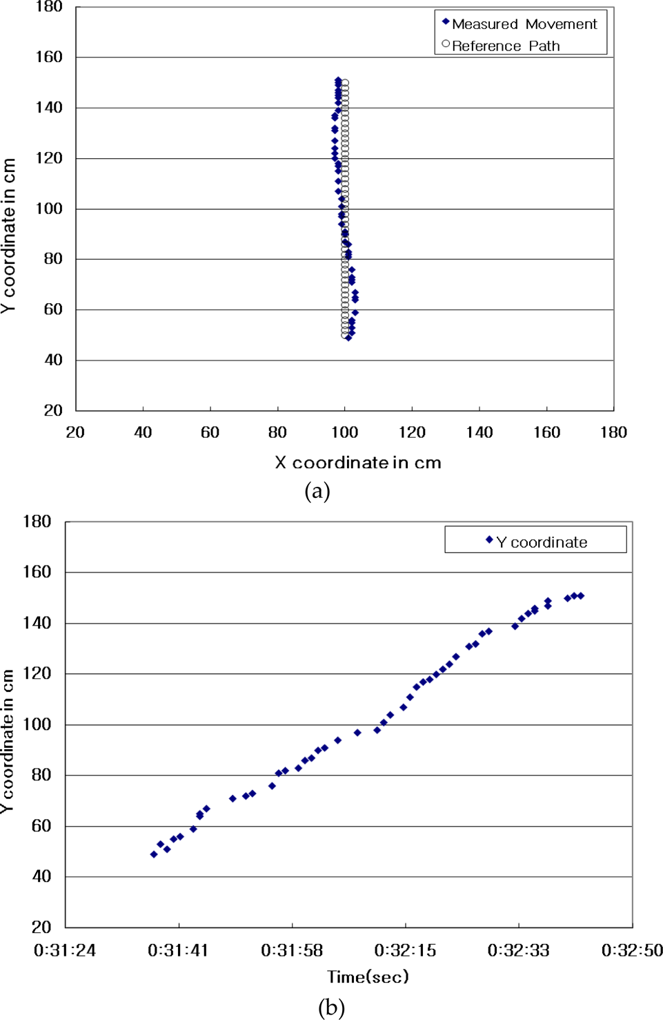
Real-time movement of mobile robot: (a) real positions and (b) Y coordinate according to time change.
We presented a robust localization system which obtains the real position for an indoor service mobile robot by combining simple artificial-landmarks-based image information and TDOA-based distance information. This work has presented a robust localization system that is based on efficiently fusing simple artificial landmark information from vision sensors and TDOA distance information from sensor nodes. The artificial landmark was composed of a sensor node and a right-angled triangular disposition of highly illuminant LEDs. This provides a simple and effective way to find the well-distinctive feature from a full image frame and calculate the relative position and orientation in the image coordinates, And this provides the basis to robustly determine the real position and heading of a mobile robot despite any changes in the surrounding environment. The experimental results showed that the real-time localization and autonomous navigation of a mobile robot can be achieved with enhanced accuracy and robustness during arrival at a target position like a zone where an emergent security event is driven in the proposed home security robot system.
Localization based on a sensor network has additional advantages for indoor service robots because the sensor network can provide additional context-aware indoor information. We proposed a simple artificial landmark model in this paper. In addition, since natural landmarks can also play an important and valuable role in global localization without installation of artificial landmarks, future research will focus on enhancing the proposed vision-based localization by using natural landmarks.
The development of an intelligent service robot system with the capability of automatically recognizing its surroundings and implementing real-time service is underway in our lab using the results obtained in the present study. It is very important for an intelligent robot to be able to implement global localization and autonomous navigation despite environmental constraints. Our future work also will include application of the proposed localization system to home security robot systems based on sensor networks and implementation of a more practical and low-cost home security robot.
Footnotes
6.
This work was supported by the DGIST R&D Program of the Ministry of Education, Science, and Technology (MEST) of Korea(10-BD-0102).