
Abstract
This article addresses the problem of altitude tracking for unmanned aircraft system when the altitude velocity is unknown, because in a practical implementation, the available sensors used to measure the vehicle’s altitude (barometer, global positioning system, laser, etc.) do not provide the altitude velocity. We propose a control strategy based on both the super-twisting sliding mode controller as well as a high-order sliding mode observer to control and to estimate the altitude velocity, respectively. A comprehensive stability analysis for the combined controller–observer based on the Lyapunov stability theory is presented, ensuring the asymptotic convergence of the tracking error under external bounded disturbances. To demonstrate the performance and the effectiveness of the proposed solution, an extensive set of real-time experimental tests performed at outdoor environments is presented.
Introduction
Nowadays, the high level of technology achieved has allowed the development and the application of robotics in more society areas in general. However, with the rise of the robotics applications also there are new challenges to solve. In this context, studies and applications in unmanned aerial systems have been of interest for scientists, engineers, and researchers around the world. With new technologies and theories, the development of unmanned aircraft systems (UASs) has made impressive achievements.
The UASs can be classified into two categories: (i) fixed-wing aircraft and (ii) rotary-wing aircraft. When compared with fixed-wing aircrafts, rotary-wing aircrafts (rotorcrafts, helicopters) have specific characteristics like vertical takeoff and landing in a reduced space. Depending on their shape, rotary-wing aircrafts comprise several types of configurations. A single main rotor aircraft, known as a standard helicopter, is one of the rotary-wing type aircrafts. This kind of aircraft is very hazardous to humans and other objects in an indoor and outdoor environment due to the possibility of collision between the exposed rotor blades and obstacles, causing the aircraft to crash. On the other hand, a quadrotor aircraft is safer in terms of the rotors size, which are smaller and can be enclosed.
In order to improve the quadrotor performance, different control algorithms have been designed and implemented. By itself, the altitude control of a quadrotor helicopter is a challenging problem since the altitude dynamics is coupled with the vehicle’s mass, as well as with the roll and pitch angles, in addition to the disturbances in altitude which can be caused by different factors, such as the rotational dynamics, the change of mass, wind gusts, and so on. Normally, we start with the stabilization of the altitude in order to try to compensate the nonlinear effects in the rest of the translational dynamics 1 ; however, it is crucial that the altitude dynamics converge to desired values even more in finite time.
It is well known that in the case of mini quadrotors, the global positioning system (GPS) and barometer sensors are widely used to measure the vehicle’s altitude. However, altitude velocity can only be available by processing the position data, that is, by filtering, by performing data fusion, or by state estimation. These classical state estimation techniques usually employ the Euler method or different filtering strategies (bandpass or second-order filters or even the Kalman filter) to approximate the velocity measurement. Nevertheless, these approximations are not considered on the stability analysis. Therefore, the most usual output control realization is based on the observer design where the control objective is to bring to zero the error of state estimation.
In the literature, we can find several works that deal with the quadrotor’s altitude control, including the simulation of an adaptive sliding mode controller, 2 a proportional integral controller, 3 and a fuzzy proportional derivative controller with a dynamic feedforward compensator. 4 In addition, experimental applications for altitude control of UASs have been reported; in the study by Wang et al., 5 a linear quadratic Gaussian controller is adopted in order to maintain a relatively constant altitude and a Kalman filter is designed to estimate the altitude velocity. In the study of Alexis et al., 6 a model predictive control for a quadrotor is implemented, using a two-state extended Kalman filter for the estimation of position and velocity altitude. In the study of Luque-Vega et al., 7 a super-twisting sliding mode control applied to the full dynamic of a quadrotor UAS system is presented; however in this approach, it is assumed that the altitude velocity is measured, and neither estimation algorithm nor differentiation technique is considered. A real-time implementation of super-twisting algorithm in a quadrotor is shown by Derafaa et al. 8 , and in this work, the control algorithm is implemented for the attitude vehicle; however, the control altitude problem is not addressed.
Furthermore, many types of observers have been used in order to estimate different variables of the UASs. Research in this area was presented in the study of An et al., 9 where a second-order geometric sliding mode attitude observer is designed for attitude estimation, but the perturbation is not estimated. Similarly, in the study of Benallegue et al., 10 a high-order sliding mode observer works as an observer and estimator of the effect of the external disturbances such as wind and noise of sensors.
Likewise, control strategies based on observers for the stabilization of a UASs have been developed. In the study by Bouadi and Tadjine, 11 a nonlinear observer with a first-order sliding mode control is designed; this observer does not allow to estimate the perturbation of the system. In the study of Besnard et al., 12 a sliding mode control driven by a second-order sliding mode disturbance observer is employed; the observer is used in order to estimate the disturbances but not for estimating the velocities of the system. In the study by Guisser and Medromi, 13 a high-gain observer is designed to estimate the roll and pitching angles online as well as all the linear and angular velocities of the aircraft; however, it does not estimate the perturbations.
Among the techniques employed on these kind of algorithms, the high-order sliding mode observers are widely used due to their finite-time convergence, their insensitivity with respect to uncertainties, and also because they allow to estimate the uncertainties in the model. Based on this fact, several applications of the super-twisting sliding mode controller based on super-twisting observer 14 have been developed. In the study of Filiberto Muñoz et al., 15 we proposed a super-twisting sliding mode controller for altitude control of a quadrotor using a sliding mode observer, but in this work, we only presented simulation results.
Contributions
The main contribution of this article is the real-time implementation of a super-twisting sliding mode controller based on high-order sliding mode observer for the altitude control of an unmanned aerial system in order to obtain robust velocity estimation and robust altitude control. We present a formal mathematical development with the following characteristics: The high-order sliding mode observer allows to estimate, in finite time, the altitude velocity and the external perturbations that affect the system. The super-twisting sliding mode controller enables the UAS to track a desired altitude in the presence of disturbances.
The rest of the article is organized as follows. “Problem statement” section presents the problem statement and introduces the altitude dynamic model of an underactuated quadrotor UAS platform. The super-twisting sliding mode controller based on high-order sliding mode observer and the stability analysis are described in “Design of super-twisting sliding mode controller based on high order sliding mode observer” section. Numerical simulations of the proposed methodology are shown in “Numerical results” section. The employed platform and an extensive set of experimental tests are presented in “Experimental results” section. Finally, the conclusions are presented in the last section.
Problem statement
It is worth mentioning that for the quadrotor UAS, the translational dynamics depend on the orientation angles; therefore, the dynamic model can be divided in to four subsystems 7 : altitude, longitudinal, latitudinal, and heading. In this work, we focus on the altitude subsystem. The adopted dynamic model describing the altitude dynamics of a quadrotor UAS is given as follows 1
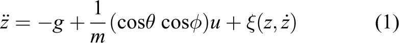
where
The control problem that we want to deal consists on the design and validation of a robust control law u such that the system output z can track a given reference
Design of super-twisting sliding mode controller based on high-order sliding mode observer
The proposed control strategy consists on the development of a super-twisting sliding mode controller based on high-order sliding mode observer. Introducing a new state vector x whose components are defined as

High-order sliding mode observer
The high-order sliding mode observer used to estimate the states for system (2) is given as

where

Defining a new estimation error variable

The dynamics of the estimation error, presented in equation (4), have the form of a non-recursive exact robust differentiator; therefore, the errors
Super-twisting sliding mode controller
The controller is designed in order to obtain the error tracking dynamics in the form of the super-twisting sliding mode controller with the objective of enforcing the sliding mode on the manifold

where the tracking error e is defined as

and finally, by substituting the dynamics of equation (3), it yields

Let the control input u be defined as follows

where θ and φ are bounded in the interval

Defining

Remark 1
Equation (5) was derived by using the dynamics of
Theorem 1
Suppose that for system (1), the derivative of the perturbation is bounded, that is,
Proof
A sketch of the proof is presented below. The complete proof of the theorem can be found in the works of Moreno and Osorio 17 and Shtessel et al., 18 Introducing a new state vector, ν is defined as

The system (7) is written in matrix form as follows

Remark
If
The following Lyapunov function candidate is introduced in order to prove the convergence of

which can be rewritten as

with

the matrix P is positive definite if
Remark 2
The function V is continuous but not locally Lipschitz; for this reason, the usual second method of Lyapunov is not valid. In the study of Moreno and Osorio, 17 all the conditions required by the Zubov’s theorem were obtained for the proposed Lyapunov candidate function. Therefore, we can continue the Lyapunov analysis following these ideas. For those points where the derivative does not exist, the arguments presented by Poznyak 19 and Salgado et al. 20 are employed.
The temporal derivative of equation (9) is given as

with
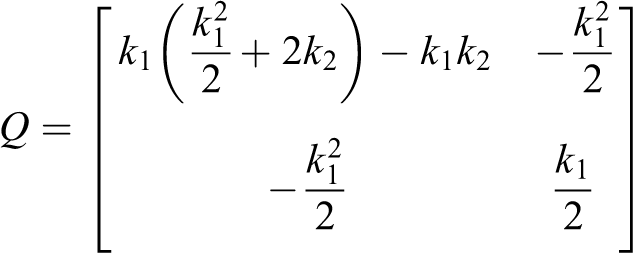
The matrix Q will be positive definite if the gains


Equation (10) is given by

with γ defined as

From equation (13), it can be seen that

providing asymptotic convergence of the tracking error.
Numerical results
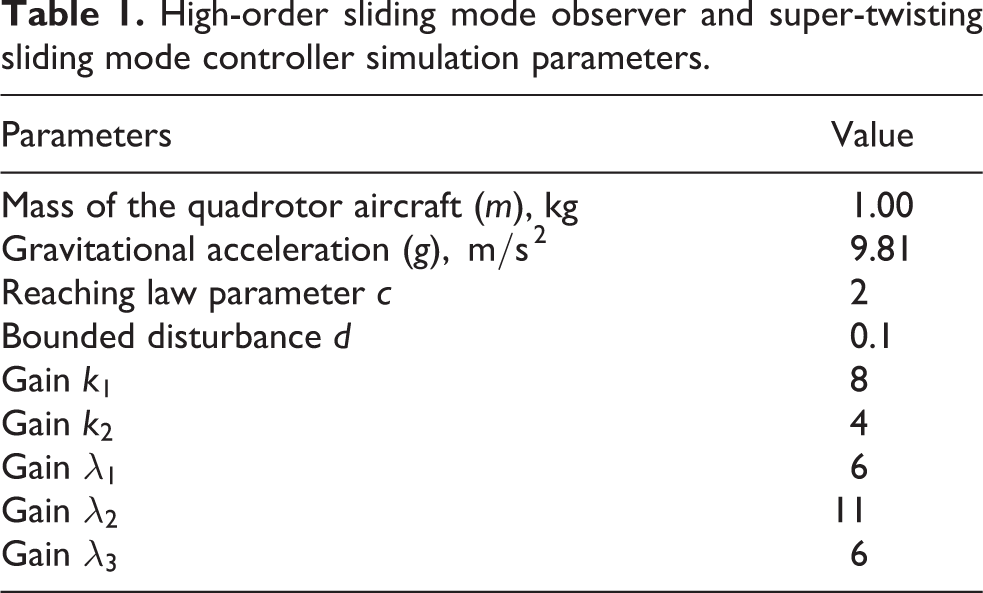
The numerical results of the simulation of a super-twisting sliding mode controller based on high-order sliding mode observer on a quadrotor aircraft are presented below in order to verify the estimated speed of the z-dynamic (altitude) for the aerial vehicle. A short list of the parameters used in the simulation of the high-order sliding mode observer is briefly described in Table 1.
High-order sliding mode observer and super-twisting sliding mode controller simulation parameters.
In order to test the robustness of the controller–observer algorithm and carry out a more realistic simulation, the following disturbances were applied to the altitude mathematical model given by equation (2): A Dryden wind gust model is added to the system; an extensive description of this model can be found in the work of Waslander and Wang.
21
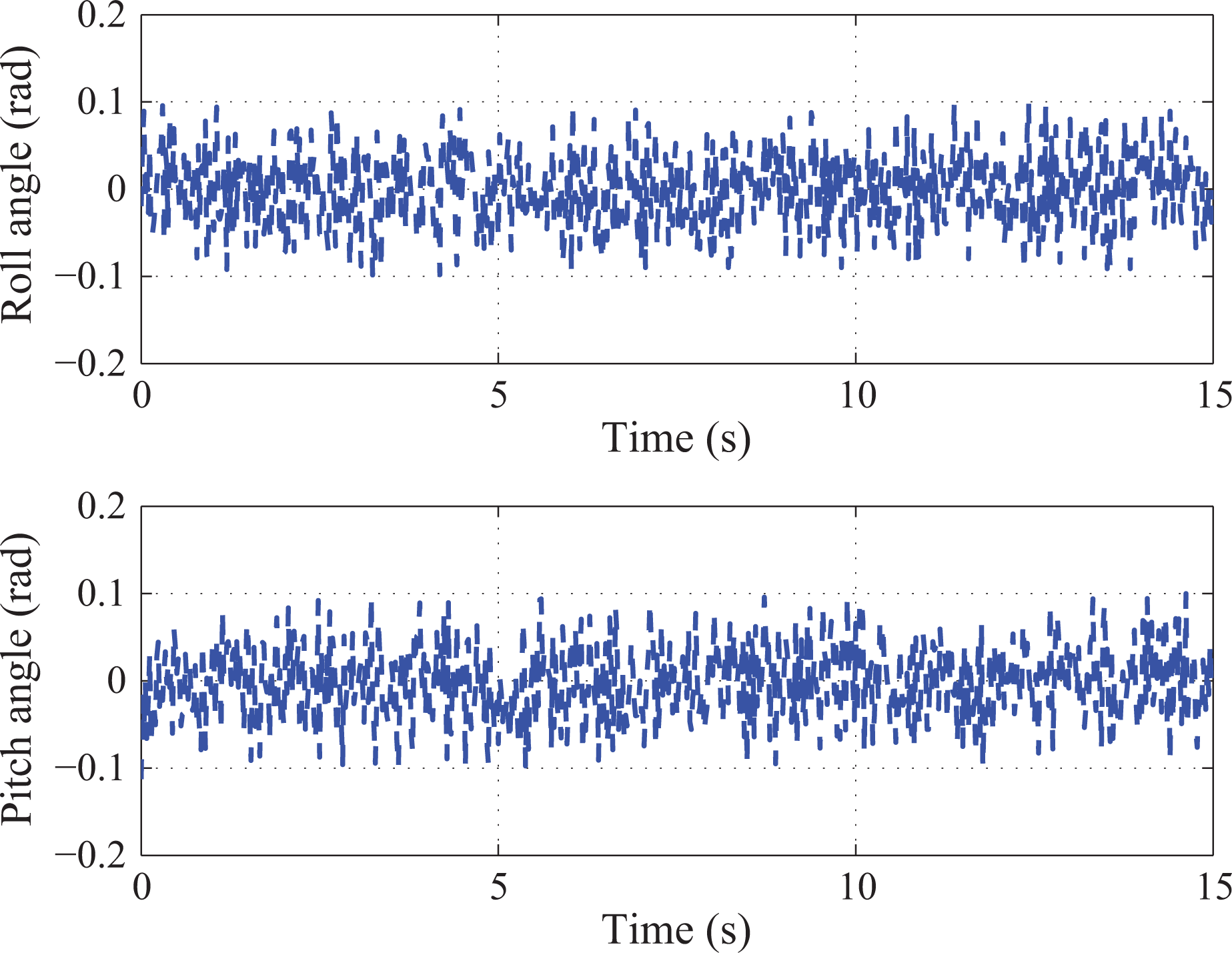
The mathematical Dryden wind gust model is given as follows where In practice, the roll and pitch angles are not equal to zero, because of noise of inertial measurement unit and by wind disturbances. For this reason, in this simulation, a noise was added to the angles of roll (φ) and pitch (θ). The roll and pitch angles are ranged from −0.1 to 0.1 rad. Finally, a Gaussian noise was added to the altitude variable

Figures 1
to 6 show the performance of the high-order sliding mode observer in the reconstruction of the system states variables, as well as the estimation of the proposed disturbance. We can see that the goal, consisting on the estimation of the vehicle’s velocity and position in the z-axis, was achieved successfully. This performance allowed us to control the altitude of the quadrotor aircraft at a given reference. In Figure 1, it can be observed that the estimated altitude of the quadrotor aircraft quickly converges to the real altitude using the high-order sliding mode observer. Afterward, once the estimated altitude converges to the real altitude in finite time, the observer follows exactly the original signal although there are changes in the real altitude (e.g.

Real position

Real velocity
Moreover, Figure 3 shows the control signal applied to the UAS, and Figure 4 depicts the reconstruction of the Dryden wind gust model

Control signal

Wind gust disturbance, real and estimated.
The estimation errors of the vehicle’s position and the velocity altitude are depicted in Figure 5, where it can be appreciated that the estimation errors converge to zero in finite time. Figure 6 shows the sliding manifold s, notice that the sliding manifold converges to zero in finite time implying that the tracking errors e and

Estimation errors of position (

Evolution of the sliding manifold.
Added disturbances in the roll and the pitch angles.
Experimental results
In this section, the experimental results are provided to demonstrate the effectiveness of the proposed high-order sliding mode observer to estimate the velocity in the z-axis of a quadrotor aircraft. We have used a quantitative approach to choose the parameters of the sliding mode observer, which was implemented in outdoor environment.
Experimental platform
The experimental platform used to implement the super-twisting sliding mode controller based on high-order sliding mode observer consists on a quadrotor aircraft which uses a LIDAR-Lite Laser Rangefinder (Garmin International, Inc., Olathe) (see Figure 8) to obtain the measurement of the vehicle’s altitude. The autopilot employed was the embedded high-performance all-in-one system Pixhawk, which has integrated a three-axis gyroscope, three-axis accelerometer, magnetometer, compass, and barometer sensor. This autopilot includes serial, I2C, and SPI ports, which can be used for GPS and telemetry. Additionally, the Pixhawk module has a NuttX real-time operating system. The autopilot runs the developed control algorithms in real time to stabilize the quadrotor system managing the information provided by the laser sensor and sends the control signals to the four motors. The quadrotor aircraft is built with the following components: a carbon fiber frame of 550 mm, four Multistar brushless motors model 4220-650Kv (Turnigy power systems by HobbyKing Online Hobby Store. Hong Kong, China) of 16 poles, four carbon fiber propellers of 11 inches of diameter and a pitch of 4.7 inches, and a LiPo battery (Turnigy power systems by HobbyKing Online Hobby Store. Hong Kong, China) of three cells at 3300 mAh. Finally, a Futaba 2.4 GHz FASST (FUTABA Corporation, Japan) radio transmitter system was used to specify the altitude set points in order to verify the controller’s performance at different distances.

Quadrotor aircraft platform with the LIDAR-Lite Laser Rangefinder (LIDAR-Lite v2) used to test the performance of the high-order sliding mode observer.
Table 2 shows the platform’s physical parameters, where constant d means the distance between the center of mass of the quadrotor helicopter and any of the four brushless DC (BLDC) motors attached to the end of the frame, while
Quadrotor aircraft physical parameters.

We have used the Laser Rangefinder by PulsedLight model LIDAR-Lite v2 since the autopilot’s embedded pressure sensor (barometer) delivers noisy height measurements causing bad velocity estimation and a poor performance of the altitude controller. This laser sensor can be interfaced via I2C or PWM to the quadrotor’s autopilot and mounted to the vehicle’s frame as shown in Figure 8. Moreover, the sensor has been designed to operate effectively under a variety of different ground conditions and bright outdoor solar background lighting conditions. The internal optical absorption filter in combination with the detector spectral response provides a transmission band from
As it can be seen in Figures 9 and 10, the set of experiments were conducted in a soccer game field, which allowed us to realize the experiments under safe conditions at outdoor environments. In Figure 9, it is possible to observe the quadrotor in flight, which is maintained autonomously at an altitude of 1 m by using the super-twisting sliding mode controller based on high-order sliding mode observer. Finally, Figure 10 shows the quadrotor flying autonomously at 2 m of altitude.
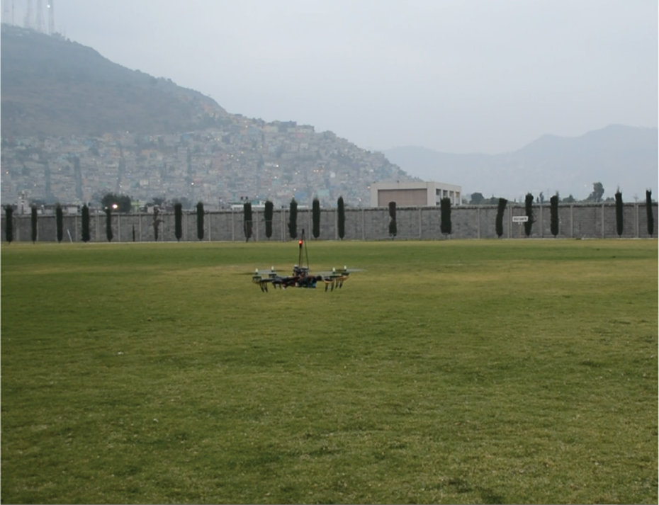
Quadrotor at altitude of 1 m.

Quadrotor at altitude of 2 m.
Figure 11 depicts a comparison of the measurements obtained from both sensors, where we can observe the big difference in the quality of the measurements that delivers each sensor. Since the measurement of the laser sensor is much more accurate than the one obtained from the barometer, it is not necessary to implement an additional filtering stage, which enables the development and implementation of robust observers. Also, it can be seen from Figure 11 that the test time starts at
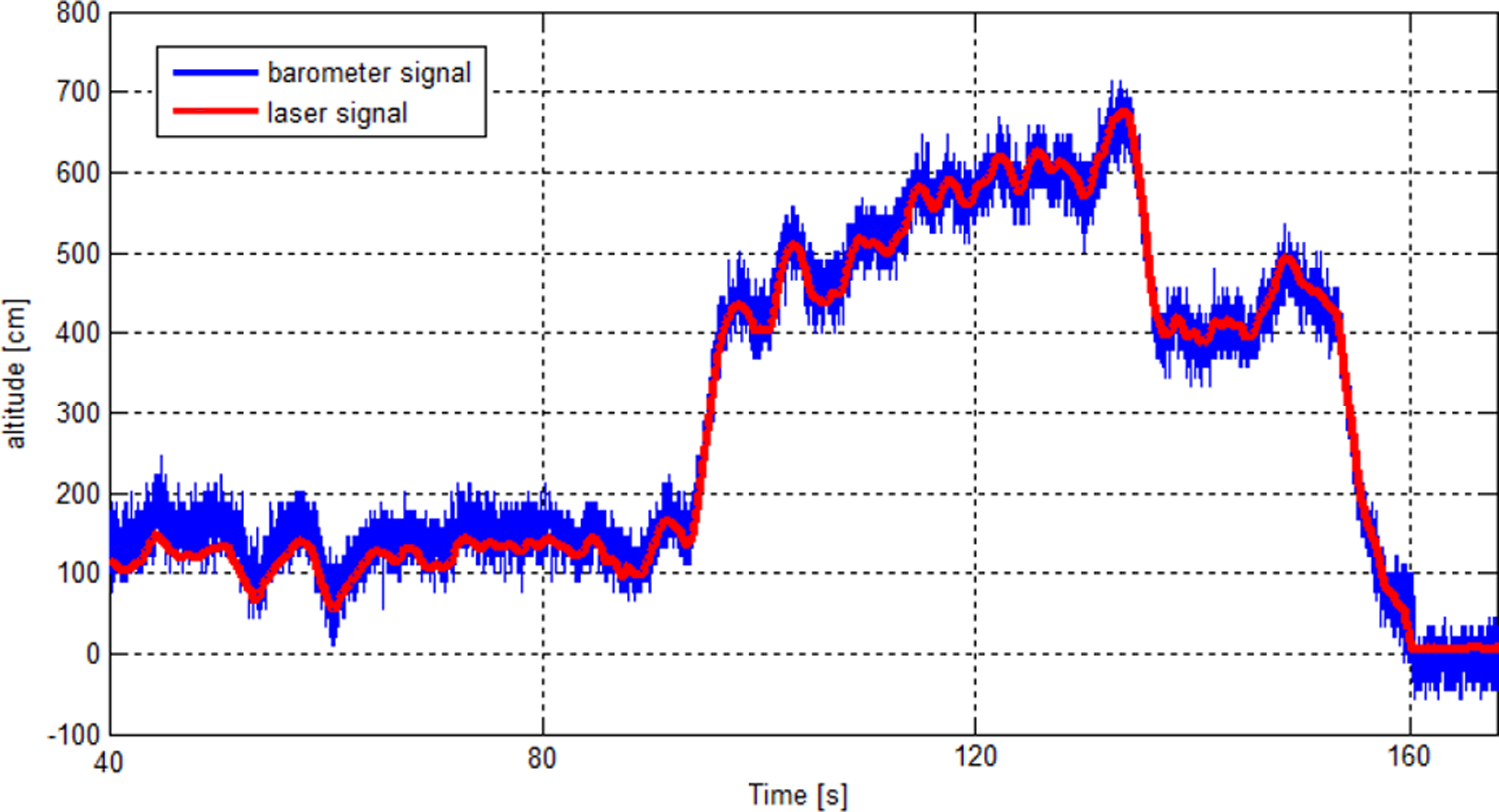
Measurement comparison between the barometer and the laser rangefinder.
To analyze the effectiveness and the robustness of the proposed algorithm, we have performed a set of five experimental tests in outdoor environments where it was developed a comparison between the obtained results for velocity estimation by using the sliding mode observer against the ones obtained by using a Levant’s differentiator. We have decided to use the Levant’s algorithm (as a reference to demonstrate the proper functioning of the proposed high-order sliding mode observer) due to the good performance presented by this numerical differentiator to obtain an estimation of the velocity when only the position measurement is available. In experiment no. 1, the desired aircraft’s altitude at 1 m with added external disturbances was defined. In experiment no. 2, the desired reference was defined at 2 m, and the initial condition for the vehicle’s altitude was defined as
The controllers’ parameters were tuned by performing simulation and experimental tests, until obtaining a better performance of the quadrotor’s response. Figures 12 to 21 show the experimental results obtained from the set of experiments where it was implemented the high-order sliding mode observer to demonstrate its efficiency under different initial conditions and under induced external disturbances. The complete list of experimental parameters employed in tuning the robust observer and the altitude controller is shown in Table 3.
Real-time altitude position with a reference of 1 m using the high-order sliding mode observer in outdoor environments.
Experimental parameters for high-order sliding mode observer and super-twisting sliding mode controller.

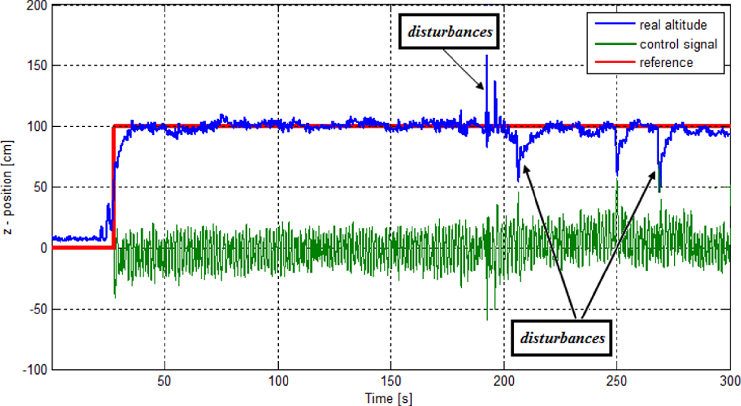
Experiment no. 1: Altitude control at 1 m under induced disturbances
In this experiment, the high-order sliding mode observer is used to estimate the velocity in the quadrotor’s z-axis in order to use it in the controller stage that allows the vehicle to reach the desired reference at 1 m under induced external disturbances. Figure 12 illustrates the vehicle altitude’s behavior and the corresponding control signal (green line) obtained in this test. Furthermore, we can see that the aircraft remains stable even when the vehicle’s altitude is externally disturbed to explore the disturbance rejection performance around the desired set point. Figure 13 shows a comparison between the obtained velocity response using the Levant’s differentiator and the obtained velocity using the high-order sliding mode observer, respectively. It can be seen that the signal of the velocity estimation obtained using the high-order sliding mode observer compared to the one obtained from the Levant’s differentiator is very similar indicating a proper tuning of the observer’s parameters.
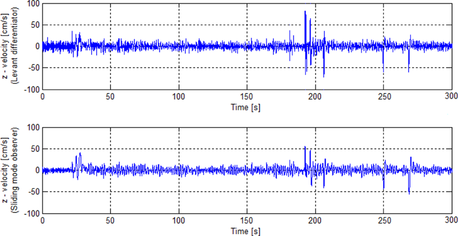
Comparison between the velocity obtained by using Levant’s algorithm versus the velocity obtained by using the high-order sliding mode observer.
Experiment no. 2: Altitude control at 2 m under induced disturbances
Figure 14 illustrates the behavior of the vehicle’s altitude when it is commanded to reach a desired reference of 2 m using the high-order sliding mode observer, as well as its corresponding control signal (green line). As in the previous experiment, it is possible to notice the performance of altitude controller under external disturbances deliberately induced in outdoor environment, which is a result of a good estimation of the altitude velocity. On the other hand, Figure 15 shows the comparison between the velocity obtained using the Levant’s differentiator and the velocity obtained using the high-order sliding mode observer, respectively.

Real-time altitude position with a reference of 2 m using the high-order sliding mode observer in outdoor environment.

Comparison between the velocity obtained by using the Levant’s differentiator versus the velocity obtained by using the high-order sliding mode observer when considering induced disturbances.
Experiment no. 3: Tracking of a square wave without induced disturbances
Figure 16 shows the altitude response when the reference signal is a square wave with a period equal to

Tracking of a square wave using the high-order sliding mode observer in an outdoor environment without considering induced disturbances.

Comparison between the velocity obtained by using the Levant’s differentiator versus the velocity obtained by using the high-order sliding mode observer a square signal.
Experiment no. 4: Tracking of a square wave under induced disturbances
In this experiment, tracking of a square signal under induced disturbances was performed. Figures 18 and 19 show the z-position and the velocity estimation, as well as the corresponding control input (green line), respectively. As we can see, the results obtained in this experiment are similar to the ones obtained in the previous experiment; however, in this instance, the quadrotor aircraft has been subjected to disturbances at different time instants in order to evaluate the performance of both the proposed high-order sliding mode observer as well as the super-twisting sliding mode controller. We can see from Figure 19 that the signal obtained using the high-order sliding mode observer allows to get a good performance of the super-twisting sliding mode controller even under adverse conditions such as bounded wind gusts.
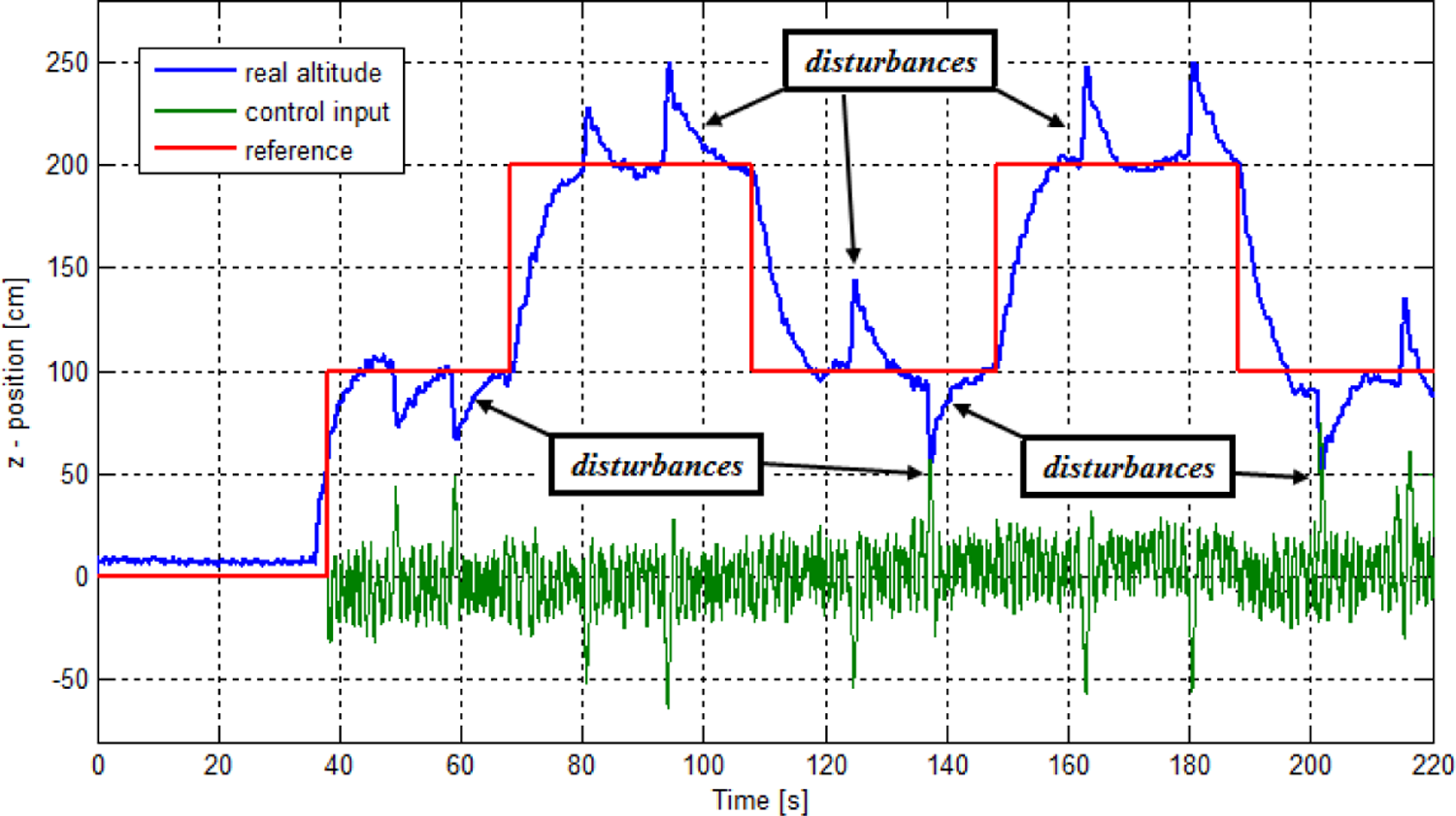
Tracking of a square wave using the high-order sliding mode observer in an outdoor environment while considering induced disturbances.

Comparison between the velocity obtained by using the Levant’s differentiator versus the velocity obtained by using the high-order sliding mode observer while tracking a square signal under induced disturbances.
Experiment no. 5: Altitude tracking at different set points
Figures 20 and 21 illustrate the response of the quadrotor’s altitude at different reference values, as well as the velocity estimation using the Levant’s differentiator and the high-order sliding mode observer in outdoor environments, respectively. We can see that the response at the different references values is satisfactory, demonstrating the effectiveness of real-time super-twisting sliding mode controller under induced disturbances while using the estimation provided by the high-order sliding mode observer.

Altitude tracking of different set points up to 10 m using the high-order sliding mode observer in outdoor environments.
To explore the effectiveness and the robustness of the proposed super-twisting sliding mode controller, it has been considered a test outdoor (like other previous experiments) which consists of a change in mass of the quadrotor aircraft during a flight in hovering mode. Figure 22 illustrates a mass change example of our aerial vehicle using the high-order sliding mode observer. For this test, we have added

Comparison between the velocity obtained by using the Levant’s differentiator versus the velocity obtained by using the high-order sliding mode observer while tracking different set points.

Altitude behavior under perturbations added mass change in outdoor environment.
Conclusions
As it was expected, the implementation of the laser rangefinder showed a better performance of the altitude measurement compared with measurement obtained from the barometer. The combination of the super-twisting sliding mode controller and the high-order sliding mode observer allowed us to control the altitude position and velocity of the UAS. From the simulation and experimental results, it was shown that the high-order sliding mode observer allowed us to estimate the altitude velocity and to estimate the disturbances that affect to the system’s behavior. By using the information provided by the high-order sliding mode observer, the super-twisting sliding mode controller showed a satisfactory performance enabling the UAS to track a given reference. Finally, the extensive set of performed experiments allowed us to validate the proposed controller at different set points and under induced disturbances.
Footnotes
Declaration of conflicting interests
The author(s) declared no potential conflicts of interest with respect to the research, authorship, and/or publication of this article.
Funding
The author(s) disclosed receipt of the following financial support for the research, authorship, and/or publication of this article: This work was partially supported by the Mexican Secretariat of Public Education (SEP) Grant PRODEP UPPACH-004 and by the Project Red Temática de Sistemas Autónomos y Ciber-Físicos.