
Abstract
Tilt-rotor unmanned aerial vehicles have attracted increasing attention due to their ability to perform vertical take-off and landing and their high-speed cruising abilities, thereby presenting broad application prospects. Considering portability and applications in tasks characterized by constrained or small scope areas, this article presents a compact tricopter configuration tilt-rotor unmanned aerial vehicle with full modes of flight from the rotor mode to the fixed-wing mode and vice versa. The unique multiple modes make the tilt-rotor unmanned aerial vehicle a multi-input multi-output, non-affine, multi-channel cross coupling, and nonlinear system. Considering these characteristics, a control allocation method is designed to make the controller adaptive to the full modes of flight. To reduce the cost, the accurate dynamic model of the tilt-rotor unmanned aerial vehicle is not obtained, so a full-mode flight strategy is designed in view of this situation. An autonomous flight test was conducted, and the results indicate the satisfactory performance of the control allocation method and flight strategy.
Introduction
Vertical take-off and landing unmanned aerial vehicles (VTOL UAVs) have become a focus of UAV research. Compared with rotor UAVs, VTOL UAVs can be used in scenarios that require higher speeds, longer flight ranges, or larger payload capacities. Compared with fixed-wing UAVs, VTOL UAVs could be used without the need of runway which extend application domain. Considered to be a promising VTOL configuration, the tiltrotor UAV is actively researched in the field of academics and industry due to the controllability and stability in vertical flight. 1 Some large-scale examples of such tilt-rotor UAVs include the Bell Eagle Eye, 2 SMART UAV 3 developed by the Korea Aerospace Research Institute, and the IAI Panther. 4 Moreover, many smaller scale tilt-rotor UAVs have been developed, including FireFLY6, 5 Orange Hawk, 6 TURAC, 7 and TRON 8 shown in Figure 1.
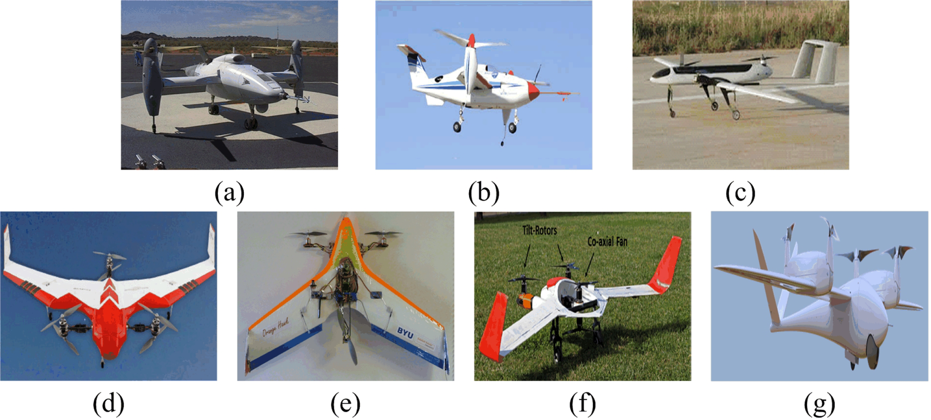
Examples of tiltrotor UAVs. (a) Bell Eagle Eye, (b) SMART UAV, (c) Panther, (d) FireFLY6, (e) Orange Hawk, (f) TURAC, and (g) TRON. UAVs: unmanned aerial vehicles.
Aiming at the applications in tasks characterized by constrained or small scope areas such as power line inspection, urban traffic supervision, earthquake disaster area reconnaissance, and express delivery in mountainous regions, this article proposes a compact electrically powered tilt-rotor UAV, the main parameters of which are listed in Table 1. The tilt-rotor UAV adopts a tricopter configuration and compared with the dual propeller configuration, which requires cyclic control, the tricopter configuration reduces the mechanical complexity and control difficulty. Compared with other multi-rotor configurations, the number of actuators is reduced, which means lower cost, increased energy savings, and longer flight durations. There are several unique features in the structural design that distinguishes this work from other tricopter UAVs found in the literature. In the tricopter configuration, the yaw moment that causes unstable motion induced by the reaction torque from the unpaired rotors is resolved using a rear coaxial rotor, as in TURAC and using all three coaxial rotors as in FireFLY6. However, both configurations increase the number of rotors, which will eliminate the advantage of the tricopter configuration compared with the multi-rotor configuration. The tilt-rotor UAV proposed in this work balances the yaw moment via the differential tilting of the front rotors, as in IAI Panther 4 that does not increase the number of actuators. Compared with mini IAI Panther 4 and IAI Panther, the proposed tilt-rotor UAV is a more compact and light-weight platform, which ensures that it is man-portable, with a wingspan of 1.7 m versus wingspans of 3.5 and 8 m and a weight of 3.33 kg versus weights of 12 and 65 kg.
Specifications of the tilt-rotor UAV.

UAVs: unmanned aerial vehicles.
The ability to realize multi-mode flight brings about many benefits; however, it also poses certain challenges for the problem of control. The actuators and control logic in different flight modes are different, the control weights of the rotor and fixed-wing modes need to be distributed based on efficiency, and control must be allocated to different actuators based on the control logic during the transition process. The thrust vector varies during the transition process, leading to a non-affine system and introducing dramatic cross coupling effects between the pitch, roll, yaw, and thrust channels. This is in contrast to ordinary fixed-wing UAVs, which can decouple the vertical and lateral channels. Moreover, the induced airflow varies due to tilting during the transition, aggravating the system nonlinearity and uncertainty of the mode. These features make it difficult to build an accurate mathematical model.
Considering these challenges, many scholars have conducted numerous related studies in the simulation environment. Rysdyk and Calise 9 applied a neural network (NN)-augmented model inversion control to the longitudinal channel of the generic tilt-rotor simulator; however, the control characteristics of the transition flight were not discussed. Kang et al. 10 took 40% scale smart UAV model as an object and designed an NN adaptive controller for the outer speed loop and the inner attitude loop. The simulation results of the autonomous waypoint guidance showed that the UAV could fly in the full flight envelope, including automatic conversion and reconversion under turbulent wind conditions. Kim et al. 11 adopted dynamic inversion applied to both inner loop stability and control augmentation system (SCAS) and an outer loop trajectory tracking system based on the time scale separation approach. The simulation verified the stability of the hovering mode and performance of the trajectory tracking from the fixed-wing mode to the rotor mode without full-mode flight. Chowdhury et al. 12 designed a backstepping-based proportional-derivative (PD) controller for position and attitude control. The simulation results demonstrated stabilization in a hovering experiment and ensured the convergence of the system in a tracking experiment; however, the dynamic mode ignored the aerodynamics of the airframe. Jin et al. 13 proposed a manipulation assignment strategy of full-mode flight by trim analysis and adopted the proportional–integral–derivative (PID) controller for each channel. The simulation showed the process of the full-mode flight had little fluctuation in attitude and velocities. Some researches are conducted in the actual flight experiment. Yuksek et al. 7 successively designed a cascade control system including angular rate feedback, attitude feedback, and speed feedback and adopted a PID controller for the roll, pitch, and yaw channels. A flight experiment demonstrated a hover to transition maneuver. Kang et al. 14 –16 combined a rotor governor for a constant rotor speed and attitude SCAS feedback PID controller to ensure stability of the roll, pitch, and yaw channels as the most basic control logics. The flight experiment realized the full autonomous flight from take-off to landing by tracking a curve inside the conversion corridor. However, the establishment of the conversion corridor required an accurate model via wind tunnel testing, which is expensive. Jiandong et al. 17 designed an explicit model following control system and H ∞ loop shaping design procedure for different flight modes and adopted multi-model adaptive control to switch between different control laws. Simulations and full-mode flight test verified the effectiveness of the control method; however, the research also established the aerodynamics of the UAV and determined full-mode flight strategy based on wind tunnel testing.
As reviewed earlier, most studies are based on simulations, few studies that have evolved to flight testing adopt the PID method in full-mode flight. However, these studies rely on accurate models, which are expensive to achieve. In view of that, realizing full-mode autonomous flight without an accurate model to reduce the cost motivates this work. This work adopts a PID method for controlling the attitude as well. Moreover, considering that the number of actuators is not equal to the number of control channels in the rotor mode and transition process, direct inversion cannot be applied; in addition, the control system is not input-affine, which increases the difficulty of control allocation. This will aggravate multi-channel coupling and the control error if control allocation is not properly addressed. Many control allocation strategies have been proposed such as direct control allocation, 18 pseudo inverse, 19 a daisy chaining logic, 20 linear programming, 21 and quadratic programming. 22 Considering the feature of the proposed tilt-rotor UAV, a control allocation method that can reduce the inaccuracy of the pseudo inverse method and be less complex than linear programming or quadratic programming methods is designed to make the mixer adaptive to the full-mode flight.
The major contributions of this article are as follows: First, we construct a tricopter configuration tilt-rotor UAV prototype, which reduce the number of actuators and is more portable and compact, compared to other UAVs with the same configuration; second, we design a full-mode flight strategy realizing full-mode autonomous flight without an accurate dynamic model; and finally, we design a control allocation method to make the controller adaptive to full-mode flight better.
The remainder of this article is organized as follows. The second section presents the tilt-rotor UAV prototype. In the third section, the flight control design is provided. The actual flight experiment is implemented in the fourth section. Finally, the conclusion and future work are discussed in the fifth section.
The tilt-rotor UAV platform
The partial experimental settings of the tilt-rotor UAV platform are shown in Figure 2. The platform consists of the onboard section, which includes the UAV frame and autopilot, and the ground section, which includes a ground station and a remote controller.

Block diagram of the experimental flight system.
The autopilot can measure the flight states, send the states to the ground station, and control the flight of the UAV. The autopilot adopts the Pixhawk autopilot system made by 3DRobotics, which is an independent, open-source, open-hardware project. The Pixhawk system, running the NuttX (version 6.18) real-time operating system, utilizes a 168 MHz CortexM4FARM processor and has 256 KB of RAM and 2 MB of flash memory. 23 The system has 14 pulse-width modulation (PWM) servo outputs. The onboard sensors include an IMU, a GPS module with data updated at 5 Hz, a barometer, and a digital airspeed sensor. The UAV can be guided by both autopilot and a pilot. If the pilot finds the UAV in an abnormal flight manner, the control is switched to the remote controller using a Futaba<001> T14SG 2.4 GHz transmitter to make the UAV restore safe flight. The ground station software “QGroundControl” 24 is open-source ground control software compatible with the Pixhawk autopilot. The ground station is used to observe the flight status of the UAV and configure and control the UAV by sending commands to the autopilot through the data link with a radio frequency of 900 MHz.
The proposed tilt-rotor UAV features a conventional aileron, elevator control surface configuration, three fixed-pitch rotors, and two servo motors. The two front rotors can tilt from vertical to horizontal positions with a tilting mechanism that is driven by two servo motor, as shown in Figure 3. The tail rotor is fixed at the rear of the vehicle vertically. When the front rotors are in the vertical position, the tilt-rotor UAV is in rotor mode. The control scheme of the rotor mode is shown in Figure 3. The roll is controlled via the differential thrusting of the two front rotors, and the pitch is controlled via the differential thrusting of the front and tail rotors. To balance the yaw moment induced by the reaction torque from the unpaired rotor, the yaw is controlled via the differential tilting of the front rotors.
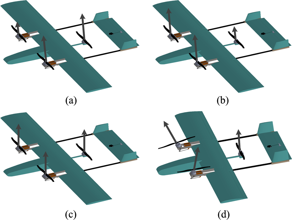
Control logic in rotor mode. (a) roll, (b) pitch, (c) thrust, and (d) yaw.
When the front rotors are in the horizontal position, the front rotors only offer thrust along the longitudinal axis. With the tail rotor off, the tilt-rotor UAV is in the fixed-wing mode. The control scheme in the fixed-wing mode is similar to that of the conventional fixed-wing UAV. The roll channel is controlled by the aileron, the pitch channel is controlled by the elevator, the speed channel is controlled by the speed of the motors, and the yaw channel is controlled by the aileron because there is no rudder installed, considering that the rudder is not frequently used. The transition from the rotor mode to the fixed-wing mode is called the conversion mode. The transition from the fixed-wing mode to the rotor mode is called the reconversion mode. The different flight modes are shown in Figure 4.

Different flight modes. (a) The fixed-wing mode, (b) conversion or reconversion mode, and (c) the rotor mode.
If the tilting mechanisms are installed at both ends of the wing, the wing structure needs to be strengthened. To reduce the vibration of the wing caused by the tilting mechanism and to reduce the weight of the wing, the positions of the tilting mechanisms are designed to be as close as possible to the body, and the center of gravity is required to be as close as possible to the center of the triangle formed by the three rotors. The vertical and horizontal tails are of a light wood material to reduce weight, and other structures of the prototype are of a multilayer board material. The motors are T-motor MN5208. The motor–rotor couples are tested on a test bench to calculate the thrust and torque coefficient. As a result of these tests, the appropriate rotor size is chosen as 16 × 5.4 in.
Flight control system design
Full-mode flight strategy
In autonomous flight, the ground control station gives a take off command. The UAV flies along a predetermined flight path by autopilot. The switching between different flight modes is triggered by a predetermined flight point. The specific process is shown in Figure 5.

Flight mission profile.
Point H is the take-off and landing point. The tilt-rotor UAV takes off in the rotor mode to maintain a stable attitude and climbs vertically at a fixed speed. After reaching the specified altitude point 1, the tilt-rotor UAV adjusts the yaw angle so that the head points to the intended direction of flight. After adjusting the direction, the tilt-rotor UAV flies toward flight point 2, and flight point 2 triggers the conversion command. The conversion mode consists of stages P1 and P2. In stage P1, the tilt-rotor makes a negative pitch angle θ to accelerate; meanwhile, the rotors begin to tilt at a fixed rate until a preset maximum tilting angle. When the switching speed is reached, the tilt-rotor UAV is into stage P2. The rotors first stop, and then, the tilt-rotor UAV instantaneously switches to the fixed-wing mode. Once in the fixed-wing mode, rotors 1 and 2 accelerate to ensure that the airspeed remains above the stall speed with a large throttle for a period of time, and rotor 3 stops running. If, in conversion mode, the UAV remains unable to accelerate to the switching speed for 5 s, the tilt-rotor UAV switches to the rotor mode and returns home. After the airspeed increases to above the stall speed, the tilt-rotor UAV flies toward point 3. When the tilt-rotor UAV reaches navigation point 4, the reconversion mode is triggered. First, the rotors stop, and then, the tilt-rotor UAV instantly switches from the fixed-wing mode to the rotor mode. Once in rotor mode, the rotors increase the force and stabilize the attitude. After the attitude is stable, the UAV flies toward point 5 and lands at point H at a constant speed.
The control architecture
The flight control system consists of many control modes such as manual control mode (MANUAL), altitude control mode (ALTCTL), position control mode (POSCTL), and mission control mode (MISSION). MANUAL, ALTCTL, and POSCTL require pilot participation for control. In MISSION, the UAV performs the programmed mission sent by the ground control station without the participation of pilots. 25 The control architecture in MISSION adopts a time scale separation principle consisting of a navigation loop, a position loop, an attitude loop, and the mixer, as shown in Figure 6. The estimator adopts an extended Kalman filter algorithm that uses rate gyroscopes, accelerometers, a compass, GPS, airspeed and barometric pressure measurements to estimate the position, velocity, and angular orientation of the UAV. The estimator sends these parameters to each loop. The navigation loop is responsible for the autonomous navigation functionality, which accepts missions and turns them into lower level navigation primitives such as the position commands and speed commands.
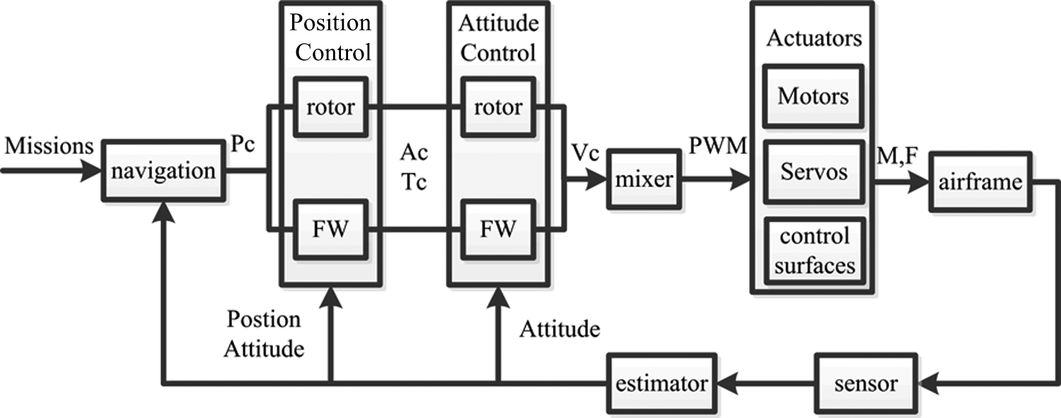
The control structure. Pc , A c, and Tc represent the position, attitude, and thrust command, respectively. Vc represents the virtual control command. FW represents the fixed-wing mode. PWM: pulse-width modulation.
The position control loop takes the global position command and the current position as inputs and outputs the attitude and thrust command vector to the attitude control loop. In the fixed-wing mode, the position control loop is composed of the longitude control and the lateral control. The lateral control adopts the L1 navigation logic, 26 which combines the current position of UAV and a reference point on the flight path at a distance L1 to generate the lateral acceleration command acmd

where η is the angle between the direction of airspeed Va and the direction of the current position pointing to the reference point. Then the yaw command ψc could be calculated by the position command and the current position, the roll command ϕc could be calculated by acmd 27 in coordinated turn condition as follows

The longitude control adopts the total energy control system method consisting of the inner and outer loops. The outer loop adopts a PD controller for the airspeed and altitude channels, respectively. The outputs of the outer loop together with the airspeed derivative are first converted to energy rates, and then the inner loop adopts PI controller with energy rates generating the pitching command θc and thrust command Frotor.
In rotor mode, the main procedures of the position control are presented, readers may refer to the work of Mellinger D and Kumar 28 for details of the entire algorithm: first, the position tracking error e along Z axis of the geodetic frame (GF) generates the thrust FZ along Z direction in GF

where zc is the position tracking command along Z axis of GF, kp and kd are the control parameters, m is the mass of the UAV, and g is the gravity acceleration. The thrust command Frotor could be calculated by FZ through a coordinate transformation; then, the rotation matrix command from the body frame (BF) to GF, Rc could be calculated as follows

where

where V represents the vee map which takes elements of so(3) to ℝ3.
The attitude loop in all flight modes adopts two control loops 25 : an angular loop and an angular rate loop. The angular loop, which is relative to the geodetic coordinate system, uses the P controller to achieve the angular rate command for every channel. Through a coordinate system transformation, the angular rate commands in BF are input to the angular rate loop, which uses the PID controller to generate virtual control commands as shown in the following equation

where Mx, My, and Mz are the virtual control commands for roll, pitch, and yaw channels, respectively; er is the angular rate error vector; and kMp, kMd, and kMi are controller parameters. Mx, My, Mz, and Frotor together constitute the virtual control commands. The virtual control commands are the weighted sum of the outputs of the rotor and fixed-wing modes. The mixer used as the control allocation maps
The control allocation
The inputs of the mixer are the virtual control commands of four channels
Because the virtual command

where Ur is the virtual commands of the rotor mode, Uf is the virtual commands of the rotor mode, and weight_r is the weight of Ur. In the rotor mode, weight_r is 1, and in the fixed-wing mode, weight_r is 0. During the P1 stage of the conversion mode, because the direction of the rotor thrust varies during the conversion mode, the induced airflow can have a changing influence on the wings. Moreover, the airspeed of the UAV in stage P1 is low, and the efficiency of the aerodynamics is low; therefore, the force and moment produced by the control surfaces are comparatively small, changing, and difficult to evaluate accurately. weight_r is 1 during stage P2 of the conversion mode because the rotors all stop, and when the airspeed is above the switching speed, weight_r is 0. In reconversion mode, all the rotors stop, the weight_r is 0, and the airspeed remains large; therefore, Uf will work until the airspeed is reduced below the switching speed. The weights are listed in Table 2.
The weights in different modes.

UAVs: unmanned aerial vehicles.
The force analysis for establishing the mapping relationship from the virtual control command U to the actuators is shown in Figure 7.

The body frame and geodetic frame.
The two reference frames given in Figure 7 are BF

where the gyroscopic moments Mgyro is created by the gyroscopic effect of the motors and rotors, the reaction torque Mrotate is exerted on the hub of each rotor during rotation due to the drag of rotors, Mthrust is created by the thrusts of the rotors, and Maero is created by the drag/lift forces of the wings, although this is neglecting when weight_r is 1, Mgyro is assumed to be insignificant compared with Mthrust and Mrotate considering that the moment of inertia of the motor is small and the tilting angular rate is low; therefore, the expressions of Mrotate and Mthrust are given as

where s and c are short for sin and cos, respectively, kq is the rotor moment coefficient, and Ω1, Ω2, and Ω3 are the speeds of rotors 1, 2, and 3, respectively.

where
F is the total external force along the Z axis in the BF based on neglecting the force generated by the aerodynamics of the airframe. The total force can be expressed as

where Fg is the gravity and Frotor are the sum of thrusts of rotors. The expressions for these values are given as


By combining formulas (9), (10), and (12), U is expressed as

where

In the first allocation, the number of actuators

where

where
Experimental results
A full-mode flight experiment including VTOL, conversion, cruising, and reconversion was implemented in the MISSION control mode with a wind speed of 2–3 ms−1. The duration of the flight is less than 5 min, and the flight trajectory is preprogrammed in QGroundControl, as shown in Figure 8. The orange line is the predetermined route, and the red lines are the actual flight trajectory. The flight trajectory and the route coincide very well. The tilt-rotor UAV takes off toward navigation point 1. Point 2, which is used as a function point, shares the same physical position as point 1 for adjusting the direction and triggering the conversion command. The tilt-rotor UAV flies twice along a length of 500 m2, and the altitude command during cruising in the fixed-wing mode is 35 m. After point 35, the tilt-rotor UAV begins to descend. Point 38 shares a physical position with point 37 for triggering the reconversion command. The tilt-rotor UAV switches to the rotor mode and lands at point L. To verify the stability and tracking performance, during cruising, the trajectory adds additional navigation points, such as points 20, 26, 30, and 33, to trigger the pitch excitations making the tilt-rotor UAV change in the pitch channel. The three-dimensional flight trajectory shown in Figure 9 is transformed from GPS records to the local frame, whose origin is the takeoff point.

Flight trajectory and navigation points displayed in QGroundControl, the red line is actual trajectory, the orange is the designed trajectory.

3D flight trajectory during the whole flight test.
The full-mode flight mode experimental results are shown in Figure 10. Because no sensors measure the deflection of the control surface, the normalized control inputs, which follow a linear relationship with the deflections of the corresponding control surfaces, are used to represent the deflection angles. Similarly, the tilting inputs and the PWMs of the rotors are used to represent the tilting angle of the servo motors and the speed of the rotors, respectively. The fixed-wing mode is active from 26.04 to 245 s. In the fixed-wing mode, ϕ could track the command perfectly. There is a delay in the yaw channel tracking the command. The excitations in the pitch channel are implemented by changing the control input of the elevator. The changing magnitude of the control input is 0.2 based on the current quantity. θ and the altitude oscillate with the excitations. The tilt-rotor UAV could regain trim attitude after this oscillation. θ can track the command, and the response speed is fast; however, there is an error that may be due to the use of improper controller parameters. The airspeed could ensure an airspeed command of 18 ms−1 when there was no excitation.

Flight results in full-mode flight. s1 and s2 represent the servo motors 1 and 2, respectively; r1, r2, and r3 represent rotors 1, 2, and 3, respectively.
The details of the rotor and conversion flight mode are shown in Figure 11. The rotor mode is from 5.7 to 21.55 s, and the conversion mode is from 21.55 to 26.04 s. In rotor mode, ϕ and θ could track the command well; however, there was a deviation in the yaw channel that is caused by the effect of current on the compass. Although the Pixhawk was placed as far as possible away from the battery and wires, the effect on the compass cannot be eliminated. From 19.82 to 21.55 s, the tilt-rotor UAV adjusted its heading severely via differential control, the yaw response was fast, and there was no overshoot. In the conversion mode from 21.55 to 25.4 s, the roll channel remained stable, the yaw channel was not controlled, and ϕ did not track the command at all. The pitch command was gradually downward to accelerate, and θ could track the command in the first 2 s. Then, θ gradually increased without tracking the command. This phenomenon is caused by the error in the estimation of the tilting angle. Because the tilting angle is computed via the off-line calibration of the tilting input and is not achieved by the direct measurement of a sensor, the error between the actual tilting angle and the estimated angle is small when the tilting angle is small and gradually increases with increasing tilting angle. The increasing error causes the control allocation to be inaccurate, resulting in the pitch deviation. When the deviation increases, the PWM of rotor 3 increases, and the PWMs of rotors 1 and 2 decrease; in addition, θ no longer increases. Before switching to the fixed-wing mode at 25.6 s, all the rotors first stop 0.2 s prior to make the transition smooth. Once in stage P2, the control surfaces begin to take effect at 25.4 s. The switching airspeed of 12 ms−1 is below the stall speed; from 26.04 to 28 s, the tilt-rotor UAV applies a diving acceleration with large rotor speeds. The airspeed increases to 17 ms−1 at 28 s. In stage P1, the attitude is stable, and in stage P2, the attitude generates oscillations in the pitch and roll channels. The reason for this phenomenon is the switching from the rotor position control to the fixed-wing position control. However, the two channels can almost track the respective command in the conversion mode and converge to a steady state in the fixed-wing mode. The yaw channel generates a maximum deviation of 58° and can converge to the command in the fixed-wing mode. The altitude remains unchanged in the conversion mode and decreases by 5 m to accelerate in the fixed-wing mode.

Flight results in rotor and conversion mode. s1 and s2 represent the servo motors 1 and 2, respectively; r1, r2, and r3 represent rotors 1, 2, and 3, respectively.
The details of the reconversion and rotor flight mode are shown in Figure 12. The reconversion mode is from 243.1 to 243.8 s. Because the controller parameters of the fixed-wing position control and rotor position control are different, a sudden switching between two POSCTLs leads to the commands of ϕ, θ, and ψ suffering from large variations. This causes a 30° upward shift and subsequent adjustment in the pitch channel in order to track the command and slight variations in the roll and yaw channels. Although θ exhibits a large variation, the tilt-rotor UAV could restore stability within 3 s from 244 to 247 s. The altitude remained approximately constant during the reconversion mode. The control surfaces stopped having an effect until the airspeed was below the switching airspeed of 12 ms−1 at 246 s, which helped stabilize θ. The rotors stopped 0.3 s prior to the reconversion mode and gradually increased after the reconversion mode to make the transition smooth. In rotor mode, there were significant excursions from the stable state in the roll channel from 254 to 257 s, which may have been caused by gusts. Although the amplitude of the variation is larger than 100°, the tilt-rotor UAV was able to restore stability.

Flight results in rotor and reconversion mode. s1 and s2 represent the servo motors 1 and 2, respectively; r1, r2, and r3 represent rotors 1, 2, and 3, respectively.
The results of the flight experiment show that, even if there is a 50° amplitude of variation in the pitch channel during the conversion mode, a series of pitching oscillations in the fixed-wing mode, a 30° amplitude of the pitch variation in the reconversion mode, and a series of roll oscillations with a magnitude of 100° in rotor mode, the tilt-rotor UAV could restore stability. This validates the performance of the mixer and the feasibility of the flight strategy. Because the reconversion mode can be achieved without deceleration, the approach distance and time are reduced. However, there is a phenomenon that need be addressed, when the tilt-rotor UAV switches between the rotor mode and the fixed-wing mode, the attitude generates a fluctuation, which may rise a difficulty in some applications that need keep continuous and stable attitude such as aerial photography. Snapshots of the flight test are presented in Figure 13.

Flight snapshots of the flight.
Conclusion and future work
Aiming at portability and tasks characterized by constrained small scope areas, a tricopter configuration tilt-rotor UAV prototype is developed. The tilt-rotor UAV adopts differential tilting of the front rotors, therein reducing the number of actuators compared to other tricopter configuration tilt-rotor UAVs such as TURAC and FireFLY6. Compared to Panther and mini Panther, the proposed tilt-rotor UAV is more compact and man-portability. The controller architecture of the autonomous flight is presented. Without wind tunnel modeling a precise dynamic model, a feasible full-mode flight strategy is designed according to the performance and features of the tilt-rotor UAV, which reduce the cost. Moreover, a control allocation method is proposed to solve the problem that the system is not input-affine and that the number of actuators is different from the number of control channels. The successful autonomous full-mode flight test shows that, regardless of the flight mode, even if there are large deviations of the attitude from the equilibrium state, the tilt-rotor UAV can restore stability and demonstrates that the flight strategy is feasible and the control allocation is effective. Future work will enhance electromagnetic isolation to reduce the effect on the compass, optimize the switching process between rotor and fixed-wing position control to reduce oscillations, install a sensor for the tilting angle, and further increase the flight duration by adopting carbon composite materials to reduce weight.
Footnotes
Declaration of conflicting interests
The author(s) declared no potential conflicts of interest with respect to the research, authorship, and/or publication of this article.
Funding
The author(s) received no financial support for the research, authorship, and/or publication of this article.