
Abstract
A key research subject in the area of unmanned aerial vehicles (UAVs) is how to make them autonomous. Towards this goal, the most vital step is stabilizing the attitude of the vehicles. This paper presents the design of an autonomous control system for a hybrid UAV to enable it to carry out a stable hovering mission under external wind disturbances. The hovering capability of the hybrid UAV under windy conditions is analysed with computational fluid dynamics (CFD) and a control law is designed to stabilize the craft in the hovering position. The proposed hovering controller is verified with simulations and experiments. Finally, the flight control system is installed in a small prototype and a full transition flight test, including vertical take-off, transition from vertical flight to cruise, cruise, transition cruise to vertical mode and hover landing, is successfully accomplished.
Introduction
Today, unmanned aircraft systems are able to operate in a highly mechanized manner and perform intelligent navigation both indoors and out, even under conditions of weather disturbances. However, depending on the demands of the application, mission flights can be complex. For instance, large-area scanning of a specific target while simultaneously providing on-site assistance will need the aircraft to have a multi operational nature. Design of aerial vehicles has long sought to develop vertical take-off and landing (VTOL) aircraft that are capable of performing an extended operational flight Such aircraft also need to hover at a particular position at a higher altitude for longer than is currently possible. Further, it is desirable for such vehicles to be weightless, transportable and mission-ready at short notice. On this background, a special UAV design is implemented in this paper. The vehicle is designed to perform a vertical take-off, manoeuvre during flight mode and perform a conversion from rotor hover mode to fixed-wing longitudinal flight. The hovering capability of this hybrid UAV under windy conditions is analysed with computational fluid dynamics and a control law is designed to stabilize the aircraft in the hovering position.
Recent advancements in building hybrid air vehicles to meet current needs have facilitated UAV configurations such as Tilt Rotor, Tilt Wing and Tilt Body. In [1], a Tilting Tri-Rotor unmanned aerial vehicle is developed and the control law is designed based on the nonlinear dynamics of the derived model. The controller is designed using the characteristics of the extracted model. These Tilt-Rotor configurations are found to be unstable at low speeds.
A Tilt Rotor UAV tilts the rotors during the course of flight transfer from quadcopter mode to cruise mode, while keeping the wing surface horizontal to the ground. However, during hover and VTOL, these rotors impose a download on the upper surface of the wing. This decreases the payload capacity of the vehicle [2, 3]. The download is about 9% of the thrust [4]. But while the vehicle approaches the ground during landing, high pressure below the wings and fuselage causes an upload, as the wakes of all the rotors meet underneath the fuselage and turn upwards. To minimize these effects, the wing is kept vertical during take-off and landing, and kept tilted during the cruise mode.
The aerodynamic design of an electric-powered quad tilt-wing UAV (SUAVI) is presented in [5]. The design and prototyping of a flight control system capable of vertical take-off and landing (VTOL) like a helicopter and long-duration horizontal flight like an airplane is implemented. This UAV is configured with the wing surface perpendicular to the ground during VTOL, with four rotors mounted on the wing, so that the wing and the rotors tilt simultaneously during transition from VTOL to cruise mode.
A dynamic model of a quad-rotor aerial vehicle (SUAVI) equipped with a tilt-wing mechanism is presented in [6]. A dynamic model is derived for vertical and horizontal flight modes using a Newton-Euler formulation. An LQR controller for the vertical flight mode is developed. In [7], the design of a robust hovering controller for a quad tilt-wing UAV to hover at a desired position is presented. Wind and aerodynamic disturbances are modelled using the Dryden model. In order to increase the robustness of the system, a disturbance observer is introduced to estimate the unknown disturbances acting on the system.
In [8], the authors propose a novel hovering-control strategy for a tail-sitter VTOL UAV that increases stability against disturbance. An inverted pendulum-model-based tilt-twist angle control with PID controller is implemented. For large error angles around the Z-axis, this controller offers better stability in comparison with the quaternion feedback controller. In [9], quadrotor control is divided into subsystems, namely, attitude control and altitude control. Attitude control is accomplished by a PID controller and altitude control by back-stepping-based dynamic surface control (DSC). The effectiveness of the controllers are validated by simulations and experiments.
A control system of a quadrotor based on a complementary filter to handle attitude estimation and PID controllers to handle the attitude stabilization is detailed in [10]. Through flight experiments, the PID control system is tested and the system efficiency validated. In [11], the flight performance of the UAV is improved with the control structure (PI- D) - PI on the main path and D on the feedback path, in comparison with (PID) - PID on the main path and (I- PD) - I on the main path and PD on the feedback path.
In [12] an analytical optimization method is employed to tune a conventional PID controller for stabilization of the quadrotor. The time domain performance of the designed control structure is evaluated with an IAE objective function and the applied control strategy is validated using simulation.
In [13] the authors find that the asterisk-type UAV has good attitude control capability when compared to the cross-type. A dynamic model of quadcopter is developed and a proportional and derivative controller for altitude, roll, pitch and yaw is simulated using MATLAB Simulink® [14]. The dynamics of the rotor is discussed using momentum theory and blade element theory. The Euler-Lagrange method is used to derive the equations of motion of a quadcopter.
From study, it is inferred that, during hover, models with vertical wing configuration experience a drift under windy conditions. For the increased wing area and wind speed the disturbance for hovering also increases, creating more drift and unstable hovering. Though UAVs have GPS based attitude control, they have to expend more power for hovering in light wind condition. Under moderate and heavy winds the model gets drifted along the wind direction during vertical take-off/landing and hovering. Hence, in the present work a novel approach to get away with wind-based disturbances during hover is attempted.
A special case of wind disturbance during hovering with vertical wing configuration is considered for the present study. A small-scale tilt vehicle with four rotors and a wing is developed in the laboratory. The vehicle is developed with the ability to rotate the airframe from VTOL mode to longitudinal flying mode and vice versa. The effect of wind during hovering is analysed using CFD and it is addressed by inclusion of a yaw control loop in the flight control system. The aim of the work is to sense the wind speed in the direction of current heading during hovering, so as to avoid the impact of wind by slewing the frame about the yaw axis. This will make the heading of the UAV align in the lesser drag position using the yaw command. By this simple impact elimination, hovering performance under worst wind conditions is enhanced and power consumption is reduced.
This paper is structured as follows. In Section 2, the UAV platform is discussed. In Section 3, the vertical and horizontal flight dynamics is presented. In Section 4, the effect of wind on the vehicle is studied using CFD and its performance during hovering is discussed. In Section 5, the problem is addressed by implementing an enhanced hovering control loop in the flight controller. In Section 6, simulation and hardware results are presented. Finally, conclusions are drawn in Section 7.
UAV Platform
Structure
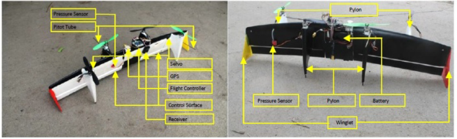
The structure of the UAV under study is shown in Figure 1. The vehicle structure has a wing with a pair of winglets, one at each wing tip, and two pylons attached at the appropriate place on either side of the wing surface. A symmetrical airfoil wing of span 1.5m and 0.2m chord is used. Winglets reduce the vortex and the pylons serve as vertical stabilizers during horizontal flight. The pylons also house the brushless DC motor and act as landing gear for the UAV. The system uses two pairs of 200-Watt brushless DC motors that rotate in opposite directions. 10X4.5 inch propellers are connected to clockwise motors and 10X4.5R inch reverse propellers are connected to anti-clockwise motors. Two deflectable control surfaces (elevons), hinged at the trailing edge of the wing, combine the functions of the elevator and aileron.
Electronic System
The electronic system integration is depicted in Figure 2. The flight controller board is placed at the CoG (centre of gravity) of the vehicle. It comprises an ATMega 2560 microcontroller for processing the sensor information and for the generation of PWM command signals. A MPU6050 three-axis gyro/accel unit measures the attitude, three-axis angular velocity and translational acceleration. A HMC5883L three-axis digital magnetometer reads the heading, an MS5611-01BA01 high-precision altimeter reads the altitude; an MPXV7002DP airspeed sensor with 2.5% of full scale output (4.5V) error is employed for the wind-speed measurement. A NEO–6, UBLOX GPS with horizontal position accuracy of 2.5m and velocity accuracy of 0.1m/s is employed to obtain the position of the vehicle and the velocity with respect to ground.
Communication between UAV and the GCS (Ground Control Station) is established by an XBee Pro Modem fixed on the GCS and on the UAV. The manual control of the UAV is exercised by a Futaba 8 FG radio-control transmitter and R6208SB Receiver.
A three-cell 12.6V – 5000mah lithium polymer battery is the power source. Speed of the motor is controlled by a 20A ESC (Electronic Speed Controller). The servos that are attached to the control surfaces enable their deflection. The ESCs and servos are driven by the PWM signals that are generated by the flight controller, based on the current state of the UAV measured by sensors and GPS. The total mass of the UAV is 1.5 kg.

UAV Schematic
The VTOL mode of the vehicle is detailed in Figure 3(a) and the horizontal mode in Figure 3(b). During take-off, landing and hover, the system functions like a quadcopter, with the wing surface perpendicular to the ground. In cruise mode, the vehicle works like a flying wing with all the rotors providing thrust.
In VTOL mode, the propellers are kept pointing up at the sky. The total thrust produced by the four rotors controls the hovering altitude, while the elevons are kept at zero deflection. In this case, the roll angle (φ) is controlled applying differential thrust between the rotor pairs M1M4 and M2M3. The pitch angle (θ) is controlled by applying differential thrust between the rotor pairs M1M2 and M3M4. The yaw angle (ψ) is controlled by applying differential thrust between the rotor pairs M1M3 and M2M4. In horizontal flight mode, the rotor thrust aids the forward movement. The pitch and yaw angles are controlled by elevator and aileron.

Electronic System
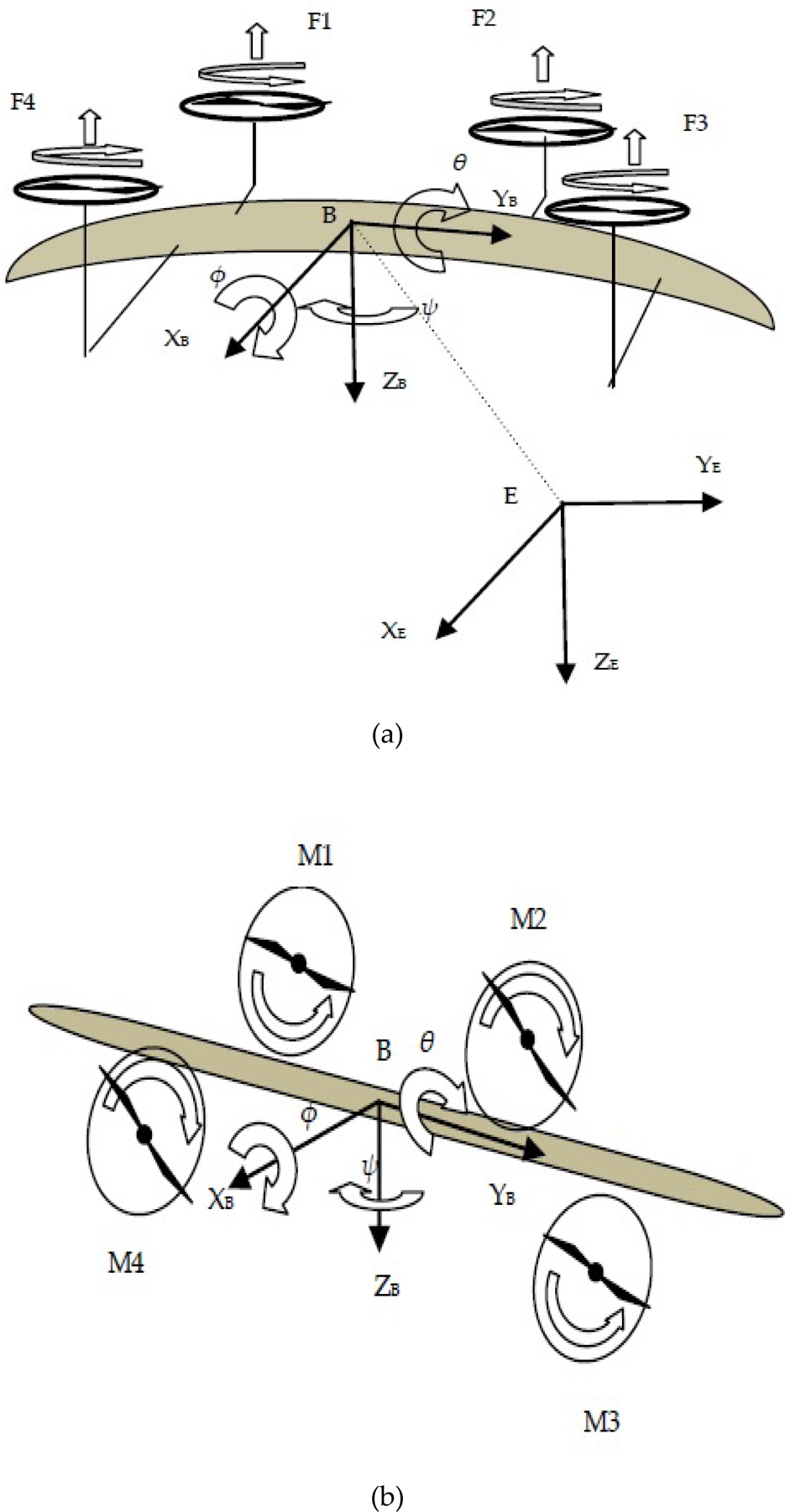
(a) VTOL and hover flight – wing surface perpendicular to the ground. (b) Horizontal flight – wing surface parallel to the ground.
In vertical flight mode, the mechanical structure of the vehicle is very similar to a quad-rotor vehicle. The two reference frames shown in Figure 3(a) are the body frame (X B , Y B , Z B ) and the earth-fixed inertial frame (X E , Y E , Z E ).
The position and linear velocity of the vehicle in the earth frame are described as:


The attitude and angular velocity of the vehicle in earth frame are given as:
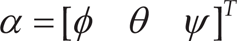
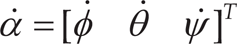
where φ, θ, ψ are roll, pitch and yaw angles, respectively.

Lever arm distances from body XB and YB axis
From Figure 4 the control inputs U1, U2, U3 and U4 for altitude, roll, pitch and yaw are found as:
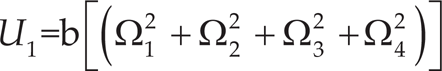


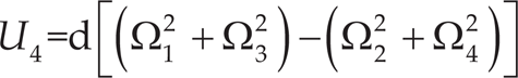
where Ωi=1, 2, 3, 4 are the propeller speed and band dare the thrust and drag moment constants, respectively.
The translational and rotational parameters [8] are found as:
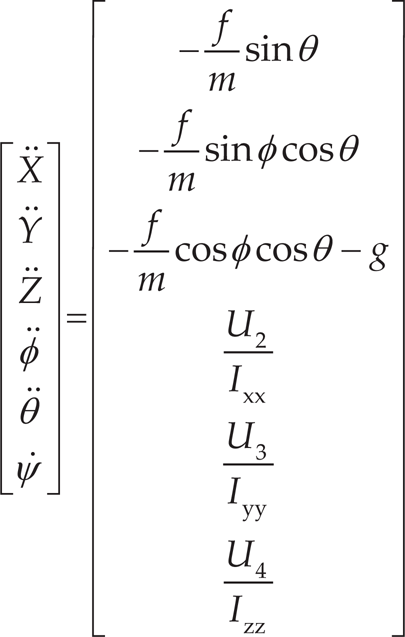
where f is the total thrust force, which is U1.
In horizontal flight mode, the mechanical structure of the aerial vehicle is similar to the airframe of a flying wing airplane. The relative wind acting on the airplane produces an aerodynamic force. This force can be resolved in to two components: lift, which acts perpendicularly to the direction of relative motion, and drag, which acts in the opposite direction to the relative motion. The lift and drag forces are:

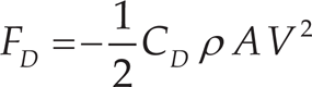
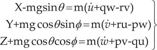
where CL and CD are lift and drag coefficients. The total force F Airplane acting on the centre of gravity of the vehicle is the sum of the forces F rot created by the rotors; the gravity is F cg ; the lift and drag forces generated by the wing are F wing . The force equations in X, Y, Z directions are:
The moment equations are:

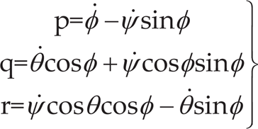
The vehicle-body fixed angular velocities as a function of Euler angles and Euler rates are:
The 3D continuity and momentum equations with appropriate boundary conditions are solved under steady, incompressible conditions using the commercial CFD software, ANSYS FluentTM. The convective flux coefficients are derived by a second-order upwind scheme. The velocity and pressure fields are coupled using the SIMPLE algorithm [15]. All the numerical tests are performed with convergence threshold residuals for the continuity and momentum equations equal to 10−5.
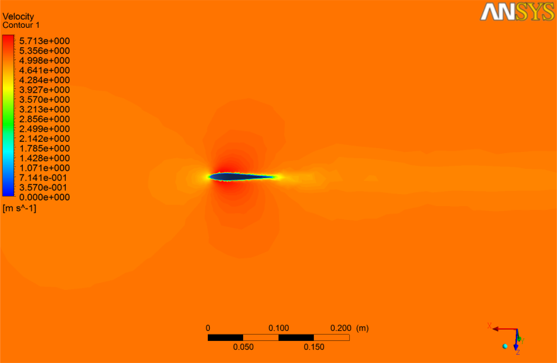
A three-dimensional tetrahedral-type mesh was created for the geometry of the problem. Numerical simulations are carried out for three different air speeds, 5, 10 and 20 m/s, with two wing-position configurations of flow parallel (zero angle of attack) and perpendicular (90° angle of attack) to the wing surface. When the wing is parallel to the flow direction, it is observed that the flow is smooth and not very much separated in the flow direction, as shown in Figure 5 and Figure 6. However, two recirculation regions are identified behind the winglet and behind the pylon on the downstream side, as shown in Figure 7. Due to this flow behaviour, the drag coefficient for this case ranges from 0.04 to 0.12, as shown in Figure 11. But the download reduces the payload capacity and during landing, there is high pressure below the wings and fuselage, which causes an upload when the wing surface is parallel to the ground. To minimize these effects, the wing surface is made vertical during take-off and landing.
When the wing surface is vertical to the ground and in normal position in relation to the flow direction, the flow is seen to be separated in the downstream, and a recirculation zone is formed behind the wing. The flow phenomenon is similar to the flow over a vertical flat plate as the geometry acts as an obstruction to the fluid flow. As a result, back-pressure is created in the downstream and flow is separated as in Figures 8–10.
Vertex-shedding is found along the wingspan. The patterns formed in the different slices other than the pylon cut sections, are similar to those of Von Korman vortex sheets formed behind a circular cylinder at higher Reynolds numbers, as shown in Figure 8. Along the cut sections of the pylons, the vortices are shed initially like a single Von Korman vortex sheet, then split into two sheets and finally diffused in the main flow upstream, as can be clearly seen in Figure 9(a). These complex reversal flow patterns, as shown in Figure 9 and Figure 10, create back-pressure on the wing surface and increase the drag force significantly. The drag force coefficient for the vertical wing case is 0.9, as shown in Figure 12.
Velocity contours on the symmetry plane when the wing is parallel to the flow direction

Streamlines at different planes over the horizontal wing surface. (a) Plane parallel to wing surface. (b) Symmetry plane.

Zoomed view of velocity vector for the horizontal wing position to flow direction

Velocity contours on symmetry plane when the wing is perpendicular to the flow direction
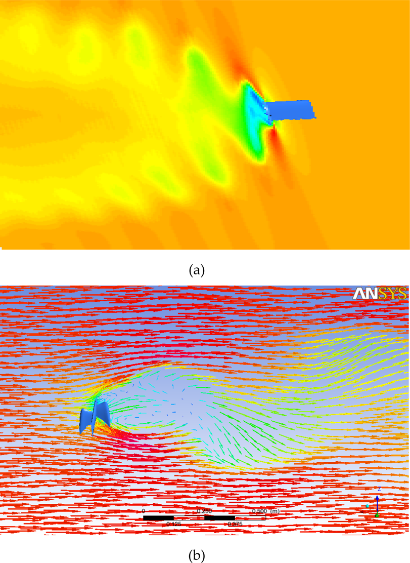
(a) Velocity contours on the symmetry plane for the perpendicular wing to the flow direction. (b) Velocity vectors on the symmetry plane for the perpendicular wing to the flow direction.

Velocity vectors for the perpendicular wing to the flow direction. (a) On the plane parallel to the top wall of exterior domain. (b) On the pylon plane.

Variations of coefficients of lift and drag for the wing surface positioned parallel to flow direction

Variations of coefficients of lift and drag for the wing surface positioned perpendicular to flow direction
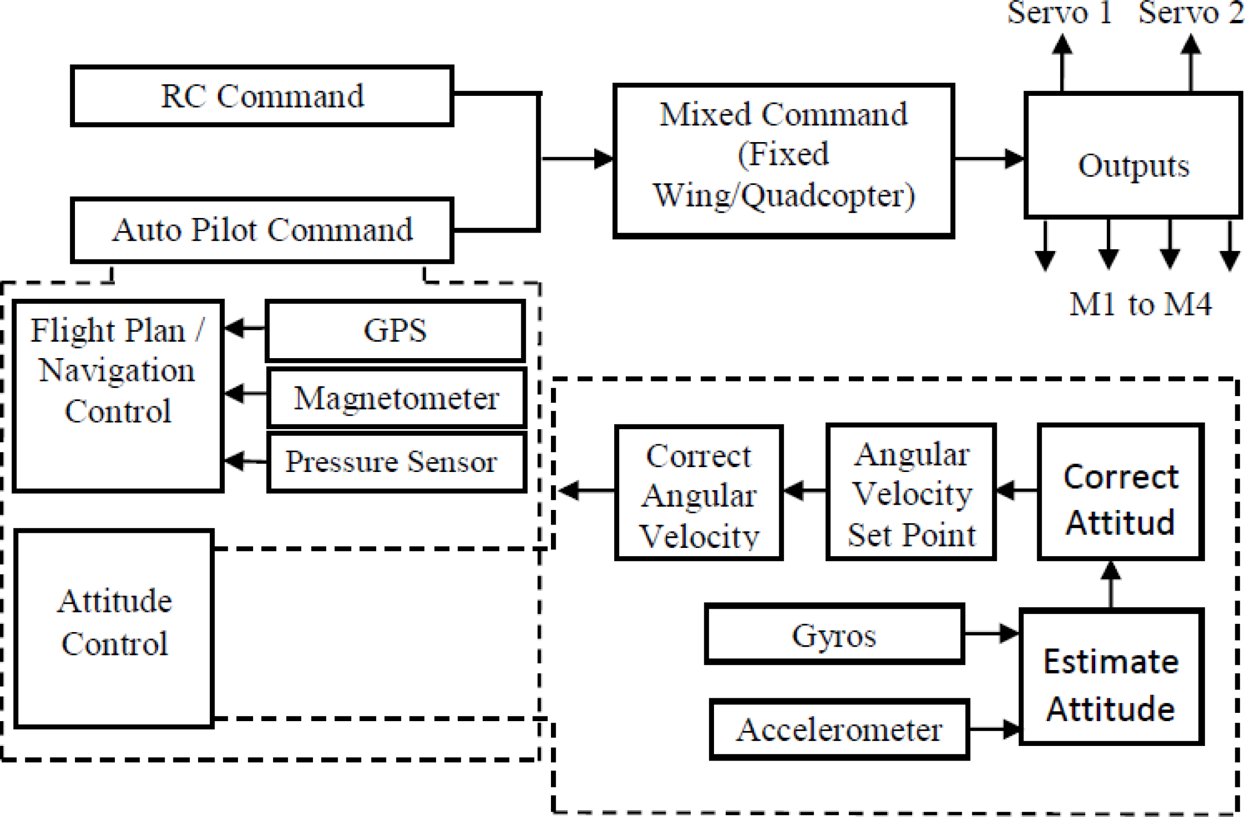
The UAV under study is capable of performing VTOL and horizontal flight. The UAV has two flight modes, namely quadcopter and fixed wing. A block diagram of the flight controller is depicted in Figure 13 and the modified attitude-control system is shown in Figure 14. The autopilot system is employed with sensors for state determination. It deploys on-board processors for state estimation and control purposes. The reduction of the wind disturbance while hovering using the proposed enhanced flight controller is detailed below.
Overview of the System
The RC transmitter releases control signals for throttle, roll, pitch and yaw. The signals are received by the RC receiver, which passes them on to the mixer. The data are sent as PWM signals. The ON time of the pulse, which is about 1ms to 2ms, defines the amount of control. The throttle, roll, pitch and yaw are the input data received by the mixer. The mixer splits the received R/C signals and produces the required control signals.
In combination with suitable on-board algorithms, the UAV uses sensors to estimate translational states and rotational states. The transmitter has a flap switch for manual and autopilot control and for quadcopter and horizontal flight mode, respectively.
Auto Pilot
The UAV autopilot system has two principle functions: state estimation and control inputs generation. Control inputs are generated based on the reference paths and the current states. State is estimated using the micro-inertial guidance system with gyro, acceleration, pressure, and magnetic sensors. The sensor readings coupled with the GPS information are fed to a filter to estimate the current states for control. Based on the control formulations, autopilots can be classified as PID, fuzzy, neural network and robust autopilots [16]. With MEMS technology it is possible to use tiny and weightless sensors on mini and micro UAVs.
Flight controller
GPS
GPS provides the absolute positions and ground velocities. Below are the state observations.
P north : North position; P east : East position; h MSL : Height above MSL; V north : North inertial velocity; V e : East inertial velocity; V down : Downward inertial velocity.
The horizontal component of the GPS velocity vector is also expressed as a GPS ground speed (V Hor,GPS ) and course heading (X GPS ),

A static pressure sensor is employed to measure the barometric height by comparing the current pressure with the pressure at some reference height. If the static pressure at the launch point is P s,launch , as recorded by the UAV, and P s the current static pressure, then the height above the launch point is estimated from the barometric pressure sensor as:
where ε h is the sensing error.
Accelerometers measure specific force,

Gyros
To estimate the body attitude, an inertial measurement unit (IMU)-based attitude estimator makes use of three-axis gyros and accelerometers. A gyroscope measures the angular rate about a specific axis. The angular rates in the body axes X B , Y B and Z B are ω x , ω y and ω z , respectively. The body rates and Euler angle rates are related as below.

The body yaw angle (ψ) is estimated using a magnetometer. The magnetic declination (ψ mag ), which is the difference in bearing between true North and magnetic North, is determined. The 3-D magnetometer provides Mx, My, Mz of magnetic North in body coordinates. The magnetometer-based estimate of yaw equation is given as:

The orientation of the UAV is denoted by Euler angles of yaw, pitch, and roll. These Euler angles define the transformation from the inertial earth frame to the UAV body frame. The transformation from the earth X E − Y E − Z E coordinate frame to the body X B − Y B − Z B coordinate frame is written as a cascade of the three single-axis rotations.

where c and s are cosine and sine.

Modified attitude control system
Proposed UAV
The study vehicle developed is shown in Figure 15. Wind speed is read by means of pitot tubes fixed one on either side of the wing surface. The pitot tubes are connected to the pressure sensors in such a way that the air stream entering the tube is not affected by the prop wash. Thus the vehicle speed relative to wind, which is the axial airspeed of the UAV, is measured. The total pressure measured through the pitot tube, P T , is the sum of the static pressure P s and the dynamic pressure P dyn . The wind speed measured by the airspeed sensor (V Airspeed ) is given as:
The schematic of the proposed hover controller is depicted in Figure 16. In GPS position hold, the flight controller sends PWM commands to the motors to maintain the position irrespective of the wind condition. The drag experienced by the vehicle during hover can be calculated using GPS-measured velocity and wind speed. In the absence of the proposed controller, for low and moderate wind speeds (1m/s to 3m/s) the vehicle draws more power from the battery for stable hovering against the drag created by the wind. Here, the GPS velocity in relation to the ground is minimal or zero, while the velocity measured by the airspeed sensor (V Airspeed ) is considerable. With strong wind (speed > 3m/s) the vehicle draws more power from the source for position hold and will tend to drift with the wind. Here, the velocity output of the GPS and airspeed sensor will be high. For low and medium wind speed, the GPS velocity output is nil or minimal; hence, only wind speed (V Airspeed ) is considered in the enhanced hover control.
The enhanced hover controller utilizes the wind speed measured by the airspeed sensor (V Airspeed ) and the current orientation of the plane from the magnetometer. When V Airspeed is greater than the threshold velocity, the flight controller calculates the desired heading and initiates a yaw command. For the present case, threshold velocity (V th ) is fixed as 1m/s. The yaw command provides required PWM pulses to the motors to create a yaw movement in small increments of 5° from the current position, until the airspeed sensor reading is below the threshold value. Now the UAV is oriented to a position of less drag and the power consumption is also brought down. When the airspeed is less than the threshold, the vehicle hovers with GPS-based attitude stabilization.

Flow diagram of enhanced hover control
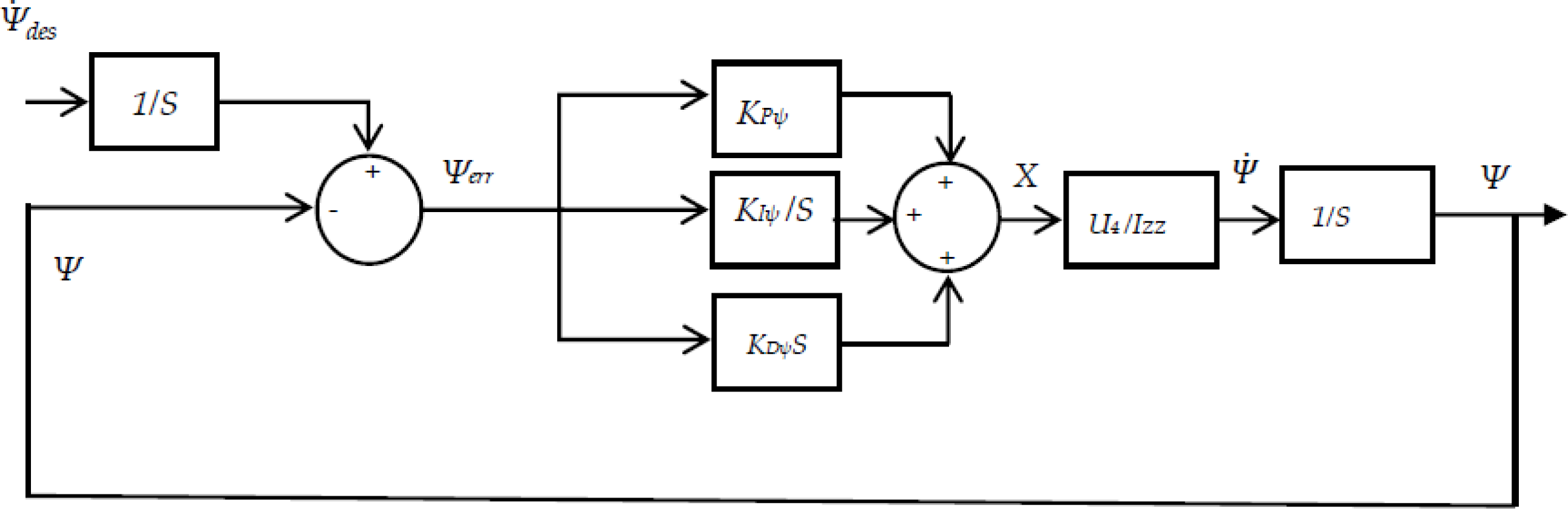
The control algorithm uses PID controllers for roll (φ), pitch (θ), yaw (ψ) and altitude (Z) controls to achieve attitude stabilisation during hover. In hover control, the incremental yaw angle ψdes is set as 5°, for a wind speed greater than the threshold. The yaw control loop is depicted in Figure 17.
The controlled variable X is the ON time of ESC's PWM pulse, which controls the speed of the motors. The ON time of the PWM pulse is varied between 1ms and 2ms. The error between the task and the process output is denoted as ψerr. KPψ is the proportional coefficient, KIψ is the integral coefficient, and the derivative coefficient is denoted as KDψ.

The difference in the ON time of the PWM pulse between the motor pairs depends on the error angle ψerr. Izz, the moment of inertia about the Z-axis, is a factor for the yaw control U4, as related in Eqs. (8) and (9).
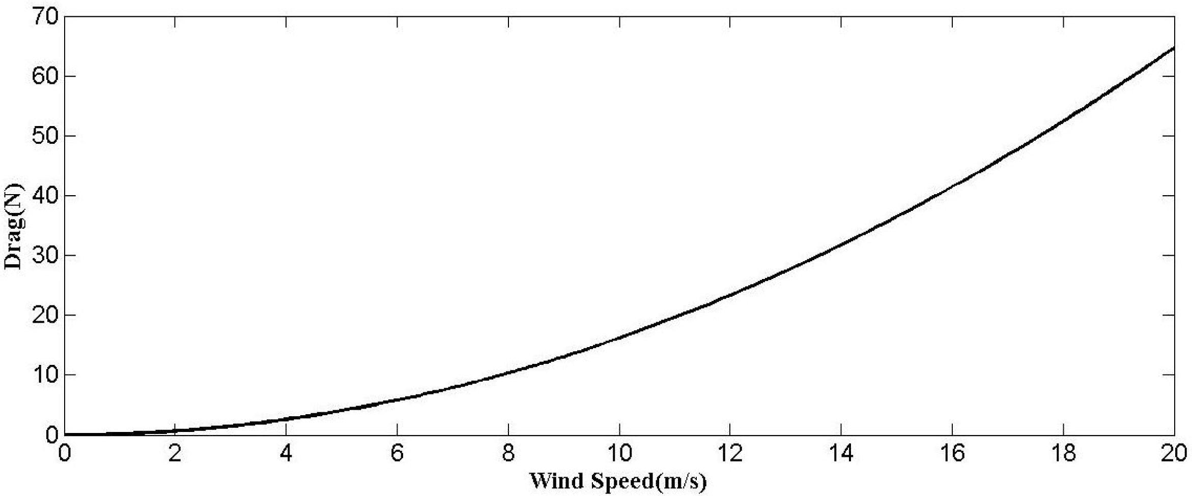
During VTOL, the primary forces that act on the quadcopter are the collective thrust and the weight, which act against each other. The altitude of the vehicle is the factor of the collective thrust. While hovering, the resultant force on the vehicle along the X B -, Y B -, and Z B -axes of the body frame is zero. For the vehicle under study, the wing surface is perpendicular to the ground during hover. The drag coefficient of the vehicle during hover for wind along the X B -axis is found to be 0.9. The drag forces experienced by the model are computed and plotted against wind velocities for the obtained drag co-efficient, as shown in Figure 18. Where the velocity of the wind is varied from 0 to 20 m/s, it is observed that the drag experienced by the vehicle decreases when wind speed decreases.
Yaw control loop
Drag force induced for different wind velocities (wind along XB-axis)
To investigate the stability of the controller, a simulation model is created as shown in Figure 19. This model contains separate PID controllers as in Eq. (23) for attitude (each for roll, pitch and yaw) and altitude control. The controller inputs are the desired roll, pitch, and yaw angles, altitude and the current values sensed by the sensors. Based on the difference between the desired and actual values, the controllers generate PWM pulses for ESCs with suitable ON time. These pulses change the speed of the motors. The calculated speed is deduced to provide the control inputs U 1 , U 2 , U 3 , U 4 by the control input block using Eqs. (5), (6), (7) and (8). The control inputs are converted in to roll, pitch, yaw and altitude by the UAV dynamics block using equation (9). For hover, the desired roll, pitch and yaw inputs are zero for constant altitude. However, if the wind speed is greater than Vth, the desired yaw input is taken as 5°. During normal hover, the roll, pitch and the yaw output would be zero with unvarying altitude. However, the vehicle is subjected to drag in this case. The simulations shown in Figure 18 show that the drag during hover is reduced by yawing the UAV in smaller increments from the current heading until the wind speed sensed by the airspeed sensor is less than or equal to V th . The yaw controller implemented in this simulation obtains the desired yaw shift. The new heading is arrived at from the sum of the current heading and the yaw shift. The current heading is taken as 20° from North and the desired yaw shift is taken as 5°. A step-input of 5m/s wind speed is given to the system in the fifth second. The system reaches the desired heading of 25° in 2 sec without overshoot or oscillation, as shown in Figure 20.
The proposed hover controller was tested in wind from East to West, normal in relation to the wing surface, with the velocity varying between 4 m/s and 7 m/s. The velocity outputs of the GPS and airspeed sensors without the proposed controller are shown in Figure 21. It is inferred that the velocity output of the GPS in relation to the ground and the velocity measured with the airspeed sensor are significantly high. The model is found to drift in the wind direction due to drag.
When equipped with the proposed controller, the vehicle triggers a yaw command as and when the velocity output of the airspeed sensor is greater than the threshold. As detailed in Figure 22, the GPS- and airspeed-measured velocities decrease once the course is corrected by the autopilot. As found in Figure 22(b), the airspeed drops drastically between 1.5 sec and 5 sec. Since the test wind was high(6.5 m/s), the desired heading of the vehicle was reached at 80° yaw shift from the current heading. The yaw command was varied between 1 ms and 2 ms and the model aligned itself as per the yaw command until the airspeed sensor read less than the threshold velocity, i.e., approximately 0.5 m/s. Upon starting the controller (when t= 0 sec), the wind speed of 6.5 m/s was found to create a drag of 9 N on the vehicle. After 5 sec, the controller positioned the vehicle at approximately 0.5 m/s wind speed, reducing the drag to as low as 1N, as shown in Figure 18. It was observed that the reduction in drag due to the proposed method was about 90%.

Simulink model of the closed-loop system in VTOL mode

Performance of PID-controller-based yaw control to reducedrag

(a) GPS velocity output without proposed controller. (b)Airspeed-sensor velocity output without proposed controller.
The voltage, the current and the power are plotted in Figure 23. Battery voltage can be seen to be constant during the test. Initially, the current drawn from the source is 12.1A and the power consumed is 144 Watts. The power consumption is found to be high due to drag. After 0+ sec, the vehicle yaws from the current heading. As a result, the current and hence the power drawn from the source decrease. The power consumption is 73.31 Watts after 80° yaw. During the hover test, the proposed method reduces the power consumption by 49%. This increases the endurance of the flight and ensures stable hover. It is found that the controllers deployed [1, 6–8, 11, 13], improves hover stability by drawing more power rather than by reducing drag. Thus, the present system draws less power and proves to be more stable. For a given wind speed, or any increase in the wind speed, the performance of this proposed control system when compared with other controllers in terms of power consumption shows a significant improvement.

(a)GPS velocity output with proposed controller. (b) Airspeed-sensor velocity output with proposed controller.

Voltage, current and power during the flight test

Wind avoidance during hovering
VTOL to horizontal transition of the vehicle
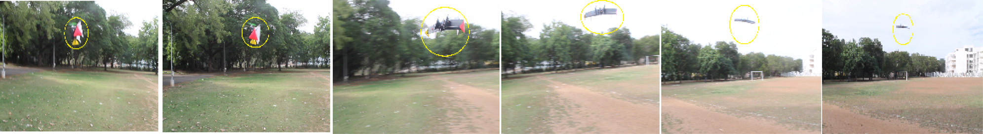
Figure 24 shows the photographs of the UAV in flight sequence during hover in windy conditions. Initially, the wind direction is perpendicular to the wing surface. Later, the vehicle changes its orientation to the minimum drag position in 5 sec. Due to heavy wind, the vehicle is seen to be drift during the course of slewing. However, the vehicle stays stable after the slew, as seen in the last two snapshots.
The transition of the vehicle from VTOL mode to horizontal flight mode is shown in Figure 25, and is found to take place in 7 sec. Transition is initiated by introducing an imbalance of thrusts between the top pair and bottom pair of motors, while simultaneously deflecting the elevons towards the transition direction.
The hybrid tilt unmanned aerial vehicle was successfully designed, developed and tested. The performance of the vehicle during hover was analysed for various wind velocities. During the test, it was observed that the drag increased for increasing wind velocities and for increased wingspan. A simple yaw control loop was applied to the vehicle in hover mode and for vertical take-off and landing. The induced drag was thus kept to a minimum by initiating a yaw shift. This was accomplished in 5 sec when the wind speed was about 6 m/s from East to West. The developed UAV also performed the entire flight loop, starting from vertical take-off, transition, horizontal flight and vertical landing. It was observed to have the advantages of being able to take off and land in minimal space, hover, and undertake long endurance flights. It can be inferred from the results that the proposed method provides more robust performance in wind disturbances and reduced power consumption.