
Abstract
Tilt-rotor unmanned aircraft vehicle has the potential to combine vertical take-off and landing capability with efficient, high-speed cruise flight. However, the mode transition process is risky owing to the internal continuous time change of aerodynamic and external uncertain wind disturbances. Gain scheduling between two modes is commonly used to achieve mode transition control. However, the optimal scheduling parameters to allocate the manipulated variables for the stable transition have not been determined to data. Focusing on this problem, a gain scheduling-based tilt angle guided robust control method for mode transition is proposed. The dynamic model is first built and analyzed based on a newly developed 360-kg tilt-rotor unmanned aircraft vehicle. Based on this model, the transition guided curve is mapped with respect to velocity and tilt angle, and it is introduced to the gain scheduling method to optimally achieve the allocation of the manipulated variables. Finally, the feasibility and validity are verified in a simulation experiment. Furthermore, the robustness is verified in simulated wind disturbance.
Introduction
Considerable research has been focused on the design and development of tilt-rotor unmanned aerial vehicles (TRUAVs), which have both high-speed cruise and vertical take-off and landing (VTOL) abilities. 1 Owing to these abilities, tilt-rotor aircrafts have wide applications in military and civil fields. The tilting angle of the rotors is variable; hence, the whole flight process of TRUAVs can be divided into three modes according to the rotor-tilt angle 2 : helicopter mode, transition mode, and airplane mode.
It can be seen from Figure 1, when the rotor’s tilting angle varies from 90° to 0°, the flight mode switches from helicopter to airplane mode. In this process, the transition control of the TRUAV is still a difficult point because of the varying in dynamics and control coupling. Besides that, the stability of the TRUAV cannot be ensured under the external uncertain wind disturbances. To deal with the above problem, many classic and novel control methods have been proposed to focus on the transition control problem of the TRUAV. A switched logic control method 3 based on a finite time convergent observer to overcome the uncertainties of the dynamics is proposed to perform the altitude tracking during the mode transition. Unfortunately, all the dynamical models used to the construction of the control law for the mode transition have reckoned without the dynamic properties induced by the tilt angle. A nonlinear attitude controller 4 based on active disturbance rejection sliding mode is proposed to focus on the disturbance control of the TRUAV. However, the control coupling during the transition process is ignored. Minimum energy controllers have been designed based on the helicopter and airplane modes. 5 But the stability during transition mode has not been considered throughout the whole process. To achieve a stable control performance of the TRUAV during the transition process, the model predictive control (MPC) method is proposed. 6 –8 However, the MPC method is designed for a single flight state. The whole transition process of the TRUAV has different flight states. The finite-time stabilization control method has been proposed 9 for different flight states during the transition process. Moreover, a time-varying linear control method for the TRUAV is also proposed. 10 The time-varying parameter control method is not applicable to different types of TRUAVs. An optimal control approach is proposed to deal with wind disturbances on the TRUAV in helicopter and airplane modes. 11 However, the wind disturbance in the flight-mode transitioning process from the helicopter mode to the airplane mode is ignored. Considering the variable and nonlinear dynamics of the TRUAV during the transition process, linear parameter varying (LPV) methods provide convenient tools for model representations and state space for nonlinear system.

Flight mode of the TRUAV. TRUAV: tilt-rotor unmanned aerial vehicle.
The LPV system contains state-space matrices that depend on varying parameters 12 ; thus, it reserves nonlinearity to a certain degree, and its linear form is beneficial for further controller design with the development of linear matrix inequality optimization. With these advantages, the LPV control method has been widely applied to aircrafts with variable structures 13 –16 for capturing the varying nature of the system dynamics. In most existing studies, the varying parameters in LPV systems are all assumed to be measurable. However, the varying parameters of the TRUAV system are unmeasurable. This means that an LPV controller for the TRUAV cannot be scheduled directly by the varying parameters. A single LPV controller designed for a single flight state cannot accomplish the whole transition control of the TRUAV operating in the transition mode. Moreover, the switching LPV control method based on the Lyapunov function is computationally expensive because it needs to solve a large number of linear matrix inequalities. 17 –23 Typical linear control methods, such as the proportional-integral-derivative (PID) and LPV control methods, cannot stabilize the TRUAV in the transition process because of the varying dynamics and control coupling. Therefore, the gain scheduling (GS) control method has been considered and adopted for the TRUAV transition control. 24 –26 The weight-control method has been designed for the transition process based on two sets of controllers. The traditional GS method 27 –31 is used with the concept of “direct-switch” between a set of linear controllers for different TRUAV linear models. However, previous GS control methods for the TRUAV based on many engineering experiences and varying dynamics characteristics are not considered. Direct switch could lead to the control coupling between the controllers and the manipulated control variables not being allocated reasonably, which will cause an unnecessary state jump. Generally, most existing transition control methods cannot ensure that the TRUAV safely and stably transits from helicopter to airplane mode. These control methods do not have a mechanism for allocating the manipulated variables between the helicopter controller and airplane controller during the transition mode. The control couple and allocation of the manipulated control variables are the key to achieving the stable control performance of the TRUAV during the transition process.
The main contribution of our work focuses on the design of a transition guided curve (TGC), which is mapped with respect to the velocity and tilt angle. Based on the designed transition curve, the GS control method can achieve the allocation of the manipulated variables optimally to accomplish the whole transition process. To deal with coupled control inputs and to decouple original dynamics on the transition mode, strict dynamics are established, simplified, and decoupled by introducing virtual control variables. By simplifying and decoupling the nonlinear dynamic model of the TRUAV, the TGC is calculated by formulating the control-weight allocation problem as a quadratic programming (QP) problem. The transition guide curve is proposed and guided to transition smoothly and safely during the transition process. Finally, flight simulation results show that the proposed control method has a better performance over the traditional GS algorithms with stronger stability.
The structure of this article is organized as follows. The second section presents the dynamic model of the TRUAV, which is prepared for designing the controller and the transition guide curve. The third section discusses the calculations and design of the transition guide curve. In the fourth section, different simulation conditions and methods are simulated, compared, and discussed. Finally, conclusions are given in the fifth section.
Dynamic model
Some necessary assumptions are needed to model the TRUAV, the details are as follows: (1) The aircraft is considered as a rigid body. (2) The center of gravity coincides with the aerodynamic center and will not change. (3) TRUAV in this article is symmetric in the x–z plane, so inertia product
The structure of the TRUAV and the coordinate systems definitions are illustrated in Figure 2. The dynamic characteristics of the TRUAV change with the angle tilt. The body-axis


TRUAV structure and coordinate system. TRUAV: tilt-rotor unmanned aerial vehicle.
where m denotes the mass, g denotes the gravitational acceleration,
Rotor dynamics model
The position and attitude of the TRUAV in helicopter mode and the early stage of the transition mode are determined mainly by the forces and moments that are generated by the two rotors. According to Zhao et al., 29 in the case of uniform airflow without external disturbances, the rotor thrust Tr can be formed as follows

where KT
denotes the constant coefficient with a constant rotor speed,


where
Aerodynamics model
The aerodynamic forces and moments are mainly generated by the fuselage, wings, and tails. According to Lu et al. 2 and Zheng et al., 32 the aerodynamic forces and moments can be represented as follows

The aerodynamic forces and moments in the body coordinate system can be expressed as follows


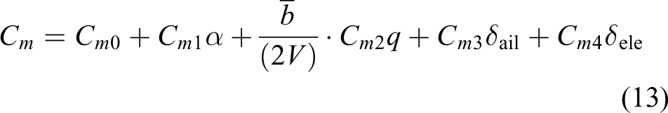


where
Dynamic simplification and decoupling
Dynamic model simplification and decoupling are the key to designing the transition guide curve. Some virtual control inputs for the controller design and dynamic decoupling are introduced and defined based on the TRUAV model as follows

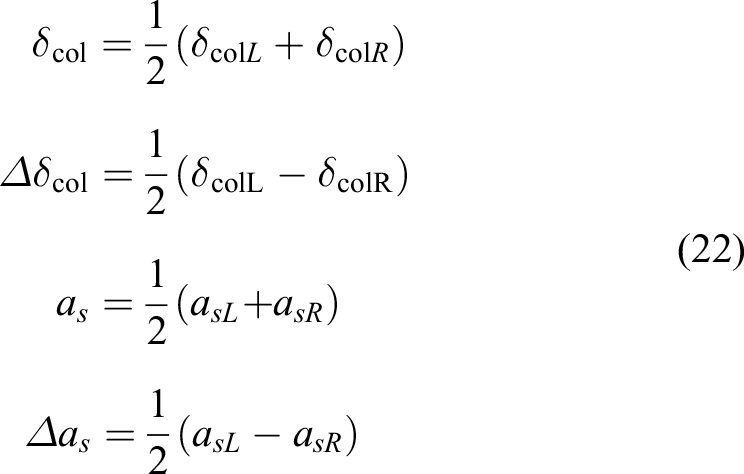
where


Coefficient matrix


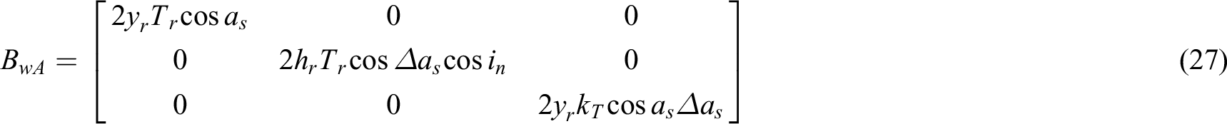

We defined vector

A novel smooth virtual input control is introduced to decouple during the transition process. The virtual input control is based on the tilt angle to adapt to the varying dynamics. The controller form of the velocity dynamic equation is proposed as follows

where

The disturbance terms including the aerodynamic interferences between rotors and other minor parts are as disturbance term vector
Transition guide curve
The TGC is built by calculating a series of control state-balance points based on the tilt angle of the TRUAV. The control-weight allocation problem is formulated as QP problem.
The equations with respect to velocity and the tilt angle can be represented as follows

The TGC is illustrated in Figure 3. The rotor’s tilt angle is guided by the transition guide curve to satisfy the flight velocity. A reasonable control-weight allocation will allow the TRUAV to safely transit from helicopter mode to airplane mode based on the transition guide curve.
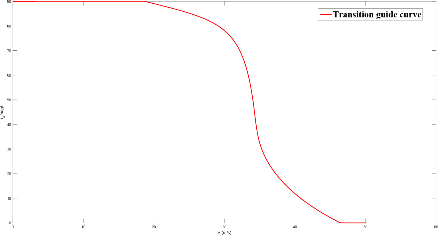
Proposed transition guide curve with respect to velocity and the tilt angle.
The controller included an outer loop controller (position controller) and an inner loop controller (attitude controller). As is seen in Figure 4, they are both based on the P-PI controllers. KP
is the position-proportional parameter,
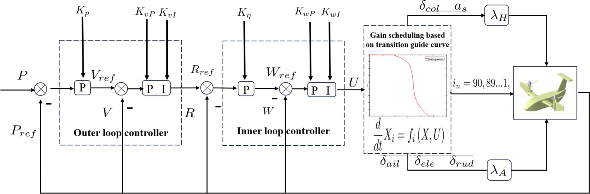
GS control structure.


Different gain-scheduling frameworks for the transition process. W is defined as the helicopter control-weight coefficient, and
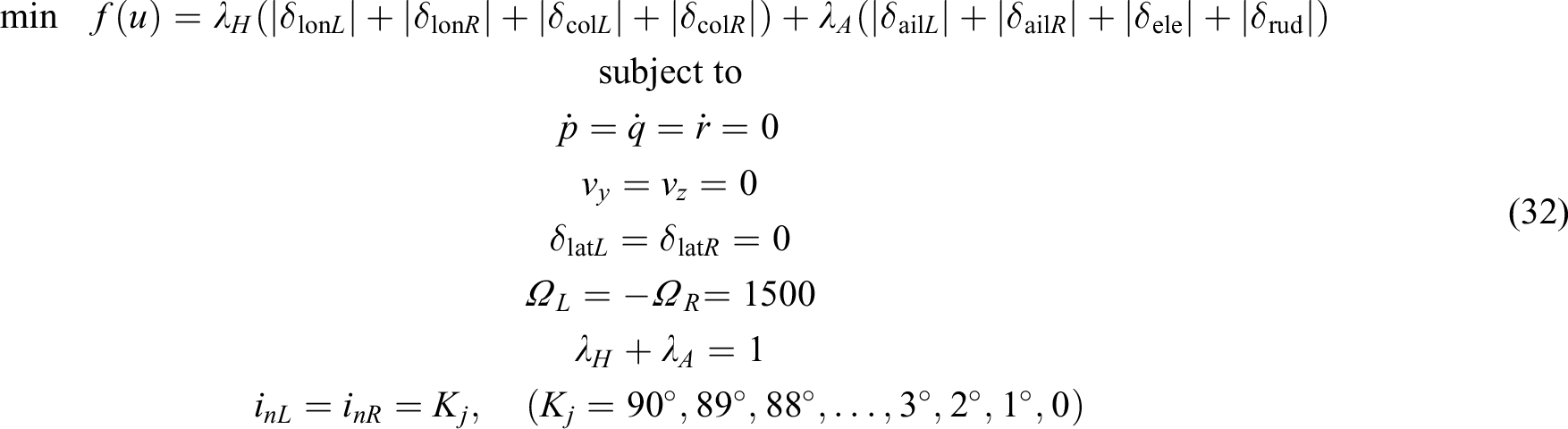
Based on the x 1, x 2, the cost function equation (32) can be simplified as follows

Let

The control-weight allocation problem is formulated as QP problem, and control-weight coefficient can be solved by OSQP. The transition process began at 19.3s end in 33.4s. The control-weight coefficient values are listed in Table 1.
Control-weight coefficient values on the transition process.

Simulation experiment
To demonstrate the performance of our control method, the normal and disturbance flight modes are simulated and verified in the simulation experiment. The parameters of the TRUAV are listed in Tables 2 and 3.
Controller parameters of the TRUAV.
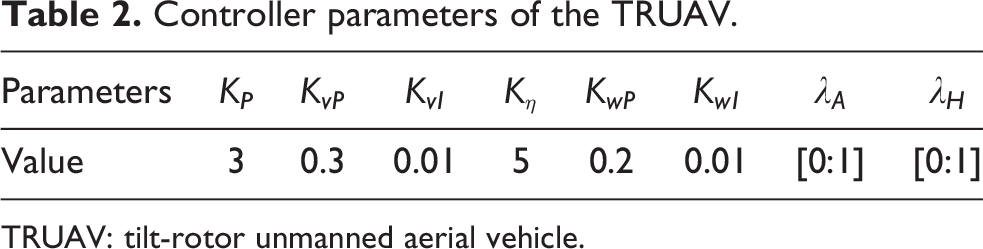
TRUAV: tilt-rotor unmanned aerial vehicle.
Parameters of the TRUAV.

TRUAV: tilt-rotor unmanned aerial vehicle.
Different transition curves of the TRUAV are illustrated in Figure 6, the blue line is the tilt guide curve proposed in our method, the pink and red lines are two transition curves formed from the previous direct-switch control method. The pink line tilt acceleration is a = 6.4°/s and the red line tilt acceleration is a = 11.2°/s. It can be seen in Figure 6 that the pitch degree of the pink line has a significant jump point at t = 26.3s. The UAV crashed during the transition process in the previous direct-switch method. Both the blue transition curve and pink line curve can successfully enable the transition from helicopter to airplane mode.

Transition curve of the TRUAV. TRUAV: tilt-rotor unmanned aerial vehicle.
In the normal flight experiment without disturbances, the green curve represents the previous weight-GS control method. The blue curve represents the proposed control strategy based on the transition guide curve. The main state variable values of the TRUAV are illustrated in Figure 7 and Figure 10. The TRUAV took off to a 20 m altitude in helicopter mode; acceleration began after 11s. The transition mode began when the airspeed reached the minimum velocity of the tilt curve (18.3 m/s). However, the vertical velocity based on the previous weight-GS control method had a severe step response at 24.7s and a big jump in the flight altitude. The flight height was also kept at 20 m during the entire transitioning process. When the flight speed reached 46 m/s (t = 33.4 s), the rotor-tilt angle switched to 0° and successfully entered the airplane flight mode. Subsequently, the transition from helicopter mode to airplane mode was realized, and the system was taken over by the airplane mode controller. Finally, the forward speed of the TRUAV was stable at 50 m/s, and the lateral and vertical speeds were stable at 0 m/s.

Main state variable of the TRUAV in transition process from helicopter to airplane mode. TRUAV: tilt-rotor unmanned aerial vehicle.
The attitude information of the TRUAV is illustrated in Figure 8 and Figure 11. The pitch angle was negative value. Because the TRUAV needed to accelerate on a fit attitude similar to “head down.” When the tilt angle began to increase, the component of the rotor tension in the horizontal direction and the role of the aerodynamic force of the system gradually increased. Simultaneously, the pitch angle increased, and the attitude of the TRUAV tended to be horizontal. The proposed control method on the roll-angle

Attitude state variable of the TRUAV in transition process from helicopter to airplane mode. TRUAV: tilt-rotor unmanned aerial vehicle.
The control input of the TRUAV is illustrated in Figure 9 and Figure 12. In the initial stage, the control inputs were mainly from the helicopter control input
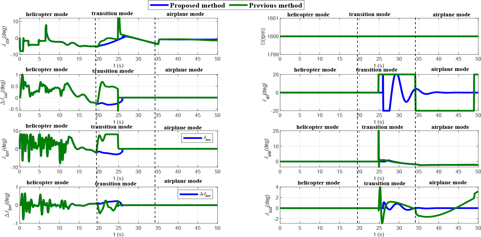
Control input variable of the TRUAV in transition process from helicopter to airplane mode. TRUAV: tilt-rotor unmanned aerial vehicle.

Main state variable of the TRUAV in transition process from airplane to helicopter mode. TRUAV: tilt-rotor unmanned aerial vehicle.

Attitude state variable of the TRUAV in transition process from airplane to helicopter mode. TRUAV: tilt-rotor unmanned aerial vehicle.

Control input variable of the TRUAV in transition process from airplane to helicopter mode. TRUAV: tilt-rotor unmanned aerial vehicle.
Absolute mean tracking errors of TRUAV state variables.

TRUAV: tilt-rotor unmanned aerial vehicle.
To demonstrate that our control method has a greater potential control margin to reject external disturbances, two comparative experiments were conducted to compare our method to the traditional gain-scheduling (GS) method. The GS control method experiment performance is illustrated in Figure 13. The blue line represents the normal mode without external disturbances, and the red line represents the disturbance mode. The external disturbance was simulated at 27.3s. It is constant values with 399 N. The roll angle

Experiment with the previous GS control method. GS: gain scheduling.

Experiment with proposed control method.
Conclusion
In this study, a hierarchical GS control method based on the TGC is designed to smoothly switch between modes of TRUAV. A reasonable control-weight allocation and minimum energy consumption will enable the system to have a greater potential control margin to reject external disturbances. In contrast to the previously implemented GS control method, the rotor-tilt angle is regarded as a control input, and a virtual control variable including more than one control input is considered to decouple original dynamics. The simulation results show that the proposed control performance is much better than the traditional GS control method. We have inherited our GS control algorithms into our flight controller. In addition, the 360-kg flight platform has been designed and completed. The proposed control method will be tested on the designed 360-kg TRUAV, in a real flight experiment in the future.
Footnotes
Declaration of conflicting interests
The author(s) declared the following potential conflicts of interest with respect to the research, authorship, and/or publication of this article: The author declares that the research was conducted in the absence of any commercial or financial relationships that could be construed as a potential conflict of interest.
Ethical statement
This manuscript describes original work and is not under consideration by any other journal. All authors have approved the manuscript for submission and without any potential competing interests.
Funding
The authors disclosed receipt of the following financial support for the research and/or authorship of this article: This work was supported by Chinese National Natural Science Foundation (grant nos. 91948303 and 61991413), Local science and technology projects guided by the Central Government of Liaoning Province (grant no. 2022JH6/100100009), Key support from NSFC Joint Fund (grant no. U22B2041), and NSFC Science Fund for Innovative Research Groups (grant no. 61821005).