
Abstract
Climbing robots have been widely used to inspect smooth walls. However, a good adsorption method has not been found for the inspection of a cliff surface and a dusty high-altitude surface with small vibration, both of which are made of coarse concrete, square brick, or rock. In this article, first, we analyzed the bionic structure of the cockroach legs and observed their morphological characteristics of the spiny claws on these legs. We also studied the interaction theory of the bionic claw with the bulges on the rough wall surfaces and deduced the mechanical criteria of the claws grabbing steadily these bulges. Then, an initial mechanical structure of a wall-climbing robot was proposed based on a grasping claw and a climbing model. Furthermore, a mathematical model was established to reflect the relationship between sharp hooks and bulges on the rough wall. Finally, we performed several laboratory experiments to verify the grasping stability.
Introduction
Construction accidents have occurred in recent years, causing serious damage such as collapse of bridges. Some examples of these are the accidents that have occurred at St. Nazaire Bridge in France, 1 Kohlbrand Estuary Bridge in Germany, Luling Bridge in the United States, 2,3 and Phoenix Bridge in Hunan, China. The maintenance cost of such structures was more than half of their overall construction cost. Therefore, periodic inspection is needed to guarantee the safety of special structures, such as cable-stayed bridge pylons, nuclear reactor buildings, and viaducts in remote mountainous areas. However, the cracks and roughness of the wall surface of such structures easily induce air leakage on a suction device. The surface must be composed of magnetic materials for magnetic adsorption to occur. Dust on the surface, as well as temperature and humidity of the environment, affects the bionic adhesive adsorption. Thus, traditional adsorption that meets the requirements for climbing such a wall surface is difficult to implement. The study of a new adsorption method and a lightweight climbing robot to inspect these rough wall surfaces has become an interesting research direction with the progress of robotic technology.
Some researchers proposed a bionic grasping “adsorption” mean and proposed a variety of bionic climbing robots through investigating the excellent characteristics of the minute claws of bumblebees and beetles. Spenko et al. 4 designed a series of robots, one of which was called RiSE climbing robot. This mechanism was hung on the wall through some minute steel claws. This robot could conveniently transform between a tree-climbing and a ground-walking one through the transformation of 6-ft modules by integrating bionics into traditional design and using modular combinations. Goran et al. 5 designed a bionic climbing robot called DynaClimber according to the biological climbing model. The climbing velocity of the DynaClimber was significantly improved compared with that of the previous prototype. Sebastian et al. 6 designed a 6-ft climbing robot called Space Climber using the bionics principle. This robot could move freely in extreme environment. Sintov et al. 7 proposed a hook-like wall-climbing mechanism, which was applied to surveillance, rescue, observation, and recreational activities. Full et al. 8 proposed a bionic robot, RHex, to maximize effective distributed leg contact through changing leg orientation and adding directional spines, which improved RHex’s ability on some challenging surfaces without adding any sensors. Lam et al. 9 –11 designed a tree-climbing robot that could cross tree-like branches and had a claw-type and new flexible motion structure. The robot weighed 600 g and could bear a load up to 1.75 kg. It could stably grab irregularly shaped objects, such as tree trunks, and completely enclose them in its hooked claw. Researchers from Stanford University also proposed a bionic wall-climbing robot called SpinyBot. 12 The robot can climb on the rough concrete and brick walls as the tiny claws on the feet could “grab” the rough bulges on the wall.
Many researchers improved the mechanism of the suction to retain the merits and decrease the demerits of the conventional method. Dai et al. 13 studied the claw microstructure, living environment, and surface morphology of bumblebees and designed the bionic claws. The researchers found that the hook on the front end could grasp the concave and convex points of the rough wall, thus the robot was hanged on the wall surface to climb during the bending process of the three tarsals on the claw. Chen et al. 14 developed a rough wall-oriented crawling robot with a sharp claw-structured toe. The toe pinched into the coarse wall surface to complete adhesion. Guan et al. 15,16 developed a modular double-claw robot capable of completing hazardous tasks in a high-altitude and complex environment. Chen et al. 17 designed a hopping robot based on the bionic research on locusts. Using gecko-like fibrillar adhesives, some researchers proposed a novel wall-climbing mechanism called Waalbot II. 18 The robot could climb on both rough and inverted smooth surfaces. Other novel robotic mechanisms were Abigaille II, 19 the optimized multi-agent, 20,21 climbing robot, 22 legged robot on the water 23,24 and Abigaille III, 25,26 which could climb on vertical surfaces, using miniaturized motors to drive it and gecko-inspired dry adhesives to stick to various surfaces.
The previously discussed robots can grasp onto the bulges on the rough wall surface under gravitational force or stick on the wall surface through van der Waals forces. However, the adaptive ability of claws to vibrating rough wall surfaces and dusty wall surfaces were not investigated. Furthermore, the existing wall-climbing robot with grippers is mainly utilized on the rough and static wall. When these robots are applied to the vibration walls, the hanging gripper may fall off. As for the detection or exploration of this kind of rough walls, the structure of the grasping gripper for the climbing robot is suitable.
The remainder of the article is organized as follows. Section “Interaction mechanical mechanism of bionic hook with rough wall bulges” introduces the structural characteristics of the spines on a cockroach leg and proposes a moving gait model and a mathematical judgment model for the stable grabbing of a single hook. Section “Grasping claw based on torsional spring” proposes a grasping claw based on torsional spring. In section “Robot design and laboratory tests,” the multi-feet wall-climbing robot designed based on the mechanism of hooked claws was presented. Some laboratory tests are also carried out in this section. Section “Conclusion” provides the conclusions and the following research directions.
Interaction mechanical mechanism of bionic hook with rough wall bulges
Traditional vacuum adhesion and magnetic adhesion robots are seldom used for the inspection of high-altitude buildings, such as cliffs, irregular water brush stone, rough concrete walls, and rocks with large cracks (Figure 1). On the contrary, some animals with sharp minute hooks or claws on their legs, such as cockroaches and ants, can easily climb on these surfaces. The minute spine structure on the soles of these animals can grab tiny bulges on the wall.
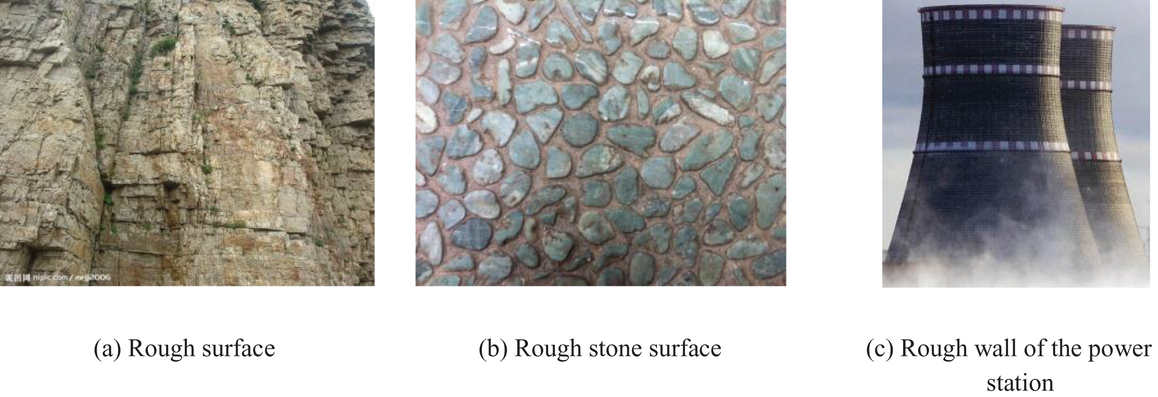
Rough wall surfaces.
In this section, we designed a microbionic structure to implement a flexible climbing mechanism suitable to climb on a rough wall. Taking the cockroaches as the biological prototype, we analyzed the minute spine structure of their legs and researched the interaction mechanical mechanism between the hook and the bulges on the rough wall. Thus, we deduced the criteria conditions for the hooks to grasp these bulges steadily.
Bionic analysis of the spine structure on the cockroach leg
Cockroach feet and legs have many small claws and minute hooks for adsorption on rough or smooth wall. Figure 2 shows that these minute hooks grasp the rough convex points of the concrete wall instead of penetrating in the inward wall. The cockroach leg is generally composed of trochanter, setae, spines, tibia, femur, and tarsal. The spines and claws are some tiny hooks at the end of these legs. Through these spines, cockroaches can steadily grab the bulges on rough wall.

The structure of a cockroach.
A cockroach climbs fast even on a rugged rough wall. It does not decrease the climbing velocity even on a cragged vertical surface. It moves with three legs on the wall, that is to say, the metapedes on the one side and the propodeum on the other side, which form a triangular supporting structure. In the climbing process, three legs contact with the wall and kick backward, the other three feet are lifted to creep forward. A cockroach uses the propodeum to grasp the bumps and pull its body forward as well as the metapedes to support and uplift its body. The metapedes pull the whole body forward and rotate it. Its body is positioned forward and slightly turns outward while climbing forward. The movement forms a jagged line instead of a straight line. Using such an “alternating triangle” pace, the triangular support is achieved while three legs lift off the wall. Thus, a cockroach can climb on various types of walls in a balanced state through regulating center of the gravity based on the three supporting legs.
Climbing gait of the cockroach and climbing model of robot
When a cockroach begins to move, as Figure 3 shows, number 4 of the left leg and numbers 1 and 5 of the right leg are lifted and get ready to swing forward, while leg numbers 2, 6, and 3 support the body to ensure that its gravity center in the triangle is constituted by supporting the legs (Figure 3(a)). Subsequently, the swung leg numbers 1, 4, and 5 step forward (Figure 3(b)), while leg numbers 2, 6, and 3 support the body and drive it forward by a half step length e simultaneously (Figure 3(c)). As the body moves in place, leg numbers 1, 4, and 5 immediately lower to form a stable triangular support again. Meanwhile, leg numbers 2, 6, and 3 are lifted up and moved forward (Figure 3(d) and (e)), whereas leg numbers 1, 4, and 5 support the body and drive it forward by a half step length e simultaneously (Figure 3(f)). Thus, the cockroach moves forward by constant circulation. 27
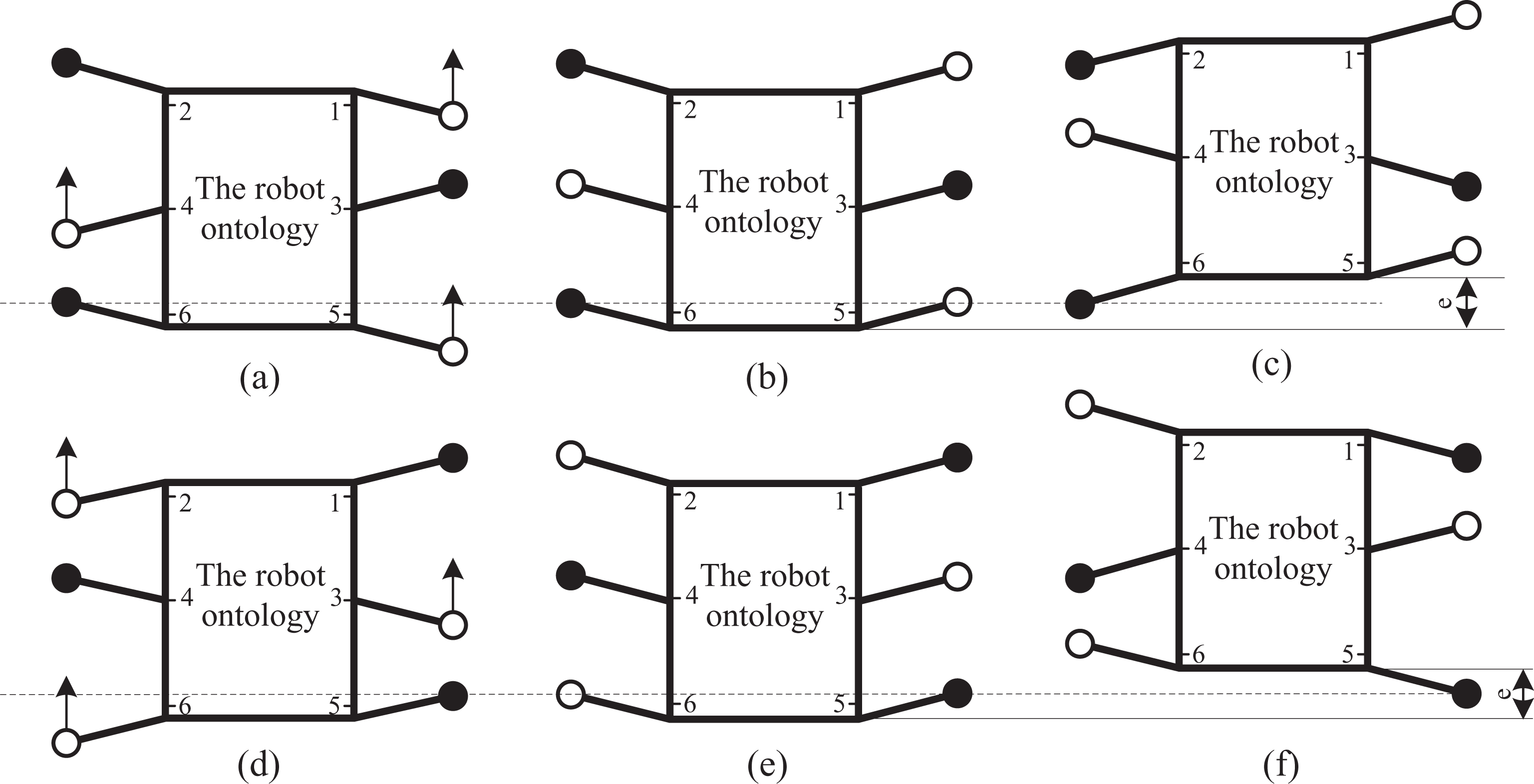
Climbing triangle gait of robot.
The results of the bionic observation experiment of the cockroach indicate that the body of the cockroach does not show pitch or rollover and gravity center height variations as the cockroach crawls at normal speed on the flat ground. We designed a 6-ft model of the wall-climbing robot according to the movement gait and the interaction mechanism between the hook and the rough wall surface. The moving principle of the robot can be described using a parallelogram mechanism (ABCD, Figure 4). Hooked-claw modules 1, 4, and 5 are connected to a connecting rod of the parallelogram mechanism; modules 2, 3, and 6 are fixed onto the other connecting rods of the parallelogram mechanism. These modules are driven by a steering engine as they grasp microprotuberances on a wall. The main motor is installed at point O, causing the drive rod to swing back and forth within the predetermined range of angle. Two sets of hooked claws move up and down alternately and grab the microprotuberances on wall surfaces to climb. Therefore, the triangular support and climbing state of the cockroach motion were simulated.

Climbing model of robot with 6 ft.
As the robot is a parallelogram mechanism, meanwhile, hooked-claw modules 5 and 6 can be omitted if the robot only climbs up and down. Therefore, we tried to simplify the model to a quadrangle (ABCD), from which we can determine the climbing gait of the robot (Figure 5). When the robot climbs up vertically, the gait includes two steps; that is, the two edges move up alternately.

The movement gait of the robot.
Judgment condition for bionic claw grasping steadily bulges on rough wall
We picked out some sampling points on an arbitrary rough wall (artificial wall surfaces with different roughness were constructed in the laboratory). Then, using a portable three-dimensional scanner, the distance from the wall surface to the base surface was measured and the original data of rough bulges were obtained. We obtained the curve to describe the wall bulges by fitting the data collected using a polynomial. Three types of curves (A, B, and C) were deduced (Figure 6(a) to (c)) according to the characteristics of curves and the cycle division on the curves (the period between two peaks is a cycle).
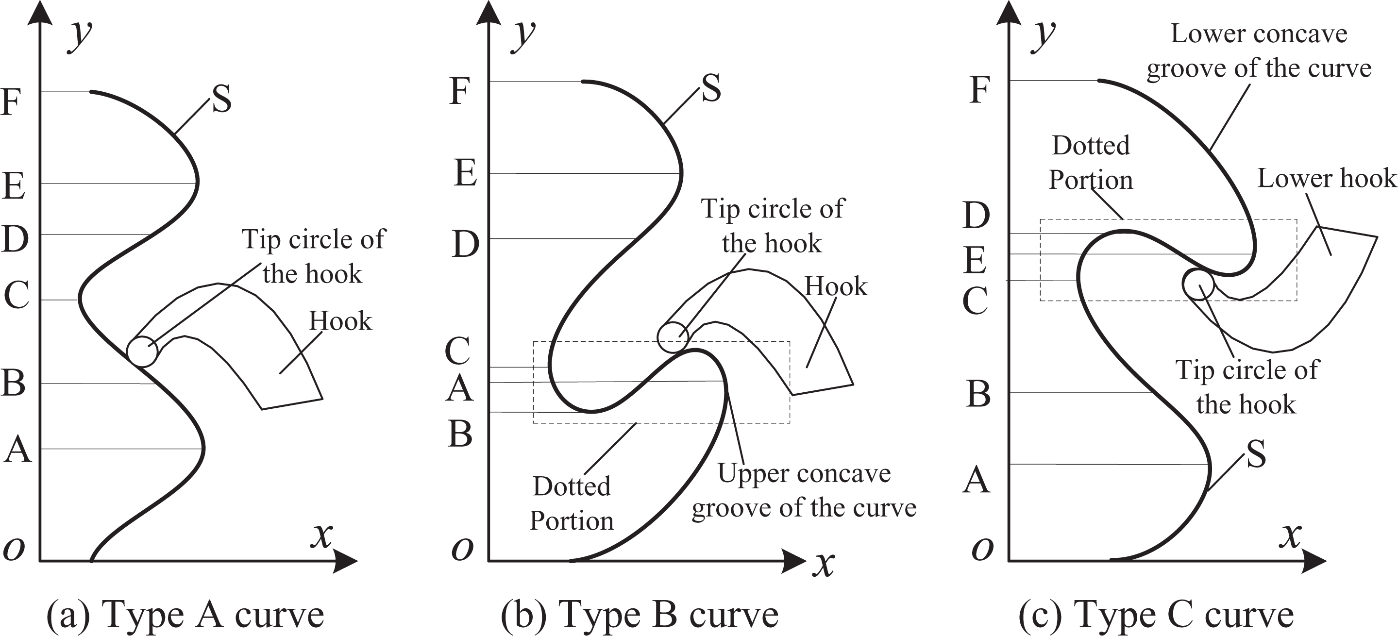
Mechanism of hook grabbing bulges on the rough walls.
In type B curve and type C curve, we only pay close attention to the dotted portion. The type B curve has a concave groove, that is, a y value is corresponded to multiple x values. Thus, the claw can directly hook the concave groove; as for type C curve, the lower hook instead of the upper hook is incapable of grabbing the concave groove. In addition to the concave groove, the analysis on type C curve can be in reference with that on type A curve. Therefore, it can be seen that the hook can grab the type B and C curves stably. Therefore, only the type A wall surface should be analyzed emphatically.
For the type A curve and the force analysis in Figure 7, the equations F sin β < N μ and F cos β = N should be satisfied for the hook to attach steadily to the rough bulges. Therefore, β < arctan μ, that is

Force analysis of the hook.

where α is the normal angle, that is, the angle between the normal directions of the hook–bulge contact point with vertical plane, μ is the frictional coefficient, and θ is the grabbing angle, that is, the angle between the grabbing force with the negative direction of the y-axis. The condition of equation (1) should satisfy the principle of friction self-locking. AE is a cycle of type A curve. The upper hook is incapable of completing the grab in section CE. The grabbing condition should be judged using equation (1). As the hooks slid along the wall surface from top to bottom, the grabbing is successful in regards to the case of equation (1).
Grasping claw based on torsional spring
In this section, a wall-climbing robot model was built according to a grasping claw modeled on wall-climbing cockroaches. Then, the force analysis based on equation (1) is carried out.
The structure of the grasping claw
Figure 8(a) is the grasping model based on the torsional springs. The principle of this model is as follows: an eccentric wheel mechanism is driven by a micromotor, a small roller is placed between the pressure plate and the hooked claw, and a torsional spring is installed on every hooked claw. When the pressure plate is moved downward, all of the hooked claws will stretch. Therefore, the claw is detached from the bulges on the rough wall. When the pressure plate is pulled back, every hooked claw grasps the rough bulges independently under the action of torsional springs. The pressure plate will continue to draw back when some claws contact with the bulges. At this time, other sharp claws would continue to search other graspable bulges.

Grasping model based on the torsional springs.
Figure 8(b) shows the distributed architecture of these minute claws. Two pairs of claws are placed on the upper and lower parts of the module. Another pair is installed on the left and right sides to increase the stability of the mechanism. The torsional spring drives each hooked claw to move independently, thereby improved the stability of the firm grasp of bulges on the rough wall.
In the climbing module, the bulges on the rough wall provide the mechanism with an adsorption force pointing toward the inward wall. The constraint imposed by the wall budges on the robot is increased, which helps the robot resist the wind load in high altitudes and decrease the effect of wall vibration.
Force analysis of the grasping claw
We took the claw with minimum hooks (such as two hooks arranged on the upper and lower limbs) as an example to analyze the interactions between the grasping claws and the wall surface. Then, we studied the mechanical performance of the hooked claw when grasping the surface bulges.
Figure 9 shows the stresses exerted on the hooked claw according to the climbing models constructed in the previous section. The direction of friction Ff2 on the lower claw tip is directly related to the torque magnitude of the torsional spring. When τ2 > τ0, Ff2 points downward along the tangent plane of the bulge. When τ2 < τ0, Ff2 points upward along the tangent plane of the bulge. When τ2 = τ0, Ff2 = 0. In this study, τ0 is the critical value of the torque of the torsional spring, τ1 and τ2 are the exerted torques of upper and lower hooked claws.

Analysis of stresses on hooked claw.
We can obtain the following equation according to the equilibrium conditions

The torques of the torsional spring on the upper and lower hooked claws are calculated as follows

The angles of the upper and lower bulges are set to be equal to simplify the problem; that is, θ1 = θ2 = θ and Ff1 cos θ > N1 sin θ for the upper claw. Thus, Ff1 > N1 tan θ. Therefore, the angles of bulges must be smaller than the self-locking angle between the claw tip and the bulge, that is, θ < arctan(μ). Otherwise, the upper claw slides away and does not grasp the bulges steadily.
The following equation can be derived by analyzing the contact points on the lower hooked claw

Then, we can derive

In these equations, N1 and Ff1 are the support force and friction exerted on the upper claw tip by the bulge, respectively, Fs1 and Fv1 are the tangential and normal forces along the wall surface of the support force and friction exerted on the upper claw tip, respectively, N2 and Ff2 are the support force and friction exerted by the bulges on the lower claw tip, respectively, and Fs2 and Fv2 are the tangential and normal forces along the wall surface of the support force and friction exerted on the lower claw tip, respectively. C is the mass center of the whole hooked claw, τ1 and τ2 are the torques of torsional spring for the upper and lower hooked claws, respectively, θ1 and θ2 are the angles of the upper and lower bulges, respectively, and F is the resultant force on the upper and lower hooked claws.
Equation (5) calculates whether the self-locking of the upper hooked claws is related to the angles of bulges and the supporting forces (the torque of torsional spring) of the upper claw (Figure 10). S1 is the curved surface of the static friction of the upper hooked claw and S2 is the curved surface of its sliding friction. The smaller the bulge angle is, the larger are the supporting force and static friction exerted on the upper hooked claw. Moreover, the self-locking of the upper hooked claw will obtain more easily. The static friction exerted on the upper hooked claw exceeds the sliding friction when the bulge angle is larger than a certain value. Then, the hooked claw slides away and does not grasp the bulges steadily.

Self-locking of upper hooked claw.
Robot design and laboratory tests
To verify the feasibility of mechanical grasping on the rough wall surface through the minute claws, a simple climbing prototype was fabricated in the laboratory. Moreover, a control system was designed for preliminary experiment. The laboratory conditions were as follows: Two artificial walls with different roughness were constructed using wood trusses filling cement and stones, which measured 1.2 m × 0.6 m (Figure 12(a)). The angle of inclination of the wall surfaces could be adjusted arbitrarily. In addition, the walls were similar to the granitic plaster surface in the actual construction application. Several random rough walls were placed in vertical direction; while some relatively smooth horizontal ground was applied.
Motion control system of the robot
The motion control system of the climbing robot includes the main control unit (MCU), the motor driver unit, the detecting unit of velocity and displacement, the serial communication unit, and the wireless transmission unit (Figure 11).

Motion control system for wall-climbing robot.
The principal computer sends the instructions and data to MCU. The principal computer is also responsible for completing data processing. The status messages of the motors can be determined through the optical-electricity encoder, thereby providing Proportion Integration Differentiation (PID) data for MCU.
The motion controller, which is the MCU of the motion control system, can complete the following tasks: Receives the motion instructions from the principal computer and returns the motion status (location and input/output (I/O) signals) to the principal computer. Completes the motion control (location and velocity) based on the instructions received. Deals with the external I/O signals connecting with motion.
Climbing tests in the laboratory
In the laboratory, a climbing robot was designed using a plastic plate, and some climbing tests were carried out on rough, inclined, and vertical rough or smooth concrete walls (see Figure 12). The experimental results indicated that steering and obstacle avoidance can be controlled, and the designed mechanism could climb over some small obstacles or gaps. The maximum obstacles the robot can climb are mainly affected by the dimension of the robot, the claw point, and the swing angle of the claw box. The main parameters of the robot can be seen in Table 1. The dimension from wall surface to the robot’s center of mass is 20 mm. We can conclude that the maximum obstacle the robot can climb is about 12 mm. Beyond this value, the robot encounters some difficulties. The climbing ability could satisfy the requirements for various rough concrete walls, such as rough cliff surface, rough brick, and rough concrete walls (see Figure 12(a)). According to the theoretical analysis and lab tests, we conclude the major technical parameters of the inspecting robot are as follows:
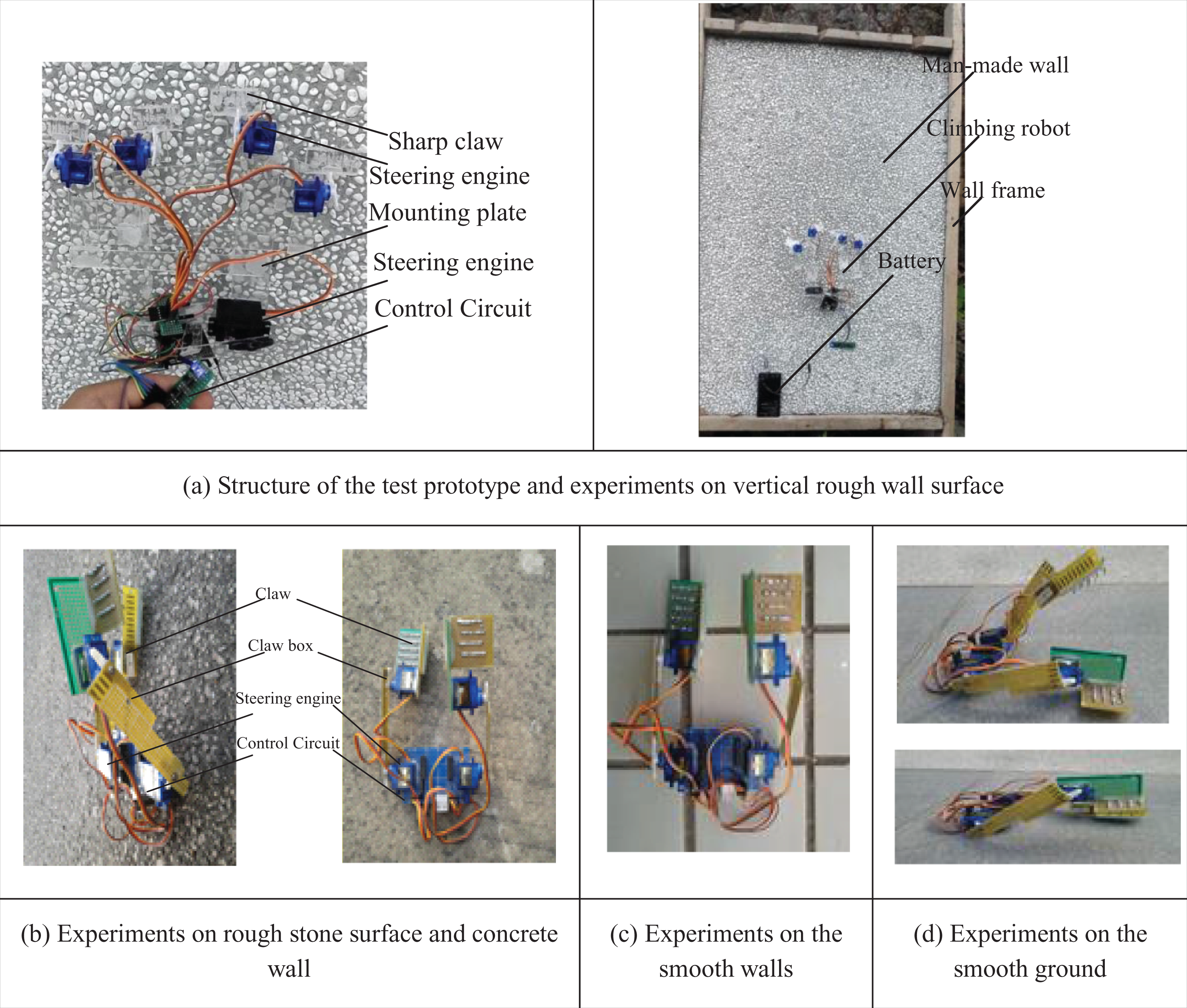
Climbing mechanism and laboratory experiments.
Technical parameters of the robot.
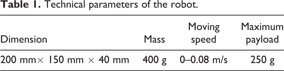
When the payloads are below 0.25 kg, the robot can climb along the walls inclined at any angle.
The robot can be installed on a cable by only one worker.
Moving speed is adjusted to a range of 0–0.09 m/s.
The maximum climbing obstacle height is 12 mm.
As there are all kinds of gravels on the surface of rough concrete walls, no cases of failure claw grasping appeared (see Figure 12(a) and (b)). For some smooth bricks, the claws can only grab the connected seams (see Figure 12(c)). However, for some smooth walls with little or small-size bulges, the grasping claw often fails to grasp the wall steadily according to some experimental cases. Therefore, when the surface is smooth, even for the horizontal ground, the claw can’t grasp the concrete surface steadily.
Tests on the loading ability of a single hook
Some loading tests were carried out in the laboratory to prove the strength of a single man-made claw. The usual shape and morphology of the hooks are shown in Figure 13(a). The force condition exerted on the hook was measured through a dynamometer when the hook grasps bulges of the rough walls. The results revealed that in case of self-locking, the hook did not slide along no matter how much force is imposed. For the hook without quenching, the exerted force increase led to the bending deformation of the hook (see Figure 13(b)). If the force exerted was large enough, the quenched hook revealed cracks or even breaks. However, the bearing force was increased obviously; in the absence of self-locking, a sliding phenomenon was occurred. For the same rough concrete walls, the smaller the hook top size, the lower the occurrence probability of sliding away. Therefore, the size of the hook must be within the scope of design criteria, and the size of the tip point should accord to the basic standard of “the smaller, the better.”

Deformation of the bionic hooks.
Conclusion
In this article, the interaction theory between the claw and the microprotuberance on the rough wall was studied according to the bionic structure of the spines on the cockroach legs. Based on this research, an innovative grabbing bionic hooked claw and a climbing mechanism was designed. The proposed sub-claw contained many bionic hooks that could move freely. If the individual claw tip was detached from the wall surface, then the separated hook tip could rapidly seek the second grabbing point for the secondary grasping under the effect of low stiffness spring. Moreover, the results of the simulation results and laboratory experiments proved that the proposed grabbing claw could steadily grasp the small bulges of the rough concrete wall.
The present study focuses on the bionic grasping claw model, which is expected to become a foundation to develop a wall inspection robot that can be used on unstructured curved surfaces with large curvature, such as rough concrete wall surfaces, rooftops and power poles, or dangerous cliffs. Further research will concentrate on designing a climbing robot to investigate and prove the performance of the entire grasping claw.
Footnotes
Acknowledgment
This article is a revised and expanded version of an article entitled ‘Analysis, Design and Experiments of a Rough Wall Climbing Robot Based on Grabbing Claws’, which is presented at The 2015 International Conference on Climbing and Walking Robots (CLAWAR 2015) held in Hangzhou, Zhejiang Province, China, September 6–9, 2015. 28
Declaration of conflicting interests
The author(s) declared no potential conflicts of interest with respect to the research, authorship, and/or publication of this article.
Funding
The author(s) disclosed receipt of the following financial support for the research, authorship and/or publication of this article: This research is supported by the Natural scientific research fund of Nanjing University of posts and telecommunications (NY214071) and Natural Science Foundation of Jiangsu Province of China (BK20151505). This research is also supported by the National Natural Science Foundation of China (51005046).