
Abstract
This article describes an adaptive fuzzy/proportion integration differentiation (PID) compound control scheme to promote the disturbance rejection ability of an aerial inertially stabilized platform. To deal with the serious influence of predominant unbalance torque disturbance on the steady precision of inertially stabilized platform, dynamic modeling and simulation analysis are conducted, which reveal that the unbalance torque disturbance is nonlinear and time varying. Then, an adaptive fuzzy/PID compound controller is designed that can automatically adjust and control parameters of the system in real time. In this way, the effects of unbalance torque disturbance on control performance are suppressed greatly so that the pointing accuracy and stability are obviously improved. To validate the scheme, the simulations and experiments are conducted to a real three-axis inertially stabilized platform. The results show that under the environment of unbalance torque disturbance, the inertially stabilized platform could reach better dynamic performances by the compound scheme, leading to the high pointing accuracy and stability.
Keywords
Introduction
Inertially stabilized platform (ISP) is now widely used in aerial remote sensing system to get high-resolution images. It can effectively restrain the influences of undesired disturbance factors on sensor’s line of sight (LOS) so as to get high-quality remote sensing images. 1 –4 Generally, an aerial remote sensing system consists of four main components, 5 that is, a three-axis ISP, one or more imaging sensors, a position and orientation system (POS), and an aviation platform. The chief role of ISP is to hold and control the LOS to keep steady relative to inertial space or maintain sensor’s orientation toward the target. 5,6 When the aviation platform rotates or jitters, the control system of ISP gets the high-precision attitude reference information measured by POS and then routinely controls the LOS of imaging sensor to achieve the high pointing accuracy relative to ground level and flight track. In order to obtain high-resolution images and satisfy the requirements of a high photo overlapping ratio, the sensor’s LOS must be strictly controlled. Therefore, the ISP with high control precision is indispensable to isolate disturbances derived from diverse sources, 7,8 particularly for the case of swings of three angular attitudes of aircraft.
Unfortunately, ISPs usually suffer from a variety of disturbances, such as model uncertainties and unexpected torque disturbances. These disturbances generally show an essential feature of nonlinearity, which has a serious influence on the improvements of the control precision. 9 In the study by Masten, 2 the common ISP disturbances are summarized systematically. Among them, unbalance, friction, vehicle motion kinematic coupling, and sensor noise are predominant. When nonsymmetry and multiaxis rotations are present, the imbalance torque will occur. Therefore, the entire rotating assembly should be balanced about the suspension pivot axis to minimize imbalance torques due to linear vibration. 3 So, the influence of stabilization platform caused by imbalance torque is more serious than others. The imbalance torque is a nonlinear and time-varying disturbance, which means that an adaptive controller with strong disturbance rejection ability needs to be developed.
To achieve the high stability accuracy, it is a principal issue for the control system of ISP that how to minimize the effects of disturbances introduced on the ISP. 2 There are continuous interests for researchers to investigate the control methods with higher accuracy and stability by rejecting various disturbances. Many approaches have been proposed to control such a complex mechatronic system. In the study by Zhou et al, 1 an inverse system method combining with the internal model control is employed in the decoupling control of a two-axis ISP. In another study, Zhou et al. 5 present a dual-rate-loop control method based on disturbance observer (DOB) of angular acceleration for a three-axis ISP to estimate and compensate the disturbance torques. In a study by Zhu, 10 a DOB to estimate the disturbing torque and calculate the voltage for compensation is proposed to a three-axis ISP. A three closed-loop proportion integration differentiation (PID) compound control scheme is applied to a two-axis ISP in the study of Zhou et al. 11 In the study of Martin and Zdenek, 12 a feed-forward solution is applied to the double gimbal platform to improve control performance. In the study of Albus, 13 an active disturbance rejection controller is used to compensate friction disturbance.
As an intelligent control method, fuzzy control is a non-open-loop control system that is based on fuzzy logic inference and microcomputer control method. It is especially suitable for the control of nonlinear, time-varying, and delay systems. 14 Traditional PID control needs accurate mathematical model, which has the long adjusting time and the overshoot error. However, the dynamic property of PID is poor, while it has high precision and stability. Comparatively, the fuzzy control method has excellently dynamic adaptive ability to the nonlinear and time-varying disturbances, by which the adjusting time is shortened and the overshoot is decreased. The most important feature of fuzzy control is that it does not require an internal mathematical model or transfer functions, and it can deal with the uncertainty related to information concerning several parameters. 15,16 However, the steady-residual errors in fuzzy control are always existed. So, the steady-state performance of fuzzy control is worse than that of traditional PID, while its robustness is higher than PID. 14,17,18 The fuzzy control theory was based on field expert’s knowledge and experience, and it depended on knowledge rules and inference process. All the parameters including the initial ones in the controller design are based on the experience of the designer. 19,20 Therefore, the method combining of both the adaptive fuzzy and traditional PID control methods should be developed to solve the contradiction between the control precision and robustness on disturbances.
In this article, to suppress the serious influence of predominant unbalance torque disturbance on steady precision of ISP, an adaptive fuzzy/PID compound controller is designed, by which the control parameters of the system are automatically real-time adjusted based on fuzzy adaptive method and traditional PID control method. Thus, the higher dynamic control performance can be obtained. To verify the method, the simulation analysis and experiments are carried out.
Background analysis
Aerial remote sensing system
Figure 1 shows the schematic diagram of an aerial remote sensing system. When applied, the three-axis ISP is mounted on the aviation platform, and the imaging sensor and POS are mounted on the inner azimuth gimbal of the ISP. The POS, which is mainly composed of three main components, that is, inertial measurement unit, Global Position System (GPS) receiving antenna, and data processing system, is used to provide an accurate reference of position and attitude in inertial space for control system of ISP and imaging sensor through measuring the angular movement of imaging sensor.

Schematic diagram of an aerial remote sensing system.
Working principal of ISP
Figure 2 shows the schematic diagram of the three-axis ISP’s principle. We can see that the ISP consists of three gimbals, namely azimuth gimbal (A-gimbal), pitch gimbal (P-gimbal), and roll gimbal (R-gimbal). Among them, the A-gimbal is assembled on the P-gimbal and can rotate around Za axis. Likewise, the P-gimbal is assembled on the R-gimbal and can rotate around X
r axis. The R-gimbal is assembled on the base of aviation platform and can rotate around Y
p axis. G
p G
r, and G
a, respectively, stand for rate gyro that measures inertial angular rate of P-gimbal, R-gimbal, and A-gimbal.

Schematic diagram of the three-axis ISP’s working principle. ISP: inertially stabilized platform.
Three closed-loop compound control scheme
Figure 3 shows the block diagram of traditional three-loop PID control structure of ISP.
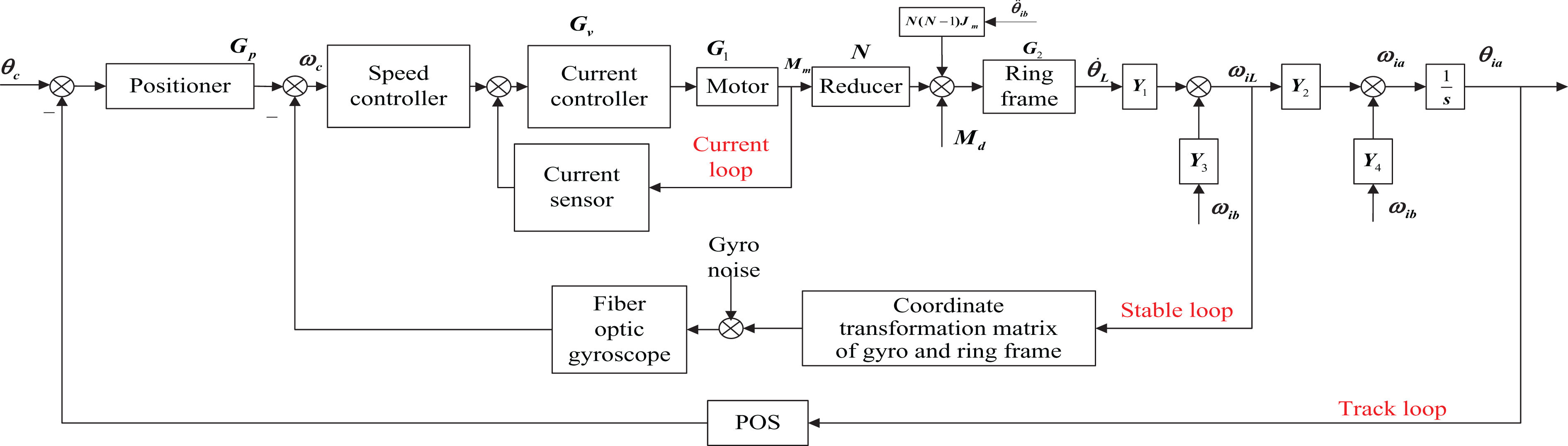
Block diagram of three-loop proportion integration differentiation (PID) control structure of ISP. ISP: inertially stabilized platform.
Dynamic modeling of unbalance
Dynamic modeling
Figure 4 shows the schematic diagram of the functional mechanism of mass imbalance torque under moving base and unmoving base, respectively. The mass imbalance produces LOS jitter when the payload center of gravity is not centered on an axis of rotation for the gimbals. Linear vibration, acting through the lever arm of the center of gravity offset, thus produces torque disturbances. 2 When an ISP is working at a flying aircraft, due to the effects of both gravity acceleration and the motion acceleration of ISP’s gimbals and imaging sensors, the mass imbalance torque occurs.

The geometrically schematic diagram to show the functional mechanism of mass imbalance torque: (a) under moving base condition and (b) under unmoving base condition.
In Figure 2(a),

Then, the disturbance torque of motor is given as

where
In Figure 2(b), gravity component of each axis changes periodically with the change of the angles when the angular position of base changes. The imbalance torque (

The model of the unbalance torque is expressed as

Disturbance torque of motor can be expressed as
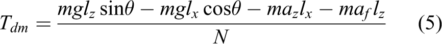
Since the dynamic rotation range of each levelling gimbals is very small, that is, the roll gimbal or pitch gimbal θ is less than 6°, thus equation (3) can be simplified as

Simulation analysis
To analyzing the effect of imbalance torques on control performance, the simulations are carried out. In the simulation, the given parameters are as follows: the suspending mass of roll gimbal is
Figures 5 and 6 show the angular position output simulation results of roll gimbal when the ISP is only influenced by the imbalanced torque disturbance. Figure 5 shows the angular output waveform when the position input is step signal. It can be seen from the figure that if the tracking signal is step signal, the output of the system has an obvious overshoot while the system only works under the effect of imbalanced torque disturbance, and Figure 6 shows the angular output waveform when position input is sinusoidal signal. There are obvious lag and tracking errors in position curve when the system works under the effect of imbalance torque disturbance.

Step input response.

Sinusoidal input response.
Adaptive fuzzy/PID compound controller design
The principle of adaptive fuzzy controller
Fuzzy controller is an intelligent control strategy based on fuzzy mathematics, computer technology, control language rules, fuzzy inference, and decision. 14 The fuzzy controller essentially is a nonlinear controller, whose control algorithm is based on intuition and experience on the plant. Therefore, it does not rely on the precise mathematical model, and it is robust with regard to parameter variations. 18
Figure 7 shows the block diagram of fuzzy control structure. We see that a basic fuzzy control system structure is composed of four main components, namely the knowledge base (KB), the fuzzification interface, the decision logic, and the defuzzification interface. The KB contains knowledge about all the input and output fuzzy partitions. It includes the term set and the corresponding membership functions defining the input variables to the fuzzy “Rule-Base” system and the output or decision variables to the plant. 21

Block diagram of fuzzy control structure.
Adaptive fuzzy/PID compound controller
The adaptive fuzzy/PID controller makes PID parameters self-tuning by calculating input error (e) and change of the error (
The PID regulating law is expressed as

The inputs of the fuzzy controller are the e and

Based on the tests, the initial parameters of PID are determined and the increments of

Adaptive fuzzy/PID controller structure.
The inputs and outputs
For the position loop of each gimbal of ISP, the two input parameters and three output parameters are used in a controller design. Two input parameters are e and
Fuzzification
Fuzzification is an accurate numerical classification, which sets a fuzzy set corresponding to each file. In the design, e,
Selection of subordinating degree function
The membership functions are chosen to represent the inputs in fuzzy set notation. In order to numerically describe an uncertain concept, fuzzy sets proposed by Zadeh (1965) establish a region where some values can still be correctly assigned to it with some possibility degree (Zadeh, 1999). 22,23 The set boundaries that are no longer crisp but fuzzy are defined by a function that assigns a degree of membership to each element when evaluated as a member of the set. 24 Due to the membership function, the system can express all the fuzzy concepts quantitatively. Furthermore, the calculated data will be used in the process of solving the fuzzy relation equation of rule reasoning. Gebell function and Gauss function are chosen in this work. The membership function images of inputs are shown in Figures 9 and 10. Table 1 shows the initial output parameters.
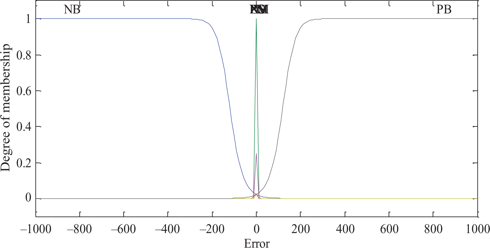
The membership function images of error.

The membership function images of change of the error.
The initial output parameters.

NB: negative big; NM: negative middle; NS: negative small; PS: positive small; PM: positive middle; PB: positive big; ZO: ZERO.
Rule of fuzzy inference
The fuzzy rules are obtained according to the knowledge of experiment to get the better performance of the system. These fuzzy rules can change depending on the type of system characteristics. Properties of PID controller, type of disturbances, system behavior, characteristics of actuator, and gimbals orientation are the impact factors to make these rules. 25 A set of decision rules relating the inputs to outputs are compiled and stored in the memory in the form of a “decision table.” The rules are of the following form 21,26,27 : If (error is NB) and (errorc is NS), then (K p is PB), (K i is PB), and (K d is PB). The decision table is shown in Tables 2 to 4.
Adjustment rule table of

NB: negative big; NM: negative middle; NS: negative small; PS: positive small; PM: positive middle; PB: positive big; ZO: ZERO.
Adjustment rule table of

NB: negative big; NM: negative middle; NS: negative small; PS: positive small; PM: positive middle; PB: positive big; ZO: ZERO.
Adjustment rule table of
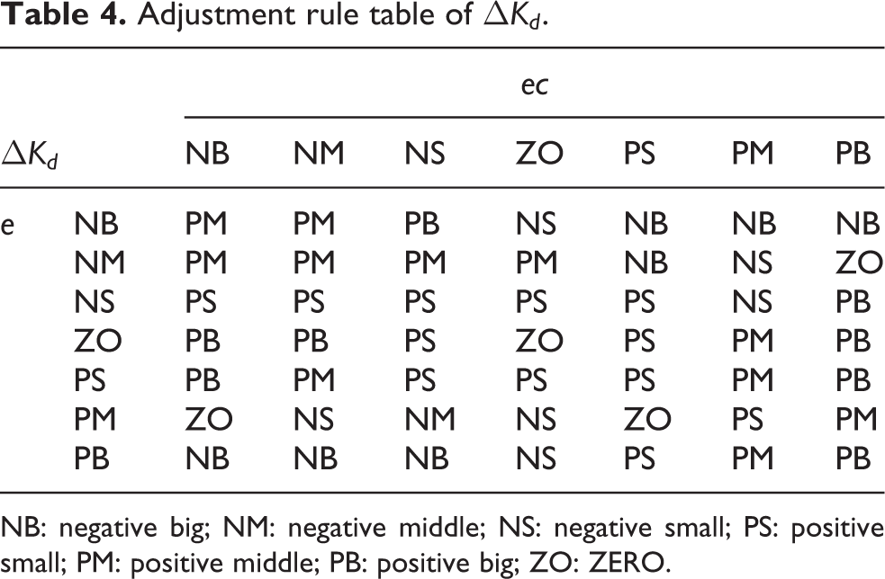
NB: negative big; NM: negative middle; NS: negative small; PS: positive small; PM: positive middle; PB: positive big; ZO: ZERO.
Simulation
In order to verify the performance of the adaptive fuzzy/PID controller, simulations are carried out. As a comparison, the PID controller with fixed parameters is conducted meanwhile. Figure 11 shows the control structure of adaptive fuzzy/PID controller in simulation.

The control structure of adaptive fuzzy/PID controller in simulation.
The main four types of adaptive systems are gain scheduling, model reference adaptive control (MRAC), self-tuning regulators, and dual control. 28 In this article, the MRAC/PID method is compared with the proposed adaptive fuzzy/PID method in simulation analysis to illustrate the effects.
Figure 12 shows the simulation comparisons of sinusoidal input between the adaptive fuzzy/PID controller, MRAC/PID controller, and the PID controller with fixed parameters. While adding the sinusoidal signal into the position system, we can see that the response curve of adaptive fuzzy/PID is almost coincident with the curve of the reference input. But there are very small errors between curve of MRAC/PID and curve of reference input. Comparatively, there are large errors and lag between curve of PID and curve of the reference input.

Simulation comparisons of sinusoidal input between the adaptive fuzzy/PID controller, the MRAC/PID controller, and the PID controller with fixed parameters. MRAC: model reference adaptive control.
Figure 13 shows the simulation comparisons of step input between the adaptive fuzzy/PID controller, the MRAC/PID controller, and the PID controller with fixed parameters. While adding step signal into the position system, we can see that the response time of adaptive fuzzy/PID is 0.6 s. In the meanwhile, the response time of the MRAC/PID is 6.5 s. Comparatively, the response speed and the overshoot of PID controller with fixed parameters are longer and larger, respectively. So, the adaptive fuzzy/PID controller can improve control performance of the system better.
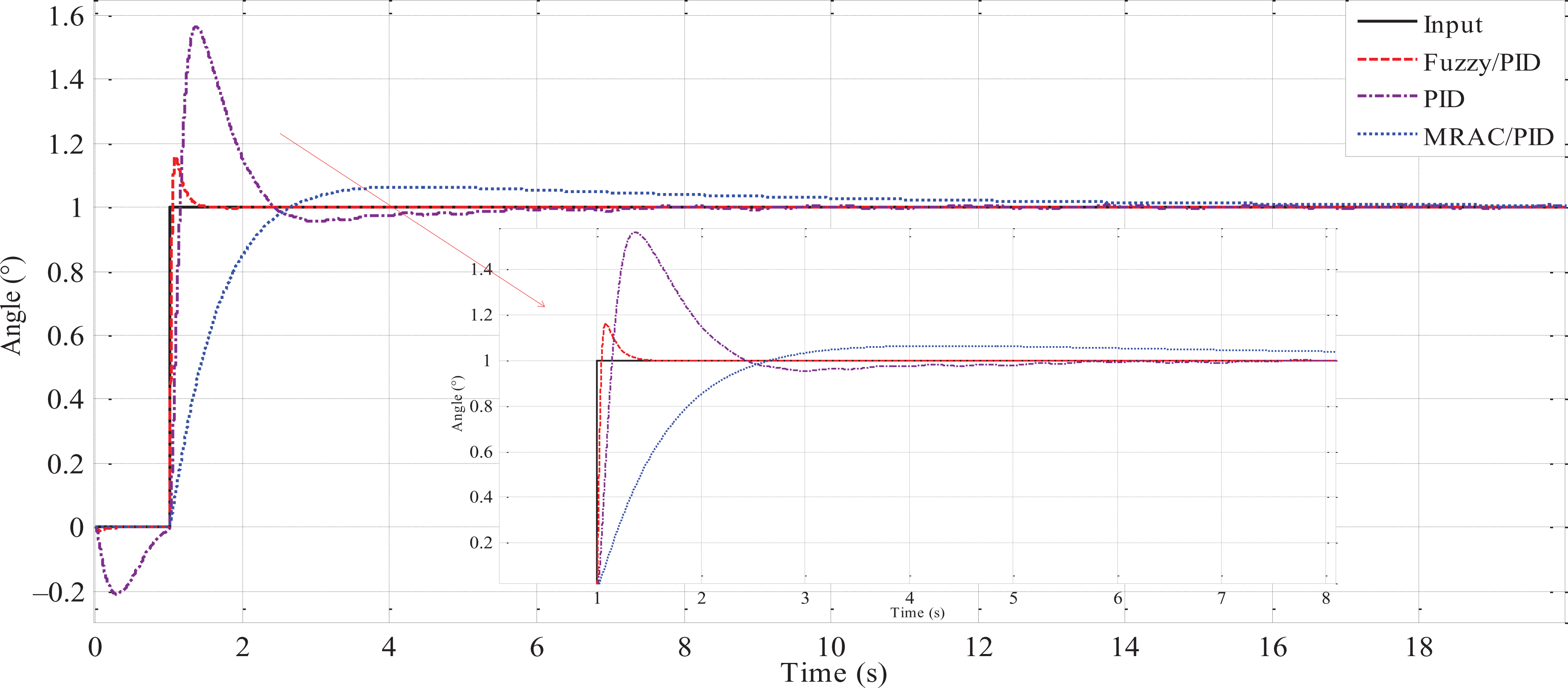
Simulation comparisons of step input between the adaptive fuzzy/PID controller, the MRAC/PID controller, and the PID controller with fixed parameters. MRAC: model reference adaptive control.
Experimental verification
Figure 14 shows the picture of the experimental system. The main physical parameters of the ISP are as follows: maximum load and self-weight are, respectively, 80 kg and 40 kg, the maximum leveling rotation angle range is ±5°, and the maximum heading rotation angle range is ±25°. In experiments, the weight of the artificial load is 30 kg, the power supply voltage is 28 V, and the sampling frequency is 20 Hz. Two different mass blocks are placed on the surface of roll gimbal with 20 cm away from the roll rotation axis, respectively. The weights of two mass blocks are 0.85 kg and 1.65 kg, respectively. Under this circumstance, the mass imbalance torque disturbances to roll rotation axis are 1.7 Nm and 3.3 Nm. As a comparison, the results obtained by PID controller are also displayed.

Performance test of unbalanced torque of the rolling gimbal.
From Figure 15(a), we see that for the case of without mass imbalance torqued disturbance, the root mean square (RMS) errors of roll position for two methods are 0.0117° (PID) and 0.0079° (adaptive fuzzy/PID), respectively. From Figure 15(b), we see that for the case of with mass imbalance torqued disturbance of 1.7 Nm, the RMS errors of roll position for two methods are 0.0136° (PID) and 0.0083° (adaptive fuzzy/PID), respectively. From Figure 15(c), we see that for the case of with mass imbalance torqued disturbance of 3.3 Nm, the RMS errors of roll position for two methods are 0.0161° (PID) and 0.0082° (adaptive fuzzy/PID), respectively.

Experiment comparison between the PID and adaptive fuzzy/PID controllers under three different mass imbalance torque disturbances: (a) 0 Nm, (b) 1.7 Nm, and (c) 3.3 Nm.
Compared with PID, the extents of angular position errors (RMS) obtained by adaptive fuzzy/PID for three cases of imbalance torque disturbances (0 Nm, 1.7 Nm, and 3.3 Nm) are decreased up to 32.5%, 39.0%, and 49.1%, respectively. Obviously, adaptive fuzzy/PID has more excellent dynamically position precision under the conditions of different mass imbalance disturbances.
Conclusion
In this article, an adaptive fuzzy/PID compound control scheme is proposed to deal with the serious influence of predominant unbalance torque disturbance on steady precision of an aerial ISP. The method combining both of the adaptive fuzzy and traditional PID control strategies solved the contradiction between the control precision and robustness on disturbances. In this way, the control parameters of the system are automatically real-time adjusted based on fuzzy adaptive and traditional PID control methods. Thus, the higher dynamic control performance can be obtained. To verify the method, the simulation analysis and experiments are carried out. The experimental results show that compared with PID, the extents of roll position errors (RMS) obtained by adaptive fuzzy/PID under three cases of imbalance torque disturbances (0 Nm, 1.7 Nm, and 3.3 Nm) are decreased up to 32.5%, 39.0%, and 49.1%, respectively, meaning that the adaptive fuzzy/PID compound control scheme has more excellent dynamic performances such as position precision, stability, and disturbances rejection.
Footnotes
Declaration of conflicting interests
The author(s) declared no potential conflicts of interest with respect to the research, authorship, and/or publication of this article.
Funding
The author(s) disclosed receipt of the following financial support for the research, authorship, and/or publication of this article: This work was supported by the National Natural Science Foundation of China (nos. 51375036, 51205019, and 61573040) and the China Scholarship Council.