This paper focuses on the disturbance rejection control problem for inertial stabilization of long-distance laser positioning with the movable platform. Due to various disturbances of the movable platform, the positioning system has significant disturbances that affect the positioning accuracy. Moreover, the nonminimum-phase property of the inertial stabilization system leads to great challenges for designing traditional disturbance-observer-based as well as rejection control methods. In this paper, a dual-compensator disturbance-observer-based control algorithm is proposed to ensure a much stronger rejection of disturbances than those of conventional methods. In particular, it is proven that the two compensators in the proposed method effectively estimate disturbances in different frequency regions. Furthermore, the analytical tuning laws for the proposed dual-compensator disturbance-observer-based control method are presented. The experimental setup including the laser positioning platform demonstrated the validity of the proposed method, which effectively rejected various disturbances.
The long-distance laser positioning (LDLP) system is promising in various fields, such as quantum communication, adaptive optics, large-scale measurement, and long-distance laser communication.1–6 Laser light is used as the carrier of the message or beacon in the systems. The LDLP system plays an important role in long-distance laser communication (LDLC) systems because the high-accuracy inertially stabilized laser is the fundamental component of the high-efficiency LDLC systems. The LDLC systems need to be installed on movable platforms, such as vehicles, ships, airplanes, and satellites. Thus, the LDLC systems can be used in different communication scenarios.7,8 However, the positioning accuracy of the inertially stabilized laser beam in the LDLP system suffers from many serious disturbances, especially when the LDLC systems are installed on movable platforms. The disturbances introduced by movable platforms are mostly located at low and intermediate frequencies, which can significantly affect the stabilization of the tracking systems.9–11
In recent years, the inertial stabilization of the LDLP system is becoming a very popular research field. In the LDLP system, an inertially stabilized platform (ISP) is necessary to reject disturbances with the movable platform.11,12 The position sensor, such as the charge-coupled device (CCD), can detect the position errors between the target position and the pointing position of the laser. With the CCD, the position feedback control (PFC) loop of the ISP provides the tracking capability to aim at a far-away target position. However, the CCD requires sufficient integration time to obtain an image with a high signal-to-noise ratio (SNR). Thus, the CCD has a limited low sampling rate.13 As a result, the low sampling rate of the CCD limits the closed-loop bandwidth and disturbance rejection performance of the PFC loop according to the Nyquist Sampling Theorem.14 Consequently, the disturbances are difficult to reject with the conventional PFC loop in the LDLP system.11
To reject more disturbances, new control methods have been introduced into the LDLP systems. The inertial sensors operate at higher sampling rates, which can update at 5 kHz. Thus, the micro-electro-mechanical system (MEMS) accelerometers and the fiber optical gyroscopes (FOGs) can be used to obtain high-bandwidth closed loops.15–17 Thus, a multi-loop feedback control (MFC) system with MEMS accelerometers, FOGs, and a CCD has been proposed.18,19 The MFC system is composed of an acceleration feedback control (AFC) loop, a velocity feedback control (VFC) loop, and a PFC loop. In the MFC system, the bandwidth of the inner loop is significantly higher than that of the outer loop. The disturbance rejection capability of the MFC system is the product of each loop, so the MFC system can reject more disturbances than the PFC system.
The direct disturbance feedforward method based on measurements is also recommended to reject the external disturbances in theory.20,21 However, it requires additional costs for the extra sensors and achieves limited performances in actual environments. In the 1980s, the disturbance-observer-based control (DOBC) method was presented by Ohnishi to suppress the estimated disturbances, which avoided the application limitations and extra costs.22,23 The DOBC method has been applied to various engineering processes, such as fluidized bed combustor, mobile robots, chain driving system, and networked dynamic system.24–27 To remove the impact of mismatched uncertainty from the output with the DOBC method, the systematic disturbance compensation gain design method and the sliding-mode control method were introduced.28,29 Based on the DOBC method, the repetitive controller and reduced-order observer were presented to deal with the slow dynamics system.30–32 Besides, the internal uncertainty and external disturbances of the linear system can be estimated by an extended state observer using an active disturbance rejection control method.33–36 The nonlinear DOBC and equivalent-input-disturbance approach were developed to deal with uncertainty in nonlinear dynamics, which improved the robustness of the system.37,38 In the LDLP system, the ISP is a typical linear time-invariant system. However, the IPS has the nonminimum-phase property in the inertially closed loop, which can make the DOBC system unstable. To avoid instability, the DOBC method was used in the PFC loop to control the ISP, because there is no nonminimum-phase property in the PFC loop. However, the disturbance rejection performance of the DOBC was limited by the low bandwidth of the PFC loop. Unlike the CCD, the MEMS accelerometer has a low weight, small size, and high sampling rate. Therefore, the DOBC method was utilized in the inertial AFC loop, which has a much higher bandwidth than the PFC loop.39 The AFC loop with a higher bandwidth was beneficial for rejecting more disturbances over a wider frequency range. However, there was a nonminimum-phase property of the AFC loop, and the DOBC method was limited by the causality and stability restrictions of the system. To stabilize the system, the DOBC method sacrificed the disturbance rejection capability, which could only reject the disturbances in the intermediate-frequency band.40 Thus, the DOBC method is utilized in the AFC loop and the PFC loop to reject more disturbances.41 However, it is still the simple applications of the DOBC method, which has no contribution to modify it. The high-frequency disturbances could be passively rejected by the mechanical structure of the ISP.40,42 Thus, the disturbances in the low- and intermediate-frequency bands vastly decreased the positioning accuracy of the optical path.43 However, the previous methods had insufficient disturbance rejection capabilities in the low- and intermediate-frequency bands. Therefore, ensuring the high-accuracy inertial stabilization of the ISP with a nonminimum-phase property is still a challenge, which requires a better disturbance rejection method.
In this paper, we propose a dual-compensator disturbance-observer-based control (DC-DOBC) algorithm, which can be plugged into an existing inertial feedback loop. The DC-DOBC method is introduced into the LDLP system to reject disturbances and improve the positioning accuracy of the laser light. The main contributions are as follows:
The DC-DOBC structure is proposed to reject the disturbances of the ISP control system, which has a nonminimum-phase property. An additional compensator is introduced to the DC-DOBC structure for the first time. The disturbances are first estimated and rejected once by the additional compensator, after which the original compensator estimates and rejects the residual disturbances once again. Thus, the disturbance estimation and suppression capabilities of the system are composed of those of the dual compensators in the DC-DOBC method.
Although there is still a nonminimum-phase property in the ISP control system, both compensators in the DC-DOBC method have different stability restrictions and disturbance estimation capabilities in this paper. Based on these, the analytical tuning laws for the proposed dual compensators are presented. Compared with the most recent methods, one distinct novelty in the DC-DOBC method is that the analytical tuning of the additional compensator offers an extra capability to estimate and reject more disturbances.
In the DC-DOBC method, the additional compensator exhibits better disturbance estimation and suppression capabilities than the original compensator in the low-frequency band. Therefore, in the LDLP system, the dual compensators can reject the disturbances in different frequency bands simultaneously. The DC-DOBC method can reject more disturbances of the ISP control system over a wider frequency range than the conventional DOBC method. The experimental setup with a laser positioning platform driven by voice-coil motors demonstrated the effectiveness of the proposed method in the presence of various disturbances.
The rest of the paper is organized as follows. In section “DC-DOBC structure,” the new control structure of the DC-DOBC method is introduced. In section “Stability analysis,” the stability restriction is discussed. In section “Disturbance estimation and suppression analysis,” the analytical tuning laws of the dual compensators are presented. In section “Experiments,” experiments to validate the proposed method are described. Finally, concluding remarks are presented in section “Conclusion.”
DC-DOBC structure
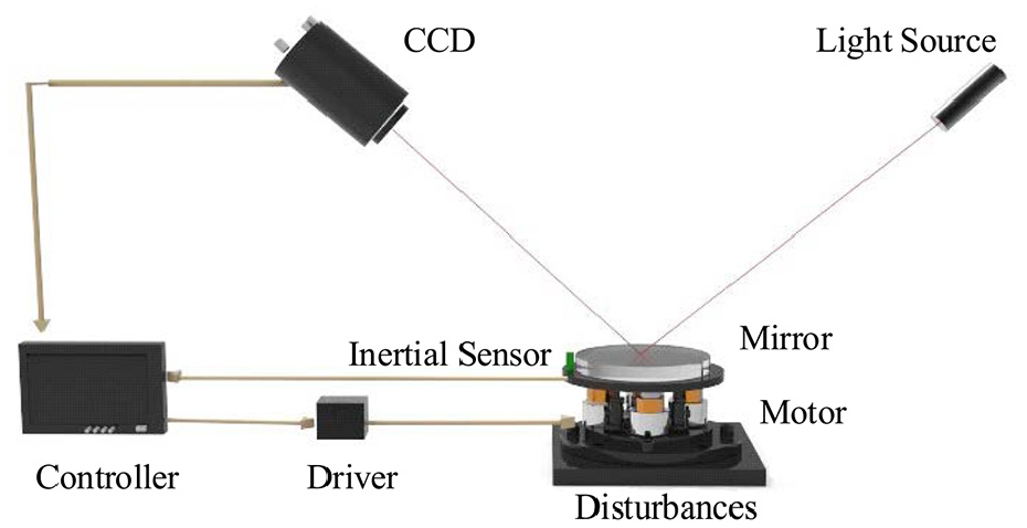
A typical LDLP system can be used to stabilize the laser beam in the inertial space, which is convenient for the LDLC programs.3,12 However, the optical path suffers from disturbances when the LDLP system is installed on movable platforms, such as ships and satellites. Thus, the ISP shown in Figure 1 is indispensable in the LDLP system. The ISP is driven by voice-coil motors to reflect the laser, and thus, it can be used to stabilize the optical path. The CCD provides position errors between the target and pointing positions of the laser to control the ISP. To obtain a higher positioning accuracy, it is crucial to reject the disturbances transmitted from the pedestal.
Diagram of the inertially stabilized platform control system.
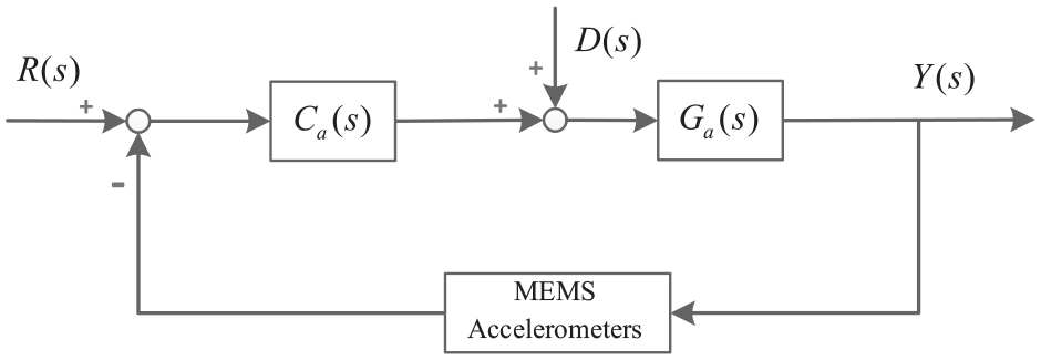
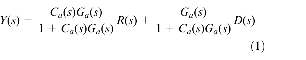
When the LDLP system operates on a movable platform, the MFC method is usually used as a primary control structure to stabilize the optical path in inertial space. In the MFC system, the AFC loop has the highest bandwidth. The feedback closed loop with a higher bandwidth is beneficial for rejecting more disturbances over a wider frequency range. Therefore, the AFC loop with MEMS accelerometers is an important part of the LDLP system, which is shown in Figure 2. In this figure, is the given acceleration input, is the external acceleration disturbances, is the acceleration output, is the acceleration controller, and is a combination of the electronic equipment and the characteristics of the mechanics of the ISP in the AFC loop.
Acceleration closed-loop with the MEMS accelerometers.
The transfer function of Figure 2 is expressed as follows
From equation (1), the disturbance transfer function depends on the controller in the AFC loop. A high gain of the controller benefits the bandwidth and disturbance rejection capability. However, the high gain of the controller reduces the stability margin of the system. Although there is a high-sampling-rate MEMS accelerometer, the bandwidth and disturbance rejection capability of the AFC loop is restricted by the mechanical resonance and the driving capability of the actuators. The MFC method is insufficient for rejecting the disturbances.
To improve the disturbance rejection capability, the conventional DOBC methods can be utilized in the AFC loop as shown in Figure 3. In this figure, is a filter that can feed-forward the estimated disturbances, and is the inverse of the nominal plant of the ISP.
Conventional DOBC method in the AFC loop.
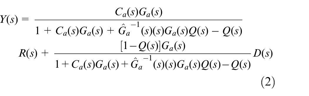
Based on Figure 3, the system transfer function is depicted as follows
The external disturbances, which are estimated by the filter , can be rejected by the DOBC method. In the DOBC method, the inverse of the nominal plant is always necessary. However, the nominal plant includes the critical stable zeros in the AFC loop, which compose the nonminimum-phase property. Thus, the ideal with unstable poles can lead to system instability. To avoid instability, the nonminimum-phase property is artificially replaced by the minimal-phase property. As a result, the altered cannot transfer the disturbances over the whole frequency band to the filter . Furthermore, the tracking transfer characteristics of the system can also vary, which would be different from that of the AFC loop. Thus, the DOBC method in the AFC loop can alter the stability and tracking capability of the system. To guarantee system stability, the DOBC method usually sacrifices a lot of the disturbance rejection capabilities. According to the previous report,40 when the DOBC method is used to control the ISP with a nonminimum-phase property, it can only improve the disturbance rejection capability in the intermediate-frequency band.
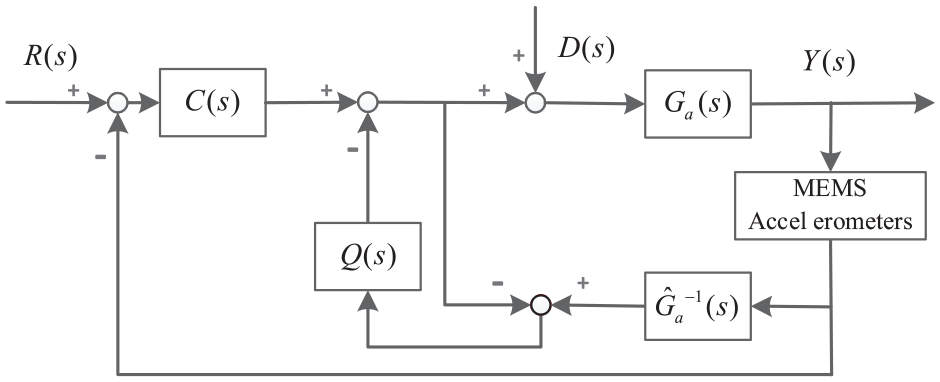
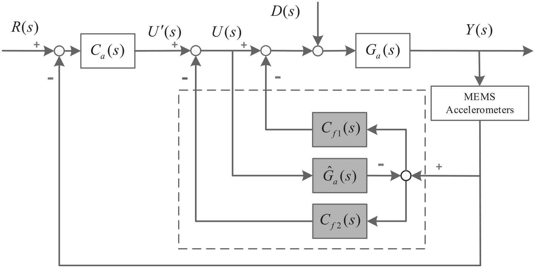
To overcome the shortcomings of the DOBC method and reject more disturbances, we propose the DC-DOBC method shown in Figure 4. In this figure, is the nominal plant of the ISP in the AFC loop. is the output of the acceleration controller, and is the input of the nominal plant . is the compensator of the inner disturbance estimation loop, and is the compensator of the outer disturbance estimation loop.
Proposed dual-compensator disturbance-observer-based control (DC-DOBC) structure.
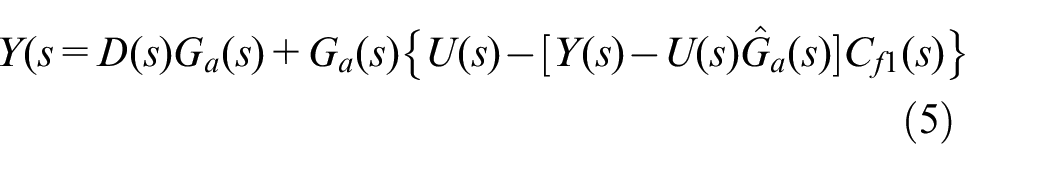
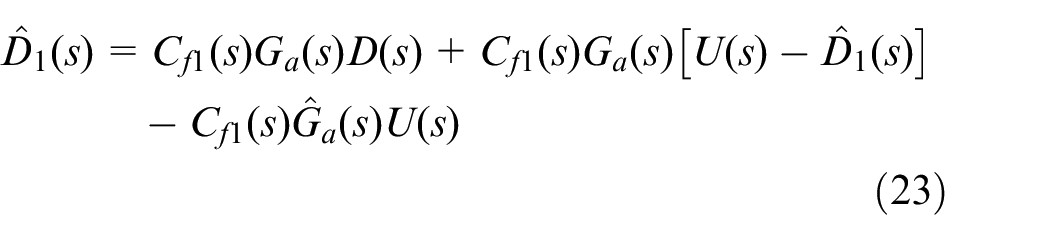
To avoid an unstable , which has unstable poles, we use the nominal plant in its place. Although the nominal plant has a nonminimum-phase property, its poles are all stable. Therefore, the nominal plant can describe the linear ISP accurately. The compensator is used to estimate the disturbances, which is similar to the filter in the DOBC method. Therefore, if compensator in the DC-DOBC method, the system will have similar performances to those of the DOBC method. Thus, compensator is still limited by the stability restriction, and it can only estimate and reject the disturbances in the extremely finite frequency range. To reject more disturbances, using the proposed DC-DOBC method, we added an extra compensator in the inner loop. The compensator can also estimate the disturbances, but its performance is completely different from that of the compensator . The additional compensator offers an extra capability to estimate the disturbances in a different frequency range, because its stability restriction and disturbance estimation capability are different from those of the compensator . The disturbances are first estimated and rejected once by compensator , after which the compensator estimates and rejects the residual disturbances once again. As a result, the DC-DOBC method can reject more disturbances over a wider frequency range in the LDLP system. To analyze the DC-DOBC method quantitatively, the following equations are based on Figure 4
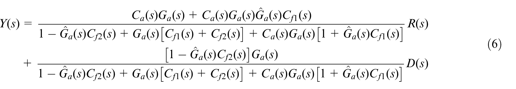
When the DC-DOBC method is utilized in the AFC loop, the transfer function of the system can be expressed as follows after substitution
Stability analysis
The system stability restricts the control performance of the DC-DOBC method. According to equation (6), the tracking transfer function of the system with the DC-DOBC method in the AFC loop can be depicted as follows
The bandwidth of the MEMS accelerometer is much higher than the bandwidth of the AFC loop, so the high-accuracy nominal plant of the ISP control system can be acquired through system identification.44,45 However, there is still internal uncertainty of the ISP, which is caused by the parameters or unmodeled dynamics. The internal uncertainty can be expressed as .
Lemma 1
If the compensators and satisfy the following conditions
then the tracking transfer function (equation) is stable.
Proof
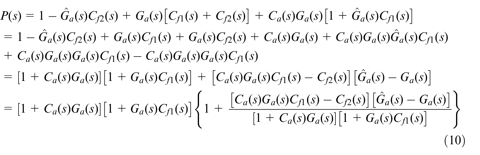
According to the tracking transfer function of the system with the DC-DOBC method in equation (7), its denominator is denoted as , which is expressed as follows
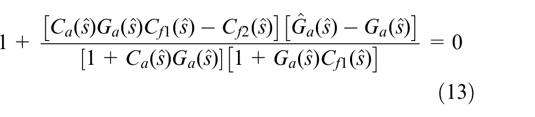
If is a pole of the tracking transfer function , there will be a characteristic polynomial . At least one of the following three conditions is satisfied when
Based on equation (10), the transfer function is defined as follows
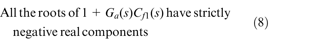
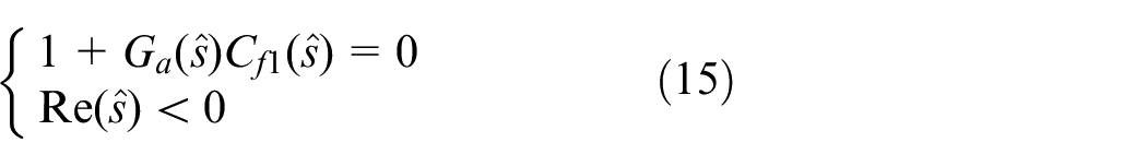
The roots of compose a part of the poles of the tracking transfer function . To analyze the stability of , which is related to and , we can analyze the roots of first. Because is the characteristic polynomial of the original AFC loop, the roots of all have strictly negative real components. Therefore, if satisfies
then the roots of have strictly negative real components. If so, the compensator satisfies the stability restriction.
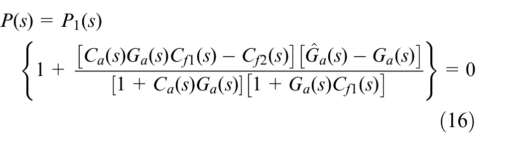
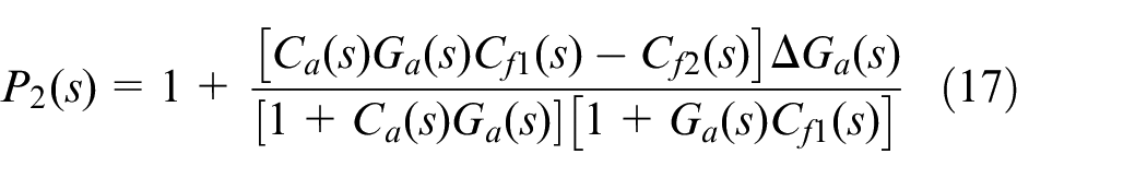
After is constrained as equation (15), the characteristic polynomial can be expressed as follows
There is internal uncertainty of the ISP, which can be expressed as . The transfer function is defined as follows
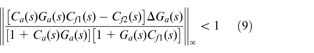
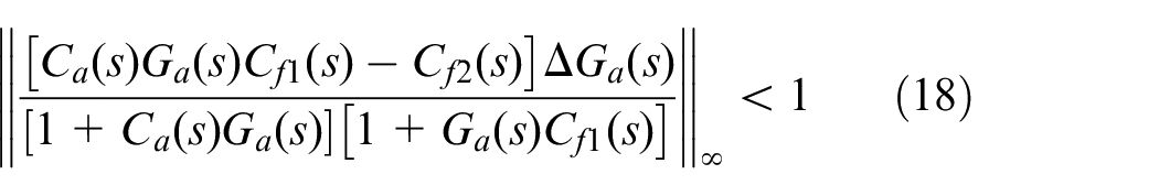
It is too complicated to calculate all the roots of to analyze the stability restriction of compensator . Thus, a much stronger restriction is used to guarantee the stability of the DC-DOBC method. According to the small gain theory,39 the stability restriction of the tracking transfer function can be depicted as follows
Therefore, if the compensators and satisfy equations (15) and (18), the tracking transfer function given in equation (7) is stable. Thus, the proof is complete. □
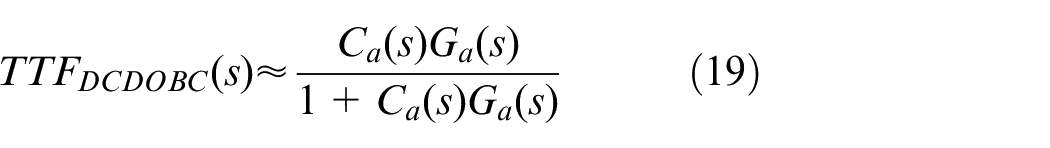
If the stability restrictions in Lemma 1 are satisfied, the tracking transfer function of the system can be expressed as equation (19). Compared with equation (1), the DC-DOBC method has little influence on the tracking performance of the system based on the stability restrictions
When the DC-DOBC method is introduced to the system, the system stability can be guaranteed by Lemma 1. The dual compensators and have different stability restrictions. Based on Lemma 1, the dual compensators in the DC-DOBC method can be designed to estimate and reject the disturbances.
Disturbance estimation and suppression analysis
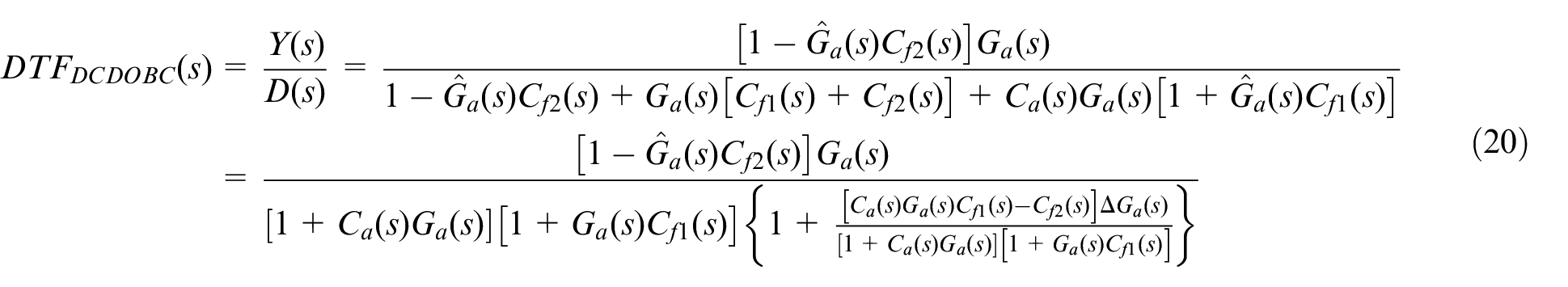
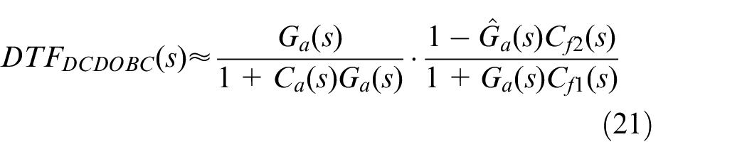
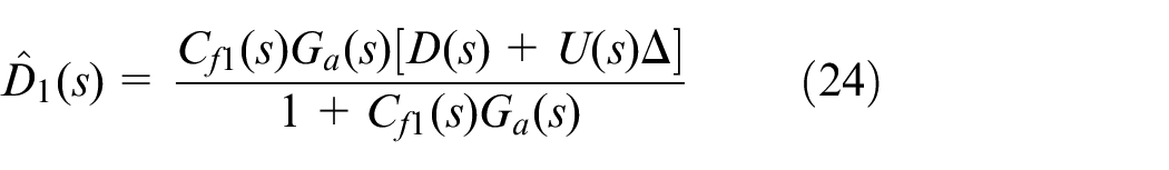
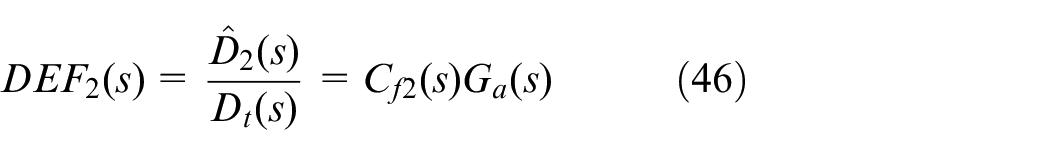
According to equation (6), the disturbance transfer function of the AFC loop with the DC-DOBC method can be depicted as follows
When the DC-DOBC method satisfies the stability restrictions, equation (18) can be obtained according to Lemma 1 in section “Stability analysis.” Therefore, the disturbance transfer function can be expressed as follows
By comparing equations (1) and (21), it is evident that the disturbance rejection capability of the system can be, respectively, improved by and in the DC-DOBC method. Thus, the compensator can first reject the disturbances once, after which the residual disturbances are rejected by the compensator once again. The DC-DOBC method can reject the disturbances simultaneously with the dual compensators.
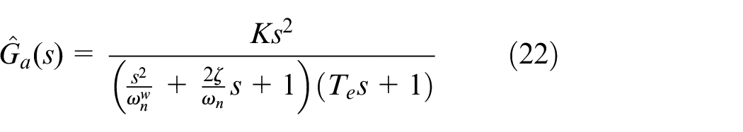
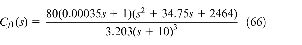
In the LDLP system, the inertial sensors are indispensable. Because the MEMS accelerometer has a low weight, small size, and high sampling rate, the high-bandwidth AFC loop plays an important role in the LDLP system. The AFC loop with higher bandwidth is beneficial for rejecting more disturbances over a wider frequency range. Therefore, the DC-DOBC method is essential to be used in the high-bandwidth AFC loop. In the AFC loop, the nominal plant of the controlled object is shown as follows
By utilizing the electrical analysis and the system identification, the parameters of the nominal plant can be concretely identified.44,45 In the nominal plant , and are the parameters of the resonance element. and denote the parameter of the inertial element and the proportional constant.
A feature of the nominal plant in the AFC loop is that it includes the critical stable zeros shown in equation (22), which compose the nonminimum-phase property. The nonminimum-phase property limits the control performance of the DOBC in the AFC loop. The filter of the DOBC can only estimate and reject the disturbances in the intermediate-frequency band, which is limited by the stability restriction.40 Although the nominal plant still has a nonminimum-phase property in the DC-DOBC method, and have different stability restrictions. The dual compensators also have different disturbance transfer functions according to equation (21). Therefore, it is important to estimate and reject the disturbances with the different compensators in the DC-DOBC method.
Disturbance estimation of compensator
The compensator can be used to estimate and suppress the disturbances, as shown in Figure 4. The disturbance estimated by compensator is denoted as . According to Figure 4, the estimated disturbance can be expressed as follows
where is the input of the nominal plant , and represents the external disturbances. The estimated disturbance is shown as follows
where is the internal uncertainty of the ISP, which is caused by the parameters or unmodeled dynamics.
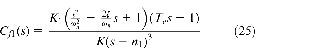
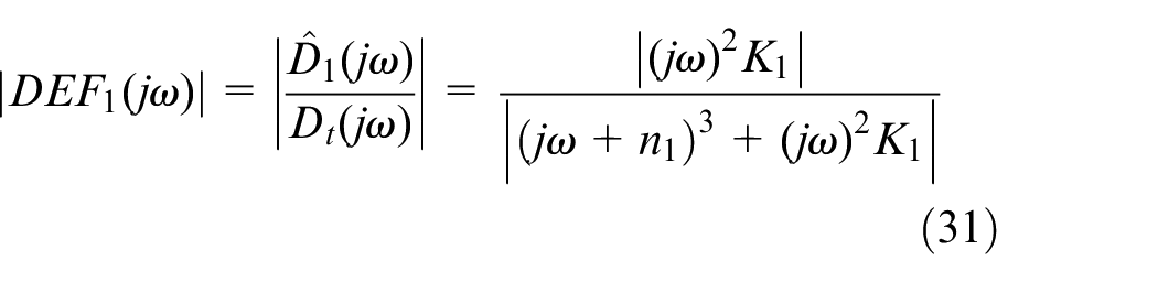
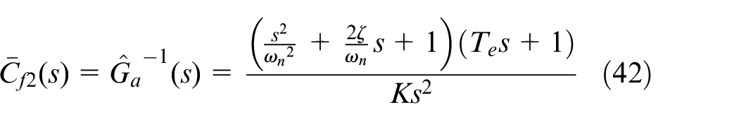
Because represents the external disturbances, the “total disturbances” can be expressed as . To reject the disturbances, the compensator should be used to estimate the “total disturbances”. Although there is a nonminimum-phase property in the nominal plant , the compensator can be designed according to Lemma 1 as follows
where and are the constant parameters.
Theorem 1
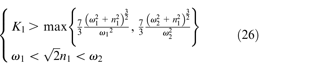
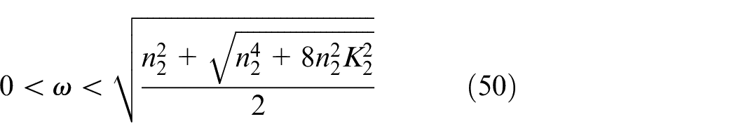
For any given strictly positive parameters and , where , if and are designed to satisfy
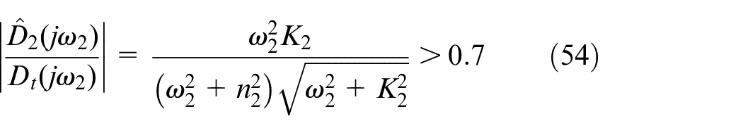
then the transfer function from “total disturbances” to estimated disturbances satisfies the following
Remark 1
Theorem 1 shows that the compensator can recover the “total disturbances” in the given frequency region by tuning and selecting a sufficiently large to satisfy equation (26). More importantly, equation (26) quantitatively presents the tuning law for and . It is also evident that equation (26) can be achieved by designing a sufficiently small and sufficiently large .
Proof
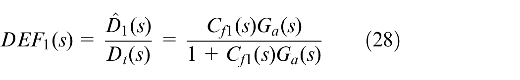
According to equation (24), the disturbance estimation function relating “total disturbances” to estimated disturbances is expressed as follows
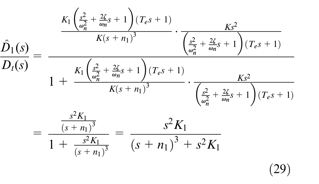
The compensator is designed as equation (25), which results in the following equation
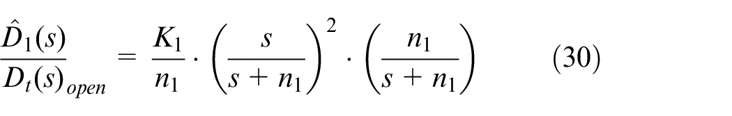
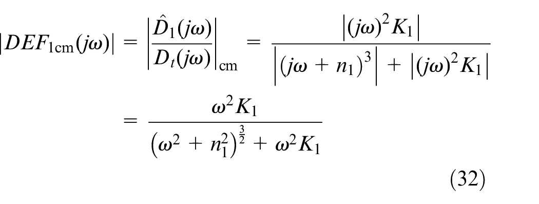
According to equation (29), it is a unit negative feedback loop of the open-loop transfer function shown in equation (30) which is a band-pass filter. Therefore, the disturbance estimation function works as a band-pass filter
The amplitude–frequency characteristics of the disturbance estimation function is shown as follows
There is another amplitude–frequency characteristics of transfer function , which is defined as follows
Thus, the amplitude–frequency characteristics of and satisfy the inequality
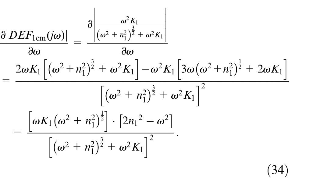
By taking a derivative with respect to frequency of , the following equation is derived
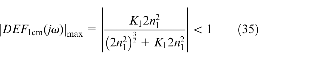
Therefore, for , and for . Thus, when , monotonously increases, and when , monotonously decreases. The maximum value of can be expressed as follows
When , . If the following inequation is satisfied
then the following equation can be obtained
When , . If the following inequation is satisfied
then the following equation can be obtained
As a result, for any given strictly positive parameters and , where , if and are designed to satisfy equation (26), the transfer function relating to satisfies equation (27). Thus, the proof is complete. □
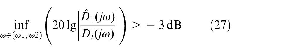
According to Theorem 1, the compensator can be used to estimate and recover the disturbances in the specific frequency band, because the amplitude attenuation of is less than −3 dB in this frequency band. Thus, the disturbances can be estimated and rejected by the compensator . The disturbance rejection capability can be improved by the compensator in the DC-DOBC method.
Disturbance estimation of compensator
According to Figure 4, the disturbances can also be estimated and suppressed by the compensator in the DC-DOBC method. The disturbance estimated by the compensator is depicted as , which is expressed as follows
where is the input of the nominal plant , and denotes the external disturbances. The estimated disturbance is expressed as follows
where is the internal uncertainty of the ISP.
Based on equation (41), the ideal compensator can be expressed as follows
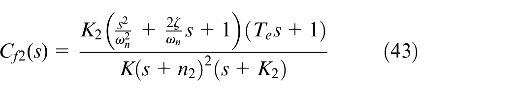
However, the nonminimum-phase property of the nominal plant introduces unstable poles to the ideal compensator , which leads to system instability. To suppress the “total disturbances,” the compensator is designed in the DC-DOBC method based on Lemma 1, as follows
where and are the constant parameters.
Theorem 2
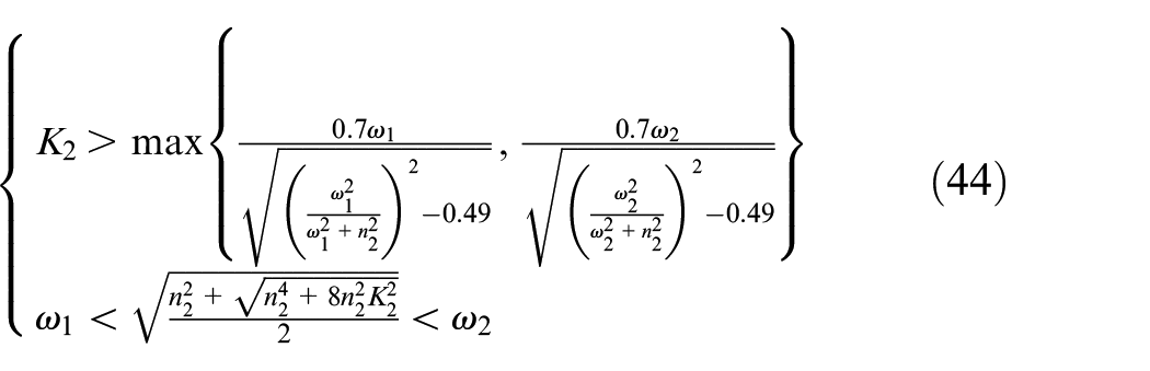
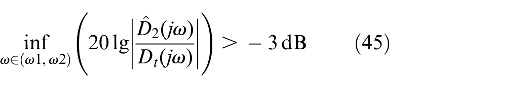
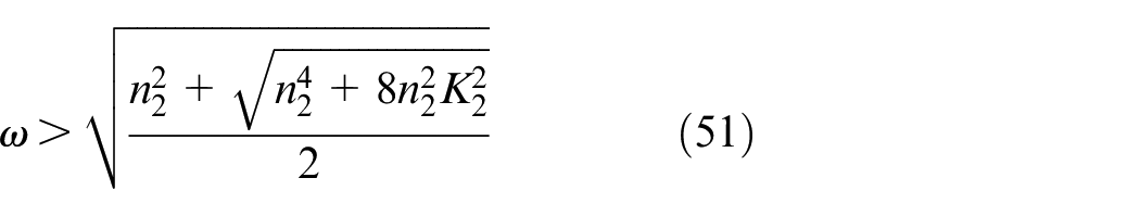
For any given strictly positive parameters and , where , if and are designed to satisfy
then the transfer function relating “total disturbances” to estimated disturbances satisfies the following
Remark 2
Theorem 2 shows that the compensator can recover the “total disturbances” at the given frequency region by tuning and selecting a sufficiently large to satisfy equation (44). More importantly, equation (44) quantitatively presents the tuning law for and . It is also evident that equation (44) can be achieved by designing a sufficiently small and sufficiently large .
Proof
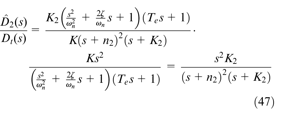
Based on equation (41), the disturbance estimation function from to is expressed as follows
The compensator is designed as equation (43), resulting in the following equation
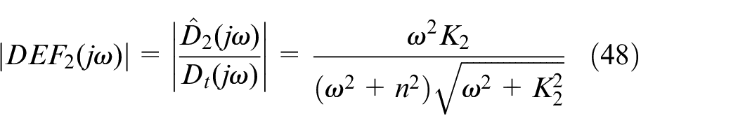
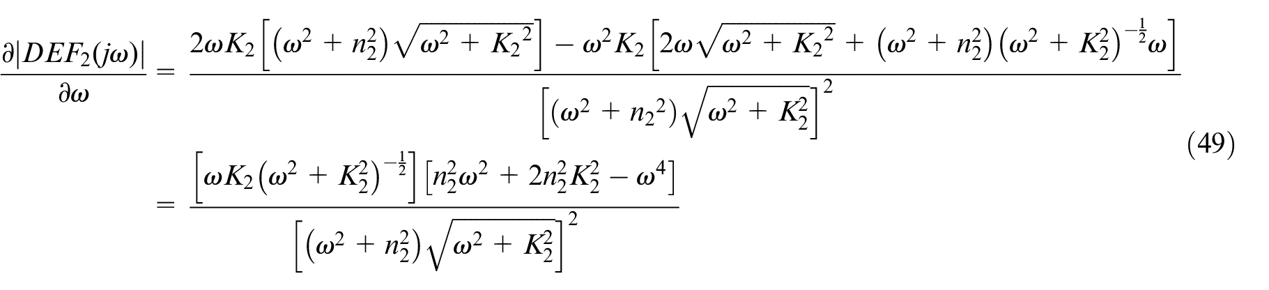
To analyze the disturbance estimation performance of the compensator , the amplitude–frequency characteristics of are shown as follows
Taking a derivative of with respect to frequency yields the following
Therefore, when satisfies
monotonously increases. When satisfies
monotonously decreases.
As a result, when satisfies equation (50) and , . If
As a result, for any given strictly positive parameters and , where , if and are designed to satisfy equation (44), then the transfer function relating to satisfies equation (45). Thus, the proof is complete. □
According to Theorem 2, in the specific frequency band, compensator can be used to estimate and reject the disturbances because the amplitude attenuation of is less than −3 dB in the specific frequency band. Therefore, the disturbance rejection capability can be improved by the compensator with the DC-DOBC method. In the DC-DOBC method, the compensator can first reject the disturbances once, after which the residual disturbances are rejected by the compensator once again. Therefore, compensators and can operate simultaneously to reject the disturbances. Although compensators and in the DC-DOBC method can be used to reject the disturbances, they also have differences.
Theorem 3
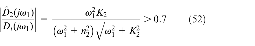
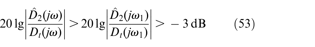
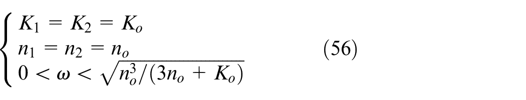
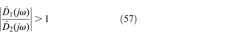
For any given strictly positive parameters and , where , if , , , and are designed to satisfy
then the transfer function from to satisfies
Remark 3
Theorem 3 shows that compensators and can recover the “total disturbances” by tuning and . More importantly, in the low-frequency band, the compensator exhibits a better disturbance estimation performance than the compensator .
Proof
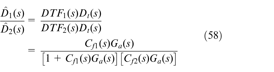
Based on the disturbance estimation functions and given by equations (28) and (46), the transfer function from to can be expressed as follows
When the parameters in the compensators and satisfy , the following expression is obtained
Because , . Therefore
By defining as follows
it is evident that the imaginary components of the denominator and numerator in are the same.
If , then
As a result, the following inequality can be obtained when
Thus, for any given strictly positive parameters and , where , if , , , and are designed to satisfy equation (56), the transfer function from to satisfies equation (57). Thus, the proof is complete. □
According to Theorem 3, the compensator exhibits a better disturbance estimation performance than the compensator in the low-frequency band. Thus, the disturbances in the low-frequency band can be better rejected by the compensator rather than the compensator . Furthermore, in the DC-DOBC method, compensators and can work together to estimate and reject the disturbances. As a result, the DC-DOBC method with dual compensators can estimate and reject the disturbances in different frequency bands simultaneously. Compared with the DOBC method, the DC-DOBC method can reject more disturbances over a wider frequency range.
Experiments
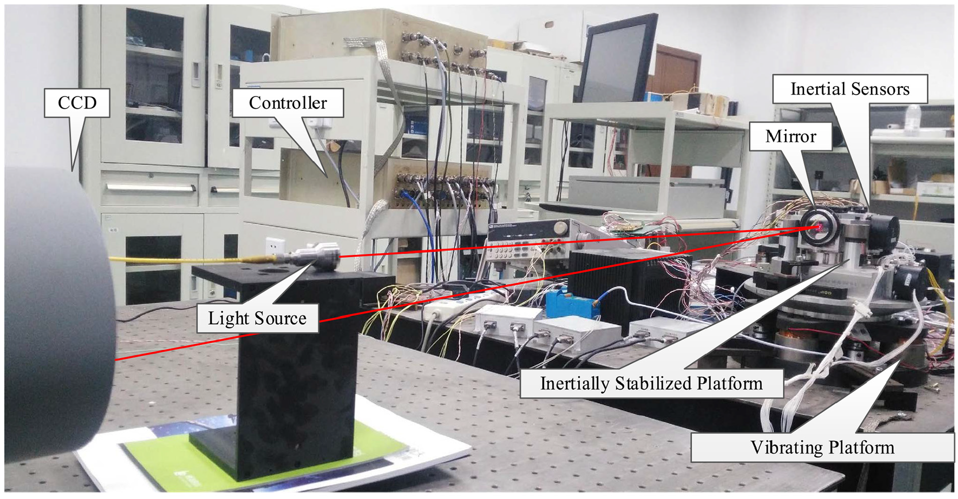
To verify the analyses above, we constructed an experimental setup of the ISP control system, as shown in Figure 5. The laser light was reflected from the rotating mirror to the image sensor CCD. The rotating mirror was mounted on the ISP that was driven by the voice-coil motors. A vibrating platform was mounted under the ISP. The vibrating platform driven by the voice-coil motors was used to emulate the external disturbances in actual environments. The CCD operated with a 100-Hz sampling rate with a two-frame time delay. Because the actual LDLP system requires two-frame time to process each frame image. The CCD outputs the position errors between the laser light and the center point of the image panel. The inertial sensors, including the MEMS accelerometers and the FOGs, were installed on the ISP, and they updated data at a rate of 5 kHz. We focused on one axis due to the symmetry of the platforms. The control unit included a digital signal processor (DSP), analog-to-digital converters (A/D), digital-to-analog converters (D/A), power driving amplification, and field programmable gate array (FPGA). The DSP used signals from sensors to implement a controller to activate the power driving amplification to control the ISP.
Experimental devices.
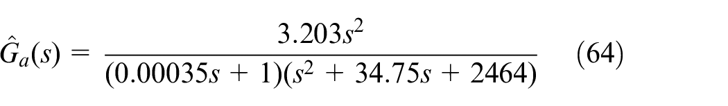
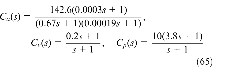
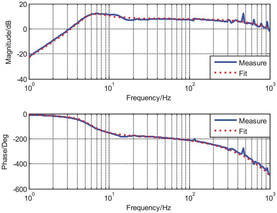
The open-loop acceleration response of the ISP control system is shown in Figure 6, which was obtained by the system identification with the MEMS accelerometer. The nominal plant of the acceleration open-loop object is depicted in equation (64). We can use the proportional–integral (PI) or proportional–integral–derivative (PID) control method to design the controllers of the AFC, VFC, and PFC loops of the MFC method. The MFC controllers are expressed in equation (65)
Open-loop characteristic acceleration response of the ISP.
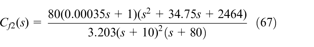
According to previous analysis in section “Disturbance estimation and suppression analysis,” compensators and of the DC-DOBC method have different capabilities to estimate the disturbances. To examine the differences between compensators, and are designed as follows
where .
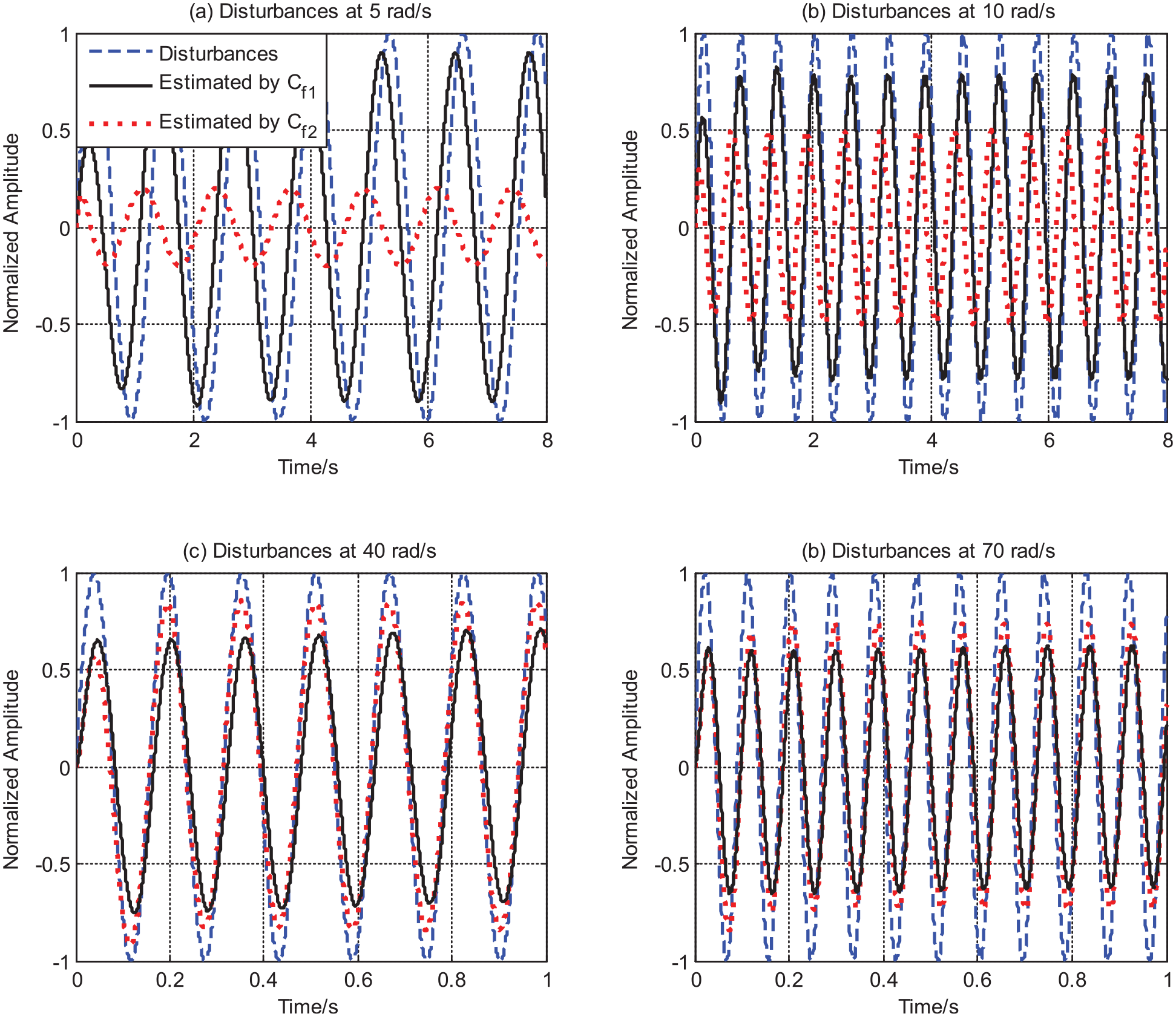
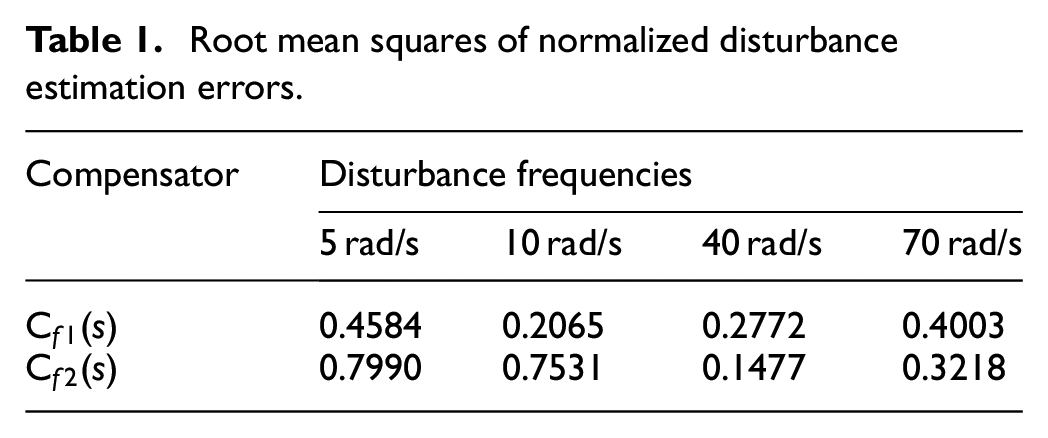
Compensators and are, respectively, used to estimate the disturbances in different frequencies. Therefore, the frequencies of the disturbances are set to 5, 10, 40, and 70 rad/s. The simulated results are shown in Figure 7. In this figure, the amplitudes of the disturbances are normalized. According to the results, the disturbances at 5 and 10 rad/s could be much better estimated by the compensator rather than the compensator . The disturbances at 40 and 70 rad/s could be better estimated by the compensator . The root mean squares (RMSs) of disturbance estimation errors are compared in Table 1. It is clear that the compensator has much smaller estimation errors than in the low-frequency band. And the compensator has smaller estimation errors than in the intermediate-frequency band. Therefore, compensators and of the DC-DOBC method had different capabilities to estimate the disturbances in different frequency bands. In fact, the compensator in the DC-DOBC method is similar to the filter in the DOBC method when the compensator . However, unlike the DOBC method, the DC-DOBC method has additional compensators , so the proposed method has the capability to estimate additional disturbances in the low-frequency band. Therefore, the outstanding disturbance estimation range of the DC-DOBC method allows it to reject more disturbances over a wider frequency band.
Simulated disturbance estimation performances of the compensators in the DC-DOBC method.
Root mean squares of normalized disturbance estimation errors.
Compensator
Disturbance frequencies
5 rad/s
10 rad/s
40 rad/s
70 rad/s
0.4584
0.2065
0.2772
0.4003
0.7990
0.7531
0.1477
0.3218
After verifying the different disturbance estimation capabilities of compensators and , we took advantage of both compensators using different parameters. The compensator was mainly designed to reject the disturbances in the low-frequency band, which was expressed as follows
Different from it, the compensator was designed to reject the disturbances in the intermediate-frequency band mainly, which was expressed as follows
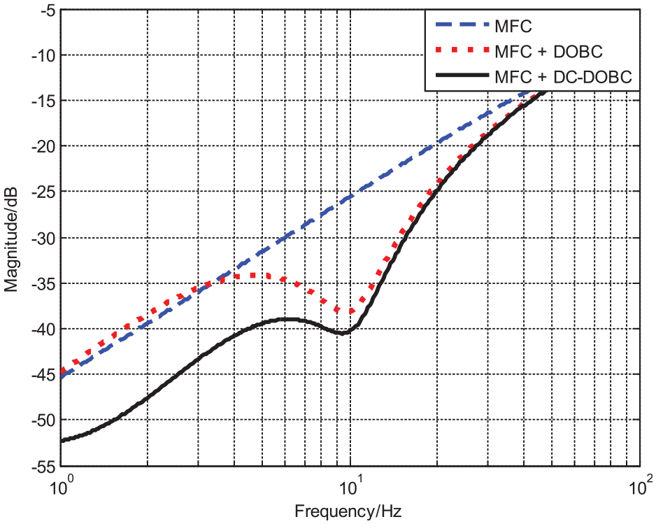
The simulated disturbance rejection capability of the system with the DC-DOBC method is shown in Figure 8. Before the simulated testing, the MFC system was built with experimental devices. The CCD, the FOGs, and the MEMS accelerometers were used as sensors to build the MFC system, which is composed of the PFC loop, the VFC loop, and the AFC loop. Then, the parameters of feedback controllers in the MFC system were used to build the simulated MFC system with MATLAB Simulink. Based on the simulated MFC system, DOBC and DC-DOBC methods were introduced to simulate disturbance rejection capabilities. According to the previous analysis, the filter of the DOBC method plays the same role as the compensator of the DC-DOBC method. Therefore, we used the compensator defined in equation (69) when compensator to represent the DOBC method. To compare with it, the DC-DOBC method, whose dual compensators were defined in equations (68) and (69), was also introduced into the simulated MFC system. As shown in Figure 8, the DOBC method exhibited a similar disturbance rejection performance to the DC-DOBC method in the intermediate-frequency band. However, the DC-DOBC method with additional compensator had extra disturbance rejection capability in the low-frequency band. Therefore, more disturbances could be rejected over a wider frequency range due to the dual compensators in the DC-DOBC method according to the simulated results, even though the disturbance rejection capability of the DC-DOBC method required experimental testing.
Simulated disturbance rejection capabilities of the DOBC and DC-DOBC methods.
Thus, the contrast experiments based on the experimental devices in Figure 5 were also carried out. The MFC system had been built before the simulated testing of the DC-DOBC method. To test the disturbance rejection capability of the experimental MFC system in the frequency domain, the vibrating platform continuously outputted disturbances, whose frequency was gradually varied from 1 to 100 Hz. The ISP worked on a closed-loop mode with the MFC method to reject the disturbances. The CCD worked at 100 Hz to record the position errors between the laser light and the center point of the image panel. The position errors reflected the residual disturbances of the ISP.
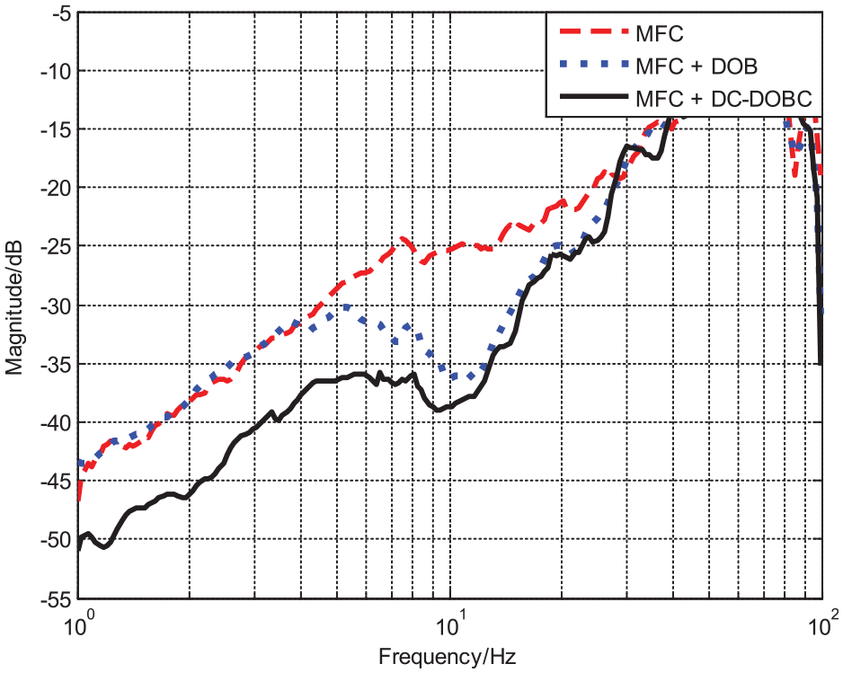
After experiments, the disturbance rejection capability in the frequency domain of the MFC system is shown as red line in Figure 9. In the low- and intermediate-frequency bands, the disturbance rejection capability mainly depended on the active disturbance rejection performance of the control system. In the high-frequency band, disturbance rejection capability mainly depended on the passive disturbance rejection performance of the mechanical structure of the ISP. However, the disturbances transmitted from movable platforms are mostly located at low- and intermediate-frequency bands.9–11 And the low-frequency disturbances have a non-negligible influence on the positioning accuracy of the LDLP system in the actual environments. Therefore, it is significant and necessary to reject the low-frequency disturbances with the ISP. Based on the built MFC system, the conventional DOBC method was introduced to reject more disturbances. The experimental disturbance rejection capability of the MFC system with the DOBC method is shown in the frequency domain as blue line in Figure 9. To compare with the DOBC method, the proposed DC-DOBC method was also introduced into the MFC system. With the dual compensators defined in equations (68) and (69), the disturbance rejection capability of the MFC system with the DC-DOBC method is shown in the frequency domain as black line in Figure 9.
Experimental disturbance rejection capabilities of the DOBC and DC-DOBC methods.
By comparing the lines in Figure 9, the conventional DOBC method could only improve the disturbance rejection capability in the intermediate-frequency band. It had no capability to reject more disturbances in the low-frequency band, because its single filter sacrificed the disturbance estimation capability to guarantee system stability. Different from it, the proposed DC-DOBC method with dual compensators had extra capability to estimate and reject the low-frequency disturbances with the additional compensator because the dual compensators with different stability restrictions could estimate disturbances in the different frequency bands simultaneously. As a result, the system with the DC-DOBC method could reject more disturbances over a wider frequency band than the system with the DOBC method. The experimental results in Figure 9 basically agreed with the simulated results shown in Figure 8. Compared with the smooth curves in Figure 8, the experimental curves in Figure 9 were unsmooth with fluctuations. The reason was that the vibrating frequencies of the vibrating platform were discrete when we tested the disturbance rejection capability in the frequency domain. The mechanical resonance of the ISP and measuring errors of the CCD brought the fluctuations, even though the experimental results were indeed in agreement with the simulated results. And the simulated and experimental results verified the effectiveness of the proposed DC-DOBC method.
Conclusion
In this paper, we focused on rejecting more disturbances of an inertially stabilized long-distance laser positioning system on a movable platform, which has a disadvantageous nonminimum-phase property. The conventional DOBC method sacrifices a lot of the disturbance rejection capabilities to guarantee the system stability when there is a nonminimum-phase property. To reject more disturbances of the inertially stabilized system, a DC-DOBC algorithm is proposed, which can be plugged into an existing inertial feedback loop. Although there is still a nonminimum-phase property of the inertially stabilized system, the dual compensators in the proposed method have different stability restrictions and different disturbance estimation performances. The analytical tuning laws for the dual compensators of the proposed method are presented. The proposed method introduces the additional compensator to offer extra capability to estimate and reject more disturbances in the low-frequency band. Therefore, the compensators have different disturbance estimation capabilities in different frequency regions. The disturbances are first estimated and rejected by one of the compensators once, after which the other one estimates and rejects the residual disturbances once again. Thus, the proposed method achieves the dual improvement on the disturbance rejection capability over a wider frequency range, rejecting more disturbances than the conventional methods. Comparative simulations and experiments were carried out to demonstrate the effectiveness of the proposed method.
Footnotes
Declaration of conflicting interests
The author(s) declared no potential conflicts of interest with respect to the research, authorship, and/or publication of this article.
Funding
The author(s) received no financial support for the research, authorship, and/or publication of this article.
ORCID iD
Yao Mao
References
1.
WangX-LCaiX-DSuZ-E, et al. Quantum teleportation of multiple degrees of freedom of a single photon. Nature2015; 518: 516.
2.
YinJCaoYLiY, et al. Satellite-based entanglement distribution over 1200 kilometers. Science2017; 356: 1140–1144.
3.
HilkertJMKangaGKinnearK. Line-of-sight kinematics and corrections for fast-steering mirrors used in precision pointing and tracking systems. In: Proceedings of SPIE, Airborne Intelligence, Surveillance, Reconnaissance (ISR) Systems and Applications XI 9076: 90760F.—the international society for optical engineering, Vol. 9076, Baltimore, MD, 9 June 2014.
4.
RabinovichWSMooreCIMahonR, et al. Free-space optical communications research and demonstrations at the U.S. Naval research laboratory. Appl Opt2015; 54: F189–F200.
5.
LeiYWangJZhangL. Full-scale measurement on vibration performance of vehicle-mounted optical transceiver mast. Meas Control2018; 51: 453–459.
6.
ZhangCJingXChenS, et al. Method of improving large-scale measurement accuracy of laser tracker based on photogrammetry. Meas Control2019; 52: 1220–1227.
7.
LuoYMaoYRenW, et al. Multiple fusion based on the CCD and MEMS accelerometer for the low-cost multi-loop optoelectronic system control. Sensors2018; 18: 2153.
8.
BigleyWJ. Supervisory control of electro-optic tracking and pointing. Proc SPIE1990; 173: 714–732.
9.
DongRAiYXiaoY, et al. Design and communication experiment of fine tracking system for free space optic. Infrared Laser Eng2012; 51: 731–741.
AntonelloROboeR. Exploring the potential of MEMS gyroscopes: successfully using sensors in typical industrial motion control applications. IEEE Ind Electron Mag2012; 6: 14–24.
KraftM. Micromachined inertial sensors: the state-of-the-art and a look into the future. Meas Control2000; 33: 164–168.
18.
KeckAPottJr-USawodnyO. Accelerometer-based online reconstruction of vibrations in extremely large telescopes. IFAC Proc Vol2014; 47: 7467–7473.
19.
TianJYangWPengZ, et al. Application of MEMS accelerometers and gyroscopes in fast steering mirror control systems. Sensors2016; 16(4): 440.
20.
MaoYDengJZhouX, et al. The frequency-domain fusion virtual multi-loop feedback control system with measured disturbance feedforward method in telescopes. Electronics2019; 8: 1103.
21.
GlückMPottJUSawodnyO. Piezo-actuated vibration disturbance mirror for investigating accelerometer-based tip-tilt reconstruction in large telescopes. IFAC2016; 49: 361–366.
22.
OhishiKNakaoMOhnishiK, et al. Microprocessor-controlled DC motor for load-insensitive position servo system. IEEE T Ind Elect1987; IE-34: 44–49.
23.
NakaoMOhnishiKMiyachiK. A Robust decentralized joint control based on interference estimation. In: Proceedings of the 1987 IEEE international conference on robotics and automation, Raleigh, NC, 31 March–3 April 1987.
24.
SunLLiDLeeKY. Enhanced decentralized PI control for fluidized bed combustor via advanced disturbance observer. Control Eng Pract2015; 42: 128–139.
25.
ZhouTLiuH. Distributed state observer design for networked dynamic systems. IET Control Theory Appl 2016; 10: 1001–1008.
26.
ZouQ. Adaptive sliding mode control for chain driving system with disturbance observer. Proc IMechE I J Systems Control Engineering. Epub ahead of print 24 January 2020. DOI: 10.1177/0959651819895693.
27.
ZhangGWangYWangJ, et al. Disturbance observer–based super-twisting sliding mode control for formation tracking of multi-agent mobile robots. Meas Control2020; 53(5–6): 908–921.
28.
ZhangJLiuXXiaY, et al. Disturbance observer-based integral sliding-mode control for systems with mismatched disturbances. IEEE Trans Ind Elect 2016; 63: 7040–7048.
29.
YangJChenWLiS, et al. Static disturbance-to-output decoupling for nonlinear systems with arbitrary disturbance relative degree. Int J Robust Nonlin Control2013; 23: 1850.
30.
LiuTGaoF. Enhanced IMC design of load disturbance rejection for integrating and unstable processes with slow dynamics. ISA Trans2011; 50: 239–248.
31.
ZhongQXieJ. Reduced-order time delay observer for LTI-SISO system with uncertainties. IET Control Theory A2002; 19: 885–891.
32.
NaJGriñóRCosta-CastellóR, et al. Repetitive controller for time-delay systems based on disturbance observer. IET Control Theory A 2010; 4: 2391–2390.
33.
XueWHuangY. Performance analysis of active disturbance rejection tracking control for a class of uncertain LTI systems. ISA Trans2015; 58: 133–154.
34.
HuQ. Variable structure maneuvering control with time-varying sliding surface and active vibration damping of flexible spacecraft with input saturation. Acta Astronau 2009; 64: 1085–1108.
35.
FangHYuanXLiuP. Active–disturbance–rejection–control and fractional–order–proportional–integral–derivative hybrid control for hydroturbine speed governor system. Meas Control2018; 51: 192–201
36.
GiapVHuangS. Effectiveness of fuzzy sliding mode control boundary layer based on uncertainty and disturbance compensator on suspension active magnetic bearing system. Meas Control2020; 53: 934–942.
37.
GaoFWuMSheJ, et al. Disturbance rejection in nonlinear systems based on equivalent-input-disturbance approach. Appl Math Comput2016; 282: 244–253.
38.
GuoLChenW. Disturbance attenuation and rejection for systems with nonlinearity via DOBC approach. Int J Robust Nonlin Control2005; 15: 109–125.
39.
TangTNiuSChenX, et al. Disturbance observer-based control of tip-tilt mirror for mitigating telescope vibrations. IEEE Trans Instrum Meas2019; 68: 2785–2791.
40.
DengCMaoYRenG. MEMS inertial sensors-based multi-loop control enhanced by disturbance observation and compensation for fast steering mirror system. Sensors2016; 16: 1920.
41.
ZhangHMaoYDengJ, et al. Three closed-loop feedback control system with dual disturbance observers of an optoelectronic stable control platform. Electronics2020; 9(2): 359.
42.
ChenWYangJGuoL, et al. Disturbance observer-based control and related methods: an overview. IEEE Trans Ind Elect2015; 63: 1083–1095.
43.
DengJRenWZhangH, et al. A modified disturbance observer structure based on acceleration measurement for disturbance suppression in tracking control system. Appl Sci2018; 8: 1571.
44.
CsencsicsESchitterG. System design and control of a resonant fast steering mirror for Lissajous-based scanning. IEEE/ASME Trans Mech2017; 22: 1963–1972.
45.
DongXZhangG. The signal-oriented test system model of automated test systems and its identification technology. Meas Control2019; 52: 869–878.