
Abstract
This article presents an extended state observer/proportion integration differentiation compound control scheme based on dynamic modelling for a three-axis inertially stabilized platform applied for aerial remote sensing. To reveal the effects of dynamic couplings among different gimbals and the base on the system control performance, the dynamic modelling of the inertially stabilized platform system is developed. Then, an extended state observer /proportion integration differentiation composite controller is designed to improve the tracking precision and stability of the inertially stabilized platform, whose disturbance rejection ability is analysed by simulations. During simulation analysis, the LuGre friction model is introduced to represent the effects of main disturbance torques. To verify the method, the experiments are conducted. The results show that the extended state observer/proportion integration differentiation compound scheme has excellent capability in disturbance rejection, by which the stabilization accuracy of the inertially stabilized platform has improved significantly.
Keywords
Introduction
Inertially stabilized platform (ISP) is a key component in an aerial remote sensing system, which is used to make the line of sight (LOS) of imaging sensors stable all along or tracking the objects in real time. 1 –5 In an aerial remote sensing system, the LOS of sensors must track accurately a fixed or moving target from an aircraft platform. Due to the effects of internal and external disturbances of the aircraft platform on the LOS, the imaging quality is seriously degenerated. So, the methods to attenuate the influences of disturbances are indispensable. The ISP is used to isolate the aircraft vibration so as to stabilize the imaging loads, by which the sensor’s LOS can track the target accurately in real time even the aircraft’s attitudes in any direction are changed. 1,2 In a study by Hilkert, 3 a three-axis ISP that can improve greatly the image quality through controlling the sensor’s LOS to achieve high pointing accuracy and stabilization is systematically introduced, including the case when the target is highly dynamic.
The most critical performance metric for an ISP is torque disturbance rejection. 4 Among various disturbances, friction, imbalance, vehicle motion kinematic coupling and sensor noise are predominant. Typically, the aerial ISP control system is configured as a high-bandwidth rate loop inside a lower bandwidth pointing or tracking position loop. The ISP might be viewed as a means for removing high-frequency disturbances and controlling the LOS. Therefore, a three-closed-loop compound proportion integration differentiation (PID) control scheme is an effective method for the ISP, which is composed of a current loop, a speed loop and a position loop. 5 However, the performances of the ISP only depending on the PID strategy cannot realize the high tracking accuracy due to the influences of multi-source disturbances. So, in order to effectively reject various disturbances, many methods are proposed. In a study by Lee et al., 6 to overcome the accuracy limitation of the simplified feed drive model, a distributed component friction model of a feed drive system is developed. In a study by Ruderman and Iwasaki, 7 a novel nonlinear friction observer aiming at the motion control is proposed. In a study by Lin, 8 an adaptive neural network control method is proposed to provide good accuracy in the identification of unknown model parameters. In a study by Chang and Zhou, 9 an acceleration-based feedforward compensator is proposed for the ISP to compensate the mass imbalance torque. Particularly, the dynamic coupling between different gimbals seriously affects the dynamic performance of a multi-axis ISP system. The growth of velocity and acceleration can enhance the coupling torque, even leading to system failures. Therefore, lots of decoupling methods are proposed. In a study by Zhou et al., 10 the inverse system method combining with the internal model control is proposed to deal with the nonlinearity and coupling of the ISP.
The active disturbance rejection control (ADRC) method has the unique characteristics of model independence and it actively rejects both internal and external disturbances. 11,12 The basic idea of this control strategy is the use of extended state observer (ESO), a novel observer for a class of uncertain systems, 13,14 to track the plant dynamics and unknown disturbances in real time and dynamically compensate for it in control effort. 12,15,16 With the accurate estimation of the plant dynamics and disturbances by the ESO, the ADRC can successfully drive the output of the drive axis to resonance. Recently, the ADRC is made only when control is taken as an experimental science, instead of a mathematical one. 17 The ADRC has been successfully employed in many electromechanical systems. 11,12,18,19
In this article, dynamic modelling is established first to reveal the coupling relationship among the ISP gimbals. Based on the simplified dynamic model, related simulation analyses are conducted and the result shows coupling torque is slight and can be neglected. Then, an ESO/PID controller is designed to promote the disturbance rejection ability of the ISP control system so as to improve the position precision. At last, to validate the proposed compound scheme, the simulations and experiments are performed.
Basic background
Aerial remote sensing system
Figure 1 shows the schematic diagram of an aerial remote sensing system. An aerial remote sensing system is generally composed of four main components, that is, a three-axis ISP, an imaging sensor, a position and orientation system (POS) and the aircraft vehicle. The role of the ISP is to act as a physical and intelligent interface between the imaging sensor and the aircraft. With the help of ISP, the influences of various disturbances either inside or outside the aircraft on imaging sensors are initiatively isolated, hence leading to high-resolution images. The POS, which is mainly composed of three main components, that is, inertial measurement unit (IMU), GPS receiving antenna and data processing system, is used to provide an accurate reference of position and attitude in the inertial space for the control system of ISP and imaging sensors through measuring imaging sensor’s angular movement. In the application, the IMU is generally installed on the top of the camera.
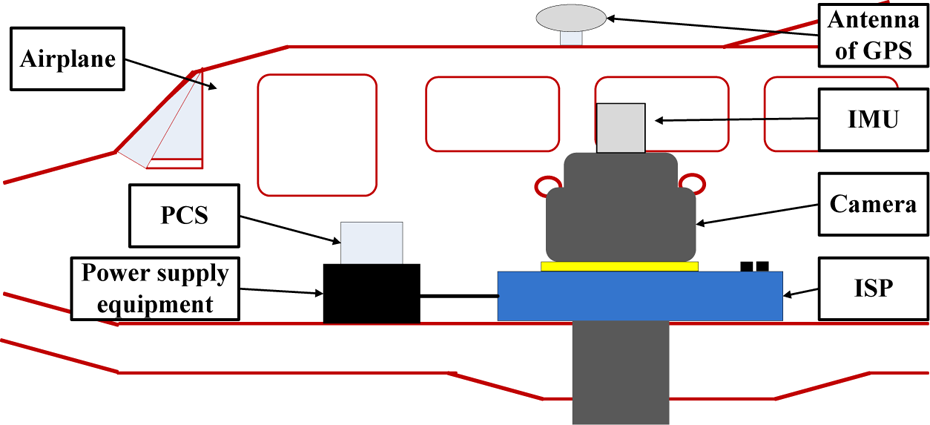
Schematic diagram of an aerial remote sensing system.
As shown in Figure 1, the three-axis ISP is mounted on the floor of aircraft, and the imaging sensor and the POS are mounted on the inner azimuth gimbal of the ISP. When the aircraft rotates or jitters, the control system of the three-axis ISP gets the high-precision attitude reference information measured by the POS and then routinely controls the LOS of imaging sensors to achieve accurate pointing and stabilizing relative to ground level and flight track.
Working principle of three-axis ISP system
Figure 2 shows the schematic diagram of the three-axis ISP’s principle. We can see that the ISP consists of three gimbals, which are azimuth gimbal (A-gimbal), pitch gimbal (P-gimbal) and roll gimbal (R-gimbal). Among them, the A-gimbal is assembled on the P-gimbal and can rotate around Za axis. Likewise, the P-gimbal is assembled on the R-gimbal and can rotate around Xp axis. The R-gimbal is assembled on the basement and can rotate around Yr axis. From Figure 2, we can see the relationships between three gimbals: rate gyros measure inertial angular rate of P-gimbal, R-gimbal and A-gimbal. Photoelectric encoders measure relative angular position between gimbals. Gimbal servo motors drive R-gimbal, P-gimbal and A-gimbal rotating inversely to keep the LOS of imaging sensors steady in inertial space.

3D-CAD picture of designed three-axis ISP and its driving motor and gear-driven system. ISP: inertially stabilized platform; CAD: computer-aided design.
Three closed-loop PID control system
Figure 3 shows the block diagram of traditional three-loop control system for the ISP. The three closed-loop PID control strategy, composed of a current loop, a speed loop and a position loop, is employed in the control of the ISP. The inner current loop is used to reduce the influence of voltage fluctuation from the power supply or the motor back electromotive force. The middle rate loop uses a rate gyro to measure the angular rate of the gimbal in the inertial space, which is used to compensate the difference between the rate command input and the angular rate of the gimbal, and then improve the steady-state precision. As to the main feedback path, the outer position loop takes the attitude angle measured by the POS as accurate references to ensure the accurate pointing of the LOS.

A block diagram of traditional three-loop PID control system for ISP.PID: proportion integration differentiation; ISP: inertially stabilized platform.
In Figure 3, the blocks of G-pos, G-spe and G-cur separately represent the controller in the position loop, speed loop and current loop; the pulse width modulation (PWM) block represents the power amplification used for the current amplify to drive the torque motor; the symbol L represents the inductance of a torque motor, R is the resistance, Kt is the torque coefficient of the motor and N is the transition ratio from the torque motor to the gimbals; Jm is the moment of inertia of the motor and Jl is the moment of the gimbals inertia along the rotation axis.
Dynamic modelling of three-axis ISP
Coordinate system
Figure 4 shows the coordinate systems of the three-axis ISP. For the convenience of the dynamic modelling and coupling analysis, a series of coordinate systems are established, 5 which are, respectively, named those of the base coordinate Oxbybzb (B-coordinate), the roll coordinate Oxryrzr (R-coordinate), the pitch coordinate Oxpypzp (P-coordinate) and the azimuth coordinate Oxayaza (A-coordinate). In each coordinate system, the origin O is the cross point of rotating axes of three gimbals, θr is the relative angle between the R-gimbal and the base, θf is the relative angle between the P-gimbal and R-gimbal, and θa is the relative angle between the A-gimbal and P-gimbal.

Coordinate systems of three-axis ISP. ISP: inertially stabilized platform.
Kinematic relationships of three-axis ISP
Three direction cosine matrices used in the angular rate coupling calculations are defined as follows:

In the roll coordinate, the roll gimbal rate

Likewise, in the pitch coordinate, the pitch gimbal rate

Likewise, in the yaw coordinate, the yaw gimbal rate

Dynamic modelling of three-axis ISP
Based on geometrical relationships, the Euler dynamic equation and vector superposition principle, the dynamic equations of the ISP are derived. Assuming that each gimbal is symmetrical relative to the corresponding coordinate system, the new Euler equations can be expressed as

where
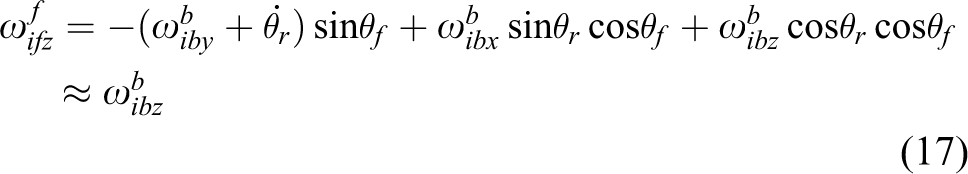
Dynamic equations of the yaw gimbal
Selecting the pitch coordinate(Oxfyfzf ) as the generalized coordinate, the projection of the yaw gimbal’s angular rate relative to the inertial space on the pitch gimbal coordinate system can be expressed as

where
When the yaw gimbal rotates around yaw axis, the projection of the angular momentum of yaw gimbal on pitch coordinate can be expressed as
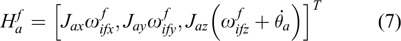
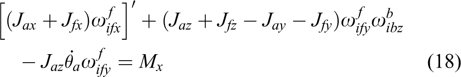
Assuming Jax = Jay and substituting equations (6) and (7) into equation (5), the dynamic equation of the azimuth gimbal can be described as

Dynamic equations of the pitch gimbal
The pitch gimbal structure system includes both of the azimuth gimbal and the pitch gimbal. When the pitch gimbal rotates around the pitch axis, the angular monument of the pitch gimbal system is composed of the angular monuments of the pitch and azimuth gimbals.
Selecting the pitch coordinate (Oxfyfzf ) as the generalized coordinate and assuming that the rotation axis of the pitch gimbal coordinate coincides with the inertia principal axis, the projection of the angular monument of the pitch gimbal system on the pitch gimbal coordinate system can be expressed as

So, three projection components of the angular monument of the pitch gimbal system along three coordinate axes can be expressed as

Substituting equations (3) and (10) into equation (5), the dynamic equation of the pitch gimbal can be described as

Dynamic equations of the roll gimbal
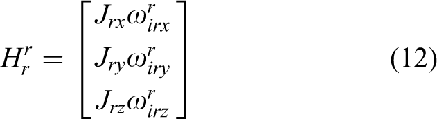
The roll gimbal structural system consists of the azimuth gimbal, the pitch gimbal and the roll gimbal. When the roll gimbal rotates around the roll axis, the angular monument of the roll gimbal system includes the angular monuments of the roll gimbal, the pitch gimbal and the azimuth gimbal.
Selecting the roll coordinate as the generalized coordinate and assuming that the rotation axis of roll gimbal coordinate coincides with the inertia principal axis of roll gimbal, the projection of the angular monument of the roll gimbal can be expressed as
Based on equation (9), through further transformation, the projection of the angular monument of the pitch gimbal system on the roll gimbal coordinate can be expressed as

So, the projection of the angular monument of the roll gimbal system on the roll gimbal coordinate can be expressed as
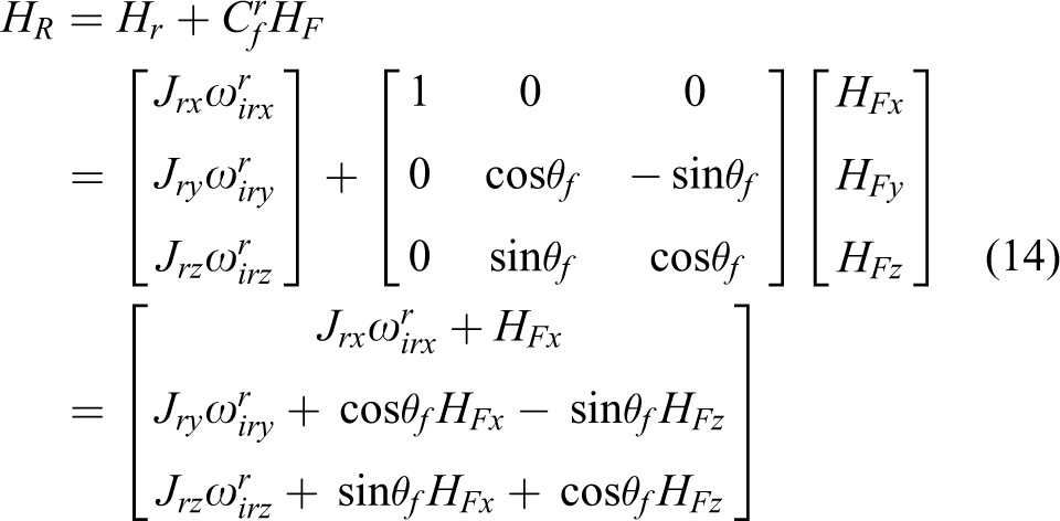
Substituting equations (2) and (14) into equation (5), the dynamic equation of the roll gimbal can be described as

Substituting equation (10) into equation (15), then get

Simplified dynamic equations
From equation (16), we can see there are couplings between the base and gimbals or inter-gimbals. However, since the rotation ranges of the levelling gimbals are very small for a heavy load three-axis ISP, generally, θr ≤ ± 5°, θf ≤ ± 5°, the dynamic equations can be approximately simplified due to small angle.
In the dynamic equation of the pitch gimbal,
Therefore, the dynamic equation of the pitch gimbal can be expressed as
In the dynamic equation of the roll gimbal, the parameters simplified are followed as


Therefore, the dynamic equation of the roll gimbal can be expressed as

Simulation analyses of coupling torque
Based on the actual applications of a three-axis ISP used for experiments, the parameters in simulations are set as
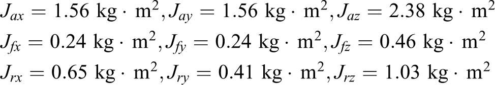
Figure 5(a) and (b) show the simulation results of the attitude angles of roll and pitch gimbals under moving base condition. As shown in Figure 5(a), the peak value error of roll attitude angle in steady state (t ≥ 100 s) is less than 0.054°, which is about 10% of total tracking errors. Likewise, from Figure 5(b), we can see that the peak value error of the pitch attitude angle is less than 0.002°, which only accounts for 0.4% of total tracking errors. Therefore, at the case of the small levelling rotation ranges, θr ≤ ± 5°, θf ≤ ± 5°, the tracking errors resulted by dynamic coupling torques only account for less than 10% or 0.4% of total tracking errors for the roll or pitch gimbals, respectively. So, during the investigation of the new methods for other disturbance rejection, to decrease the complexity of disturbances, dynamic coupling torques can be ignored approximately due to slight influences.
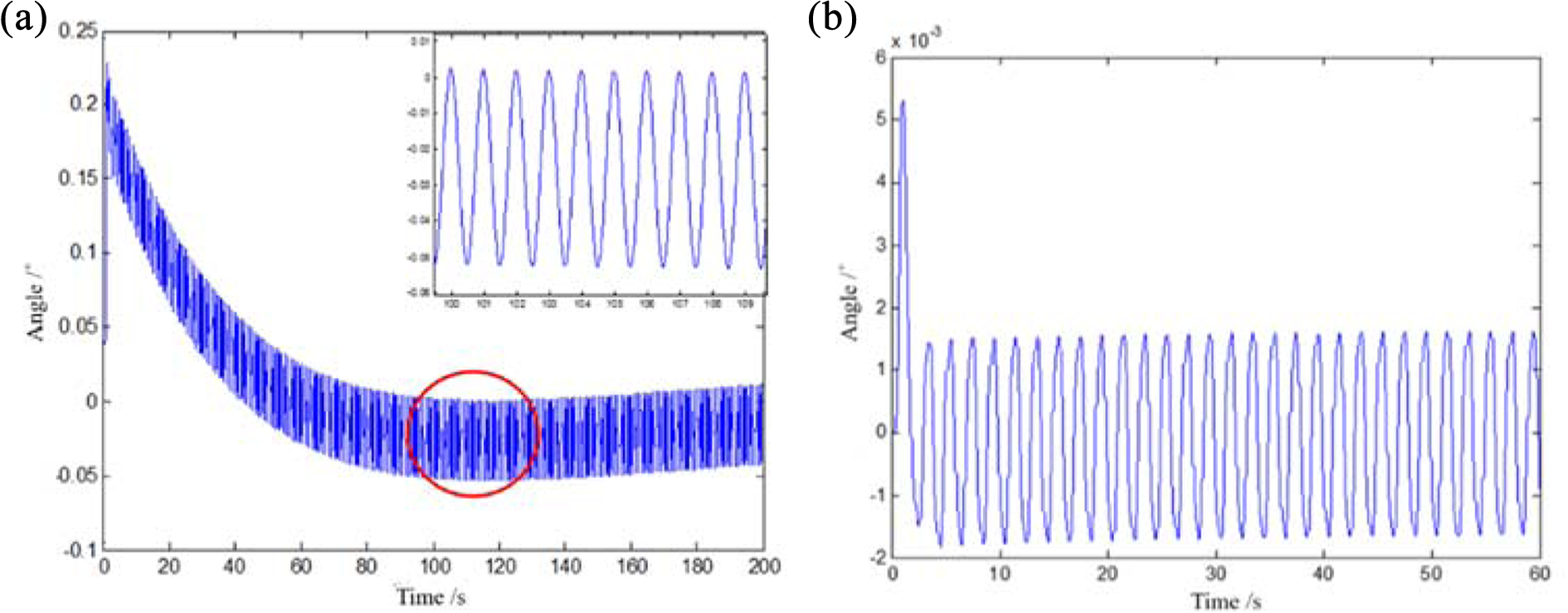
Simulation results of the attitude angles of roll and pitch gimbals under moving-base condition. (a) Roll attitude angle and (b) pitch attitude angle.
Control system design and simulation
Design of the control system model
In order to improve the precision of the control system, a composite control algorithm combining the ESO and the PID is proposed on the foundation of the modelling of the ISP system. In simulations, the LuGre friction model is introduced to represent the main disturbance. Figure 6 shows the scheme of three-loop compound control system.
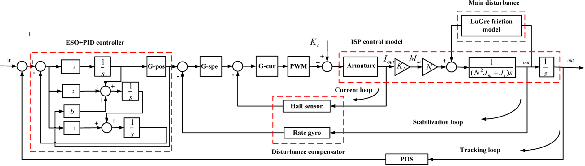
Scheme of three-loop compound control system.
Extended state observer
Based on the studies by Han
20
and Xue and Huang
21
for a linear system

Equation (24) can be rewritten as

where L is a matrix required for proper design.
For a nonlinear system

When b and f(x 1, x 2) are known, the state observer can be established
The error equation between functions (25) and (26) is

Assume the function is continuous and differentiable, Taylor expansion of the function (28) is

Under the condition that
However, if the function f(x 1, x 2) is unknown, the state observer which is constituted by the above method will not be able to observe the state variables of the system control object. For this two-order nonlinear system, f(x 1, x 2) can be extended to a new state variable x 3

In this way, the nonlinear system (26) can be expanded into a new linear system

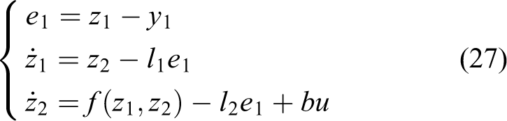
The ESO for this new linear system is established

We only need to select the appropriate parameters β 01, β 02, β 03, f(x 1, x 2) of the system that can be estimated by the estimation of z 1, z 2, z 3 in real time. In general, in order to avoid high-frequency tremor, |e|α sign(e) is transformed into a function with linear segment near the zero

where δ is length of the linear segment.

If f(x 1, x 2) contains the time variable t and unknown disturbance w(t), it can be estimated using z 3(t)

The real-time variable of the system can be obtained

Thus, function (32) is an ESO for system (26). ESO is actually a dynamic process that estimates the state variables of the control object directly using input information and output information of the control object, not using parameters and model of the control object directly.
ESO (32) is obtained in the observation of the nonlinear two-order system (26); for the two-order system as shown in function (26), the state variables and the real-time value can be observed with ESO.
So, for the multivariable, nonlinear and strong coupling of the three-axis ISP, ESO can observe the state variables and the real-time value, thus to further control.
Simulation analysis
In order to verify the effectiveness of the ESO/PID compound control algorithm, simulation and analysis are carried out. In aerial remote sensing, the pitch gimbal is more susceptible to disturbance torque than the other two gimbals, so the simulation and analysis are based on the pitch gimbal.
Given the input angle command θld = 0.5 sin(π ⋅ n ⋅ Ts ) deg, Td = 0, Figure 7 describes the disturbance rejection ability of conventional PID and ESO/PID compound controller.

Comparison of angle position responses to sine input between both of the normal PID and the ESO/PID compound. (a) Global curve and (b) partial enlarged curve. PID: proportion integration differentiation; ESO: extended state observer.
From Figure 7(a), we can see that the conventional PID and the ESO/PID compound controller has excellent tracking performance for sinusoidal signals. However, in Figure 7(b) of the partial enlarged curve, it can be seen that the conventional PID has the error of 0.01° in tracking the sinusoidal signals and the ESO/PID compound controller coincides with sinusoidal signals nearly. Therefore, the ESO/PID compound control method makes the system has more strong disturbance rejection ability, even if it is subjected to friction, the system can still track the given signals in real time, and the tracking error is almost zero.
Figure 8(a) and (b) describe angular error for the PID and the ESO/PID in without friction and with friction conditions. It can be more clear to describe the conventional PID controller and the ESO/PID compound controller for tracking sinusoidal signal performance. Figure 8(a) shows that in the absence of interference, the conventional PID has the angular error between −0.02° and 0.03°, and the angular position error of the ESO/PID compound controller has been stable in the vicinity of 0°.
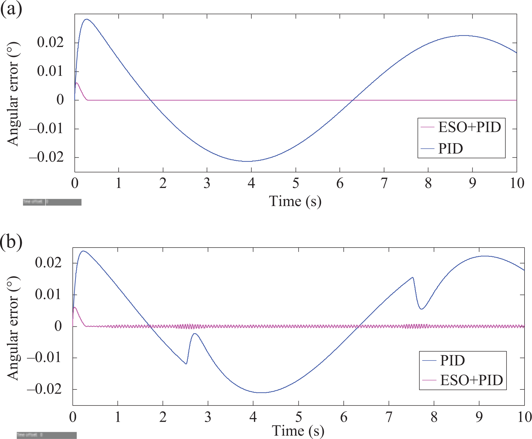
Compared curve of angular error for PID and ESO/PID. (a) Compared curve without friction and (b) compared curve with friction. PID: proportion integration differentiation; ESO: extended state observer.
As shown in Figure 8(b), after adding friction, conventional PID and the ESO/PID compound controller have almost the same change range of angular error with not adding friction, but there are some fluctuations. Although the angular error of the ESO/PID composite controller is fluctuating, it is still stable in the vicinity of 0°. It shows that the tracking performance of the ESO/PID composite controller is more accurate and more stable than that of the conventional PID in the interference condition.
Experimental verification
To verify the validity and practicability of the ESO/PID compound controller, experiments are carried out by three-axis ISP. As shown in Figure 9, the experimental system contains the ISP, upper computer, simulated load and power supply equipment providing power to the ISP. The ISP’s weight is 40 kg, and the weight of simulated load is 20 kg, the largest weight that the ISP can carry is 80 kg. The maximum levelling rotation angle range is ±5° and the maximum heading rotation angle range is ±25°. The height of the ISP is 150 mm.

Picture of experimental system. (a) Upper computer, (b) power supply, (c) simulated load, and (d) ISP. ISP: inertially stabilized platform.
In order to evaluate the adaptability of the ESO/PID compound controller in the ISP, experiments both on the roll gimbal and on the pitch gimbal are carried out. In the experiments, the ISP is in the levelling work mode, in which the deviation angles away the local gravity line measured by two accelerometers are as the attitudes references. The angular position errors of roll and pitch gimbals, θr and θp , are taken as the metric to evaluate the method. As a comparison, the results obtained by the PID are also displayed.
The horizontal angle of the roll gimbal has been set at 0 degree, the sampling cycle at 6000 and the sampling frequency at 50 Hz. It is shown in Figure 10 that conventional PID has large fluctuations compared to the ESO/PID under the same circumstances. After specific calculation, the root mean square (RMS) of the conventional PID control method is 0.0990 degree and the RMS of the ESO/PID compound control method is 0.0661 degree, decreases by 33.23%. It can be seen that the ESO/PID control method has better control precision and disturbance rejection ability than the conventional PID control method.

Graph of level by PID and ESO/PID of the roll gimbal. PID: proportion integration differentiation; ESO: extended state observer.
The horizontal angle of the pitch gimbal has been set at 0 degree, the sampling cycle at 6000 and the sampling frequency at 50 Hz. It is shown in Figure 11 that conventional PID has large fluctuations compared to the ESO/PID under the same circumstances. After specific calculation, the RMS of the conventional PID control method is 0.1009 degree and the RMS of the ESO/PID compound control method is 0.0454 degree, decreases by 55.01%. It can be seen that the ESO/PID control method has better control precision and disturbance rejection ability than the conventional PID control method. Table 1 is the comparison of the RMS of two control methods.

Graph of level by PID and ESO/PID of the pitch gimbal. PID: proportion integration differentiation; ESO: extended state observer.
RMS errors of different control methods.

PID: proportion integration differentiation; ESO: extended state observer; RMS: root mean square.
Conclusions
In this article, an ESO/PID compound control scheme is proposed to promote the disturbance rejection ability of a three-axis ISP for aerial remote sensing applications. Particularly, the dynamic modelling is developed to reveal the effects of dynamic couplings among different gimbals and the base on the system control performance. To verify the method, the simulations and experiments are conducted. The results show that the ESO/PID composite scheme has excellent capability in disturbance rejection, by which the stabilization accuracy of the ISP has improved significantly. Compared with the conventional PID controller, the RMS errors of roll and pitch system under static base condition are decreased up to 33.23% and 55.01%, respectively.
Footnotes
Declaration of conflicting interests
The author(s) declared no potential conflicts of interest with respect to the research, authorship, and/or publication of this article.
Funding
The author(s) disclosed receipt of the following financial support for the research, authorship, and/or publication of this article: This work was supported by the National Natural Science Foundation of China (No. 51775017, No. 51375036 and No. 51205019) and the China Scholarship Council (No. 201306025015).