
Abstract
This article presents the conceptual design of a novel compliant microelectromechanical systems (MEMS)-based gripper with integrated electrothermal actuator and electrothermal force sensor. By this design solution, the device possesses some unique characteristics including a small and compact footprint size, and a large driving force by the thermal actuator. Owing to the use of a compliant rotational bearing, a large gripping range is obtained. The sensing arm has a capability of detecting the force transmitted from the left arm so as to prevent the damage of the grasped object. Analytical models are developed to evaluate the statics and dynamics performance of the gripper. Simulation results show that the thermal actuator produces sufficient gripping force to execute the gripping operation with a range of 80 µm under a low input voltage of 6 V. Moreover, the results of the established theoretical models match well with the finite element analysis (FEA) simulation results, which verifies the feasibility of the proposed gripper design.
Introduction
MEMS-based microgrippers have been employed in some application areas, such as micromanipulation, microassembly 1 and material characterization. 2 It plays an important role in executing the process of grasping and releasing biological samples like cells and bacteria. 3 In the previous work, various types of microgripper were introduced, which propose different mechanical structures, actuation methods and sensing principles. This article presents the design and simulation of a novel microgripper, which exhibits a compact structure with an integrated thermal type of actuation and force-sensing capabilities.
Structure design, actuator design, and sensor design are the major design issues for a MEMS microgripper. A compliant mechanism (a mechanism which is compliant) is employed to design the gripper structure in this work, as it has inherent merits: no friction, no clearance, no wear, lubrication free and ease ofmanufacture. 4 In the meantime, the compliant mechanism transfers the displacement following the property of the used material elastic deformations. 5 Therefore, the compliant mechanism can realize the smooth and repeatable motion of the microgripper. For this reason, the compliant structure has been popularly applied in MEMS devices, especially for the applications which need ultra-high precision motion. 6 Hence, the gripper structure is designed using a compliant mechanism in this work.
The actuator is a necessary tool to generate the desired displacement with a proper input force. MEMS grippers have some requirements, like a sufficient large driving force and displacement. Generally, the actuation approaches are mainly categorized into four classes in terms of electrostatic actuator, 7,8 electromagnetic actuator, 9 piezoelectric actuator, 10 and electrothermal actuator. 11 As for the electrostatic actuator, two main problems are the small range of the displacement and a relatively high driving voltage. Electromagnetic actuators have shortcomings such as: a complex fabricating process, high-power dissipation, large gripper dimensions because of the needed external magnetic field. A piezoelectric actuator calls for a sophisticated control technique to realize a precise grasping process due to the hysteretic nonlinearity of displacement output. Speaking of the electrothermal actuator, it provides some unique capabilities, such as supplying a large force and displacement with a relatively low voltage. 12,13 Also, much attention has been paid to thermal actuators in recent years, which have been demonstrated to be more compact and stable. 11 Actually, electrostatic and electrothermal actuators are two main means of creating in-plane motion in MEMS devices. Compared to an electrostatic actuator, a thermal actuator can easily achieve the output force of 1 mN at the excitation voltage of 5–10 V, 14 while it is impossible for the electrostatic actuator to generate such a force scale under a low voltage. Hence, the thermal actuator is selected for the gripper actuation in this work.
Another design issue of the microgripper is sensor design. During the process of grasp-handle-release of the object, the force experienced by the gripper should be measured to ensure the microobject’s safety. 15 Force sensing is of great importance to detect the gripping force exerted on the samples. Various types of sensors have been reported in the literature. Chen et al. 16 demonstrated that a piezoresistive force sensor can provide real-time information of the gripping force. However, its performance is limited by the complicated assembly process. Capacitive sensors are low cost and easy to fabricate; however, their large dimension is a big obstacle to compact design. In this article, a thermal sensor is employed because it exhibits merits such as high-precision force detection, as well as compact size.
The motivation of this article is to design a compact microgripper which is equipped with an electrothermal actuator and electrothermal force sensor. As compared with existing designs of microgrippers, 17 –19 the proposed gripper structure achieves a larger force and displacement with a relatively low voltage. Also, it offers a precision force measurement in a very small footprint. The following parts of this article are organized as follows. In the following section, the details of the mechanism design of the microgripper are presented. FEA simulation studies are conducted in the section “FEA Simulation Results” to testify to the effectiveness of the parameter design and analytical modeling. The next section discusses some capabilities of this gripper, followed by our concluding section.
Design of the gripper
A sketch diagram of the microgripper is presented in Figure 1. This gripper consists of a series of Z-shaped thermal actuators in the left arm and the thermal force sensor in the right. There are four actuation flexures to support the thermal actuator, which is connected to the rotational bearing of the left arm. The output force produced by the actuator is translated by the rotational mechanism, and then the input displacement is amplified at the left tip. The thermal sensing arm is also supported by four flexures. It is notable that the two ends of the Z-shaped central beam are connected by the dielectric glue to ensure that the electric current only flows in the actuator. With the rotational bearing, the input displacement is easily transferred from the direction of the y-axis to that of the x-axis. Due to the compliant mechanism design, there exists some lost motion during the gripping motion. As compared to the gripping range, the lost displacement on the left tip is so small that it can be neglected.

Parameters of of the MEMS microgipper.
Thermal actuator design
To execute the in-plane motion drive, the thermal actuator works based on the principle of thermal expansion. There are several popular configurations of the thermal actuators: namely, a pseudobimorph thermal actuator, 20 the bent beam (V-shaped) thermal actuator, 21 the Z-shaped thermal actuator. 11 Each configuration of the actuator has specific characteristics. Concerning the pseudobimorph type, it has asymmetrical beams with different cross-section areas, whose motion path is an arc produced by the thermal expansion of beams. The V-shaped actuator uses the symmetric configuration of two slanted beams. By this scheme, the central shuttle of the actuator can achieve rectilinear motion in one direction. Hence, the V-shaped thermal actuator has been widely used in many applications, such as nanopositioners, 22 micro engines, 23 and nanoscale material testing systems. 24
However, there are two main restrictions of the V-shaped thermal actuator. The first comes from the slanted beams, which lead to manufacturing problems in small features, especially when fabricating the smooth sidepieces. It decreases the resolution of photolithography for the beam width. Relatively large stiffness (approximately 1000 n/m) is another limitation of V-shaped beams. Due to the aforementioned problems, the V-shaped thermal actuator is not suitable for acting as a load actuator and sensor simultaneously. To overcome these problems, a Z-shaped thermal actuator is employed in the microgripper design. It has the merits of a large range of stiffness as well as output force.
The diagram of a Z-shaped beam is illustrated in Figure 2. It is a symmetric structure, which is composed of two Z-shaped beams and a shuttle in the center of the beams. The operating principle of this actuator is similar to the V-shaped actuator. Due to thermal expansion, the central shuttle is guided by the bending beams to generate a rectilinear displacement. When the thermal expansion is caused by a current flowing through the whole structure, because of the Joule heating effect, the temperature of the beams increases, culminating in thermal expansion. In Figure 2, h represents the beam width and S is the length of the long arm. At a given temperature, the increasing length influences the output displacement proportionally. With other parameters unchanged, the length of the central beam s increases and the output displacement decreases. The stiffness is only influenced by the thickness and the number of multiple Z-shaped beams.

The diagram of a single Z-shaped thermal actuation beam.
Analytical modeling
We consider the theoretical model by considering the coupling of electrothermal and thermomechanical effects. To analyze the latter, we adopt the following hypotheses: that the central shuttle is inflexible and there is barely any thermal deformation; that the short beam deformation of the thermal expansion is neglected. 25 When using the energy method, three reaction forces/moments—the axial force F, the virtual force G, and the moment M—are considered when solving 26
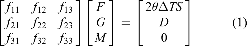
where θ is the coefficient of thermal expansion of silicon, ΔT is the average temperature increase in the beams, S is the length of the long beam (see Figure 2), and D represents the output displacement from the thermal actuator. In addition, the elements of the aforementioned matrix are shown as follows
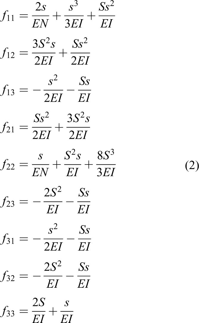
where E is Young’s modulus of the actuator material—silicon, and s is the central beam length of the Z-beam (see Figure 2). Additionally, N represents the cross-section area of the Z-beam and I is the moment of inertia.
The stiffness Kz of an entire Z-shaped beam can be expressed by

where h1 and t1 represent the width and thickness of the Z-shaped beam, respectively.
The average temperature increase ΔT on the Z-shaped beam has a relationship with the excitation voltage V1 27
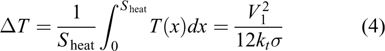
where Sheat is the entire length of Z-shaped beam, kt and σ are the thermal conductivity and the resistivity of the material (silicon), respectively.
Mechanism design of actuator
The stiffness of the rotation arm bearing can be calculated by referring to the literature 28

where E, t2, and h2 are Young’s modulus of silicon, thickness of the gripper, and width of the torsional flexures, respectively. In addition, r and B are inner radius and length from the end of the rotary bearing to rotation axis point P, respectively. The length of the arm beam flexures is represented by d.
The spring constant of the four actuation flexures can be expressed by

where la is the length of the flexures, and h3 is the width of actuation leaf flexure.
Because of the parallel connection of the two spring constants Kr and Kf, and also considering the stiffness of the Z-shaped beams Kz, so the overall stiffness of the left arm can be expressed as 29
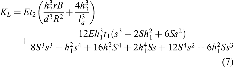
where B = r + d.
By combining (3), (4), and (7), the output force of the Z-shaped thermal actuator can be calculated as follows

In the view of (1), (2), (4), and (7) the driving displacement can be computed by

The displacement amplification ratio of the left tip can be calculated by

where R and L are the driving distance and arm length of the gripper, respectively.
Then, the gripping displacement range of the left tip can be derived as

It is notable that the gripping force has a relationship with the driving force as follows

Taking into account (10) and (12), the total stiffness in the left tip can be derived below
Design of the sensing arm
In this research an electrothermal sensor is employed to detect the force in the right tip exerted by the object gripping operation. This thermal resistive sensor has been recently used in the literature. 17 The sensing principle is illustrated in Figure 3. This kind of electrothermal sensor not only has merits such as high resolution, but also offers a large detection range, which can protect the manipulated object very well.

Working principle of the thermal sensor.
It is observed that the sensor consists of two resistive beams arranged in parallel, which are made of doped silicon. There is a heat sink plate, which is connected to the sensing arm fixed by four flexures. It is placed near two beams with an air distance of 2 µm. On applying the voltage to the beams, the current through the beams leads to the temperature change in the heat sink plate. When the plate stands steady in the middle of two thermal resistors, the heat fluxes in the sensors do not vary. In other words, temperature and resistance are equal for each sensor. Once the sensing arm induces a displacement, the heat sink plate is moved forward in the displacement direction (+y-axis). And then, the flux increases in the right sensor (Rr). By contrast, the flux of the left sensor (Rl) is decreased. The resistance change follows the same regulation of the flux changing. Hence, the displacement measurement of the sensing arm can be conducted by detecting the different values between the two resistors. When a force is generated on the right arm, it leads to a displacement in the moving plate. The current diversification in two resistors caused by the displacement difference is converted into the output voltage signal, which is conducted via a half-Wheatstone bridge integrating with an instrumentational amplifier.
Principle of sensor
Four leaf flexures are used to fix the sensing tip. The overall stiffness can be computed by

where h4 and ls represent the width and the length of leaf flexures connecting to the sensing arm.
Based on (12) and (14), the displacement of the right tip can be expressed as follows

Assume that the temperature distribution T from each resistor beam is uniform. The resistance and temperature values Rm(


where Rc represents the resistance of a resistor with a constant temperature Tc. The resistance of the resistor changes along with the temperature degree diversification due to the γ effect, which is called the coefficient of constant temperature. In addition, thermal conductance is Q


where
Dynamic modeling
To determine the natural frequency of the microgripper, dynamic analysis is induced in this part. First, based on the pseudo-rigid-body (PRB) method, the stiffness of a leaf flexure can be computed by
4

where λ = 0.85 is the optimal value of the characteristic radius, Kα = 2.67 is the stiffness coefficient, l is the length of leaf flexure and τ represents the area moment of inertia, which can be expressed as

where t and h are thickness and width of the flexure, respectively.
The kinetic energy function for the actuation system can be derived as follows

where q is the displacement of the central beam of actuator in working direction, ma represents the mass of central beam, mb is the mass of the leaf flexure, mc is the quality of the rotating bearing, md, me and mz express the masses of left arm, the leaf flexure connecting to rotational bearing and the Z-shaped actuator, respectively.
The potential energy of the actuation system can be calculated as follows

where δ1 and δ2 are the deformations, and K1 and K2 are the stiffnesses of the flexures which are linked to the actuator and rotational bearing, respectively. In addition, K3 is the overall stiffness of Z-shaped beams.
By considering Lagrange’s equation, the relationship between kinetic energy and potential energy can be established as follows

In order to calculate the natural frequency of the microgripper, the external force Fex is set to be zero. The dynamic model is derived as follows

where the equivalent mass My and stiffness Ky of the left actuating system are expressed as


Hence, the natural frequency (in units of Hertz) in one working direction of the gripper can be derived as

Following the same principle, the natural frequency in the sensing direction can be calculated by considering the kinetic and potential energies. The kinetic function during sensing motion can be expressed as
where mf, mg and mh represent the masses of the right arm and leaf flexure, which are linked to the sensing arm and the move-plate respectively.
The potential energy Vx in the sensing process is computed as follows

where K4 is the stiffness of leaf flexure which is connected to the sensing arm.
Substituting Tx and Vx into Lagrange’s function (25), the natural frequency (in Hertz) in the sensing direction can be calculated below

where the equivalent mass and stiffness are shown below


FEA simulation results
Simulation results of the actuator
To simulate the performance of the Z-beams thermal actuator, ANSYS 16.2 software is employed to conduct multiphysics simulation in this work. This electro-thermal actuator needs an analysis environment of a coupled field, including electric, thermal and mechanical fields. The parameters of the employed silicon material are listed in Table 1.
Material properties of the gripper. 31

For a simulation study, the boundary conditions need to be considered. Regarding the thermal conditions, zero temperature change is applied to anchors. In addition, mechanical boundary conditions are applied by fixing the support of the anchors. An electric boundary condition is considered by applying the voltage to the anchors. As the result of our multiphysics simulation, the displacement and the temperature distributions of the actuator are obtained. As the input voltage increases, the corresponding maximum displacement increases as well. In this work, to generate an operational gripping range of 80 µm, only 6 V is enough for the drive. The simulation results are illustrated in Figures 4 and 5. Moreover, the relationships of the input voltages, output displacements, and the number of Z-beams are obtained as shown in Figure 6. The overlapping curves indicate that increasing the number of Z-shaped beams does not influence the output displacement, and it only contributes to the increase of the stiffness for the whole structure.

Simulation of output displacement of the thermal actuator by applying a voltage of 6 V.

Simulation of temperature distribution on the thermal actuator by applying a voltage of 6 V.

The influence of the number of Z-beams on the output displacement by applying different voltages.
Simulation results of the structure
To ensure the authenticity of the FEA simulation process, it is indispensable to take into account the thermal actuator. In this article, ANSYS software is used for both static and modal simulation studies. The main parameters of the gripper are listed in Table 2.
Main parameters of the microgripper.

Static analysis
In order to simulate the real working condition of the gripper, the stiffness of Z-shaped beams is also considered. Thus, by referring to the simulation result of a sole actuator, the input force Fin, that guarantees the operation gripping range of 80 µm, can be computed as 6575 µN. This force is applied at the actuation end of the gripper. The results of static simulation are shown in Figure 7(a). From the simulation results of the deformations in x and y-axis directions, the stiffness KL of left arm and the displacement amplification ratio C of the lever amplifier are calculated. Similarly, by executing a gripping force Fg = 1 µN on the right tip, which is calculated via (12), the stiffness of the right tip can be computed from the simulation results, as shown in Figure 7(b).
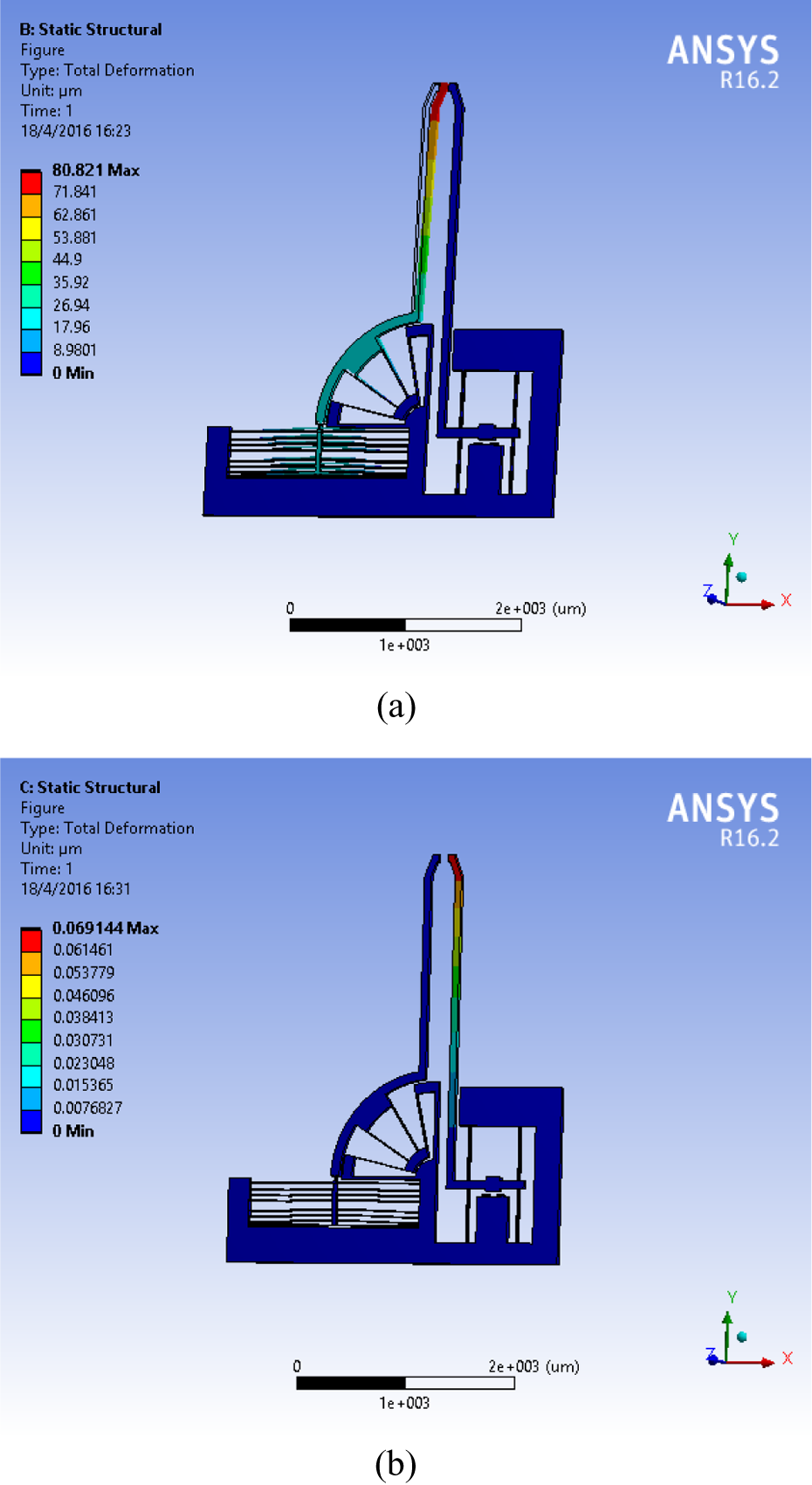
Simulation results of static analysis: (a) the actuation arm is driven by an input force of 6575 µm; (b) the sensing arm is exerted by a 1 µN gripping force.
Modal analysis
To check and verify the dynamic performance of the structure, a modal analysis is carried out. The results of the modal analysis simulation are shown in Figure 8. The two concerned resonance frequencies of the gripper are 4487.70 Hz and 4654.30 Hz, which occur at the actuating and sensing arms, respectively. The simulation results show that the gripper has a good dynamic performance in terms of resonant frequency, which predicts that the gripper has some fine features: such as, applicability and stability.

Simulation results of the first resonance mode for: (a) The actuation arm and (b) the sensing arm.
Discussion
The comparison of the analytical and FEA simulation results is shown in Table 3. Taking the simulation results as a benchmark, it is seen that the maximum errors between the analytical model and simulation results for the stiffnesses of the actuating and sensing arms are below 10%. In view of the natural frequencies of the gripper system, the errors are lower than 6%. In addition, regarding the displacement amplification ratio of the actuation arm, the analytical model result is very close to the simulation result with a deviation of less than 2%. The discrepancies between the modeling results and simulation results may come from the established analysis models, which only consider bending deformations, while the simulation study takes into account every kind of deformation. More accurate analysis models will be derived in future work. Moreover, it is observed that the stiffness of the sensing arm is relatively higher than the stiffness of the actuating arm, which indicates that the sensing arm is stiffer and experiences a smaller deformation during the grasp operation.
Comparison of analytical model with simulation results.

It is notable that Z-shaped beams are connected to the gripper structure by using insulation adhesive against the current flow through other parts of the gripper. In this work, it is assumed that the glue does not influence the stiffness of the whole actuating part.
In practice, a high natural frequency of this gripper is desirable. The simulation study verifies the accuracy of the established analytical models. In addition, the relatively high natural resonant frequencies of 4487.70 Hz and 4654.30 Hz are attributed to the actuation and sensing arms, respectively. It is known that a high frequency enables a large bandwidth of control. Hence, in future work, when the control system is added, this high frequency should contribute to the generation of acceptable performance for the control system. The analytical and simulation results reveal that the gripper exhibits a good dynamic performance when it is fabricated and used in real work. Moreover, the analytical result is consistent with the simulation result, which provides a good basis for further work on the optimal design of a gripper structure.
Compared to the existing microgrippers, the superiority of this design is obvious. For instance, the grippers as proposed in the literature 17 –19 deliver gripping strokes of 15 µm, 60 µm, and 85 µm from high input voltages of 60 V, 100 V, and 80 V, respectively. In this article, a large gripping stroke of 80 µm can be easily achieved by a relatively low excitation voltage of 6 V, which is contributed by the prominent capability of the employed Z-shaped thermal actuator along with a new structure design. There are also some MEMS grippers actuated by thermal actuators in previous work. For instance, a microgripper with integrated V-beam thermal actuator is reported in the literature. 32 This actuator generates a force in the y-axis direction, and the force is transmitted from the y-axis to the x-axis direction by using a displacement amplification flexure. While this flexure causes a relatively large displacement loss in the vertical direction, it is not so accurate when executing a grasping operation. In the proposed work, a rotary guiding flexure mechanism provides good performance in reducing the unwanted loss in displacement. In addition, an electrothermally actuated gripper can be found in the literature. 33 This gripper has a simple working principle. However, the complex mechanical structure complicates the manufacture process. By comparison, the Z-shaped thermal beam presented in this article has the merits of easy fabrication, and less influence of manufacture error on the functionality of the gripper.
As for the initial open condition, the clearance between the two tips of the gripper is set at 100 µm. It is notable that the gripping range of 80 µm is obtained by a relatively low voltage (6 V). If a larger gripping displacement is needed, a higher voltage can be applied. In addition, the clearance between the two tips can be redesigned to be any size to satisfy the grasping requirements of different sized microobjects. Meanwhile, the compact design of the microgripper with the integrated thermal actuator and sensor exhibits a small footprint of 3.22 mm × 3.77 mm, which contributes to the cost reduction of the microfabrication. It is notable that the footprint can be further reduced by adopting the optimal design of the gripper architecture.
Conclusion
A novel compact microgripper has been designed in this work, consisting of: A compliant mechanism structure, an electrothermal actuator, and an electrothermal sensor. Benefiting from the new design concept, the footprint of the entire gripper is only 3.22 mm × 3.77 mm. At the same time, with a less than 10 V driving voltage applied to the Z-shaped thermal actuator, a large output force from the actuator is obtained. It is easy to execute the gripping displacement range of 80 µm at a low voltage of 6 V. In order to prevent the grasped object from damage, a thermal force sensor is designed for the sensing arm which has the merits of high resolution and large measurement range. Our simulation results verify the feasibility of this proposed MEMS gripper design. In future work, the gripper will be fabricated and the control system will be developed to further verify the function of the microgripper through experimental studies.
Footnotes
Declaration of conflicting interests
The author(s) declared no potential conflicts of interest with respect to the research, authorship, and/or publication of this article.
Funding
The author(s) disclosed receipt of the following financial support for the research, authorship and/or publication of this article: This work was supported in part by the Macao Science and Technology Development Fund under Grant No. 090/2015/A3 and 052/2014/A1, and in part by the Research Committee of the University of Macau under Grant No. MYRG078(Y1-L2)-FST13-XQS.