
Abstract
This paper presents the structural design and analysis of a novel compliant gripper based on the Scott-Russell (SR) mechanism. The SR mechanism in combination with a parallelogram mechanism enables the achievement of a pure translation of the gripper tips, which is attractive for practical micromanipulation and microassembly applications. Unlike traditional pure-translation grippers, the reported SR-based gripper exhibits a simple structure as well as compact dimension because the in-plane space is fully used. The kinematics, statics and dynamics models of the gripper mechanism are established, and finite element analysis (FEA) simulations are carried out to verify the structure design. A prototype has been developed for experimental testing. The results not only demonstrate the feasibility of the proposed SR-based gripper design but also reveal a promising performance of the gripper when driven by piezoelectric stack actuators. Moreover, several variations of the gripper structure are presented as well.
Introduction
Robotic micro- and nano-handling systems are important to realize the automated manipulation and assembly of objects in micro- and nanometre scales [1]. As a crucial device in micro-handling systems, the microgripper has attracted intensive attention from both academia and industry. According to the driving principle, various types of microgrippers have been previously proposed, including electrostatic [2], electrothermal [3] and piezoelectric microgrippers [4]. The piezoelectric actuator in particular is attractive thanks to its properties of quick response speed and ultrahigh positioning resolution [5, 6]. Therefore, a piezoelectric stack actuator (PSA) is employed for the drive in this research.
Concerning the structure design, a great number of microgrippers have been devised using compliant mechanisms. The reason lies in the fact that, as compared with traditional bearings, compliant mechanisms produce motion by making use of elastic deformation of the material. Hence, compliant mechanisms offer some advantages in terms of being backlash-free, friction-free and lubrication-free [7–11]. However, most of the existing microgrippers are constructed with two arms, which work based on rotary motion [12]. It is known that the reaction force will appear at the contact point once the gripper tips make contact with the target object. When grasping some objects which have a curved surface, the reaction force may push the grasped object away from the gripper tips [13]. Hence, it is desirable to devise microgrippers whose tips provide a pure translational motion [14,15]. Nonetheless, the majority of parallel-motion grippers possess a complex structure [13,14], which complicates the analysis and fabrication procedures.
The motivation of the present research is to devise a new parallel-motion gripper with a simple structure. Specifically, a Scott-Russell (SR) mechanism and a parallelogram mechanism are adopted to design the structure of each gripper arm. The SR mechanism has been previously employed to develop micropositioning systems. For instance, two SR mechanisms were used in [16] to construct a two-level amplification of PSA stroke for the actuation of a micropositioner. An optimal design of the SR-based micropositioning mechanism was presented in [17] with the aim of achieving a maximum amplification of the small displacement of PSA. More recently, an SR mechanism was employed in [18] to devise an ultraprecision rotary micro-positioning stage. However, limited effort has been made in the literature towards the extension of theSR mechanism to gripper design. In this work, a novel compliant gripper is devised based on an SR mechanism. It is shown that the employment of an SR mechanism facilitates the structural design of a gripper with a simple architecture. In comparison with traditional microgrippers, the proposed SR-based gripper allows the generation of a simple structure. Moreover, a compact dimension is achieved since the in-plane area has been fully used. The feasibility and performance of the proposed gripper is validated through both finite element analysis (FEA) simulations and experimental studies.
In the remainder of this paper, the mechanism design process of an SR-based compliant gripper is presented in Section 2. Section 3 and 4 presentkinematics modelling and stiffness, static and dynamic analyses, respectively. Section 5 describes the finiteelement analysis simulation which is conducted by ANSYS. Afterwards, a prototype microgripper is fabricated in Section 6 along with an account of open-loop performance. Discussions about the gripper performance and future work are reported in Section 7. Finally, Section8 concludes this paper.
Mechanism design
Figure 1 shows a CAD model of the devised compliant gripper. The gripper mechanism is designed using flexure hinges and is actuated by two piezoelectric stack actuators (PSA). Two preloading screws are used to adjust the preloading force between the PSA and gripper mechanism.
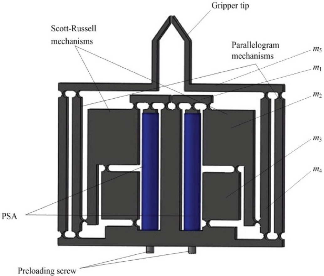
CAD model of a compliant gripper driven by two piezoelectric stack actuators (PSA)
The gripper structure consists of two SR mechanisms, which are used to amplify the PSA stroke. The role of the two parallelogram mechanisms is to guide a pure translational motion of the two gripper tips. Moreover, a second-stage lever is added between the SR mechanism and the parallelogram mechanism to further amplify the displacement of each gripper arm. It is observed that the PSA is embedded within the gripper structure, which leads to a full use of the in-plane space and results in a compact size of the gripper dimension.
In this work, the flexure hinges are adopted as right-circular shapes. As illustrated in Figure 2, each flexure hinge can be considered as a revolute joint in combination with a torsional spring. As compared with other shapes, the right-circular hinge allows the achievement of the lower centre shift of the revolute joints. Based on the pseudo-rigid-body (PRB) model of the flexure mechanism, the displacement and stiffness model of the gripper mechanism are established as follows.

PRB model of right-circular flexure hinge
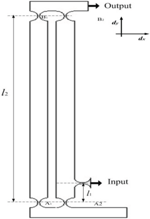
Scott-Russell mechanism: The schematic of a flexure hinge-based Scott-Russell mechanism is depicted in Figure 3. It is shown that O is a fixed pin joint, A is the input point to be driven by a PSA, and B is the output point.

Schematic of a Scott-Russell mechanism using flexure hinges
Let

where y A is the y-axis coordinate of point A.
Regarding a Scott-Russell mechanism under the condition of

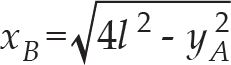
Solving (3) gives the expression of
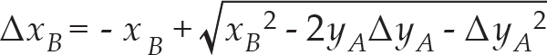
which indicates a nonlinear relationship between Δx B and Δy A .
As Δy
A
approaches zero, i.e.,

which is derived in view of (1).
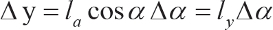
From (5), it is found that a small displacement Δy A along the y-axis will produce an amplified displacement Δx B = − Δy A cot θ along the x-axis if 0<θ < π/4. The negative sign means that a decreased Δy A will cause an increased Δy B . Therefore, the Scott-Russell mechanism can be considered as a straight-line amplifying mechanism with a fixed amplification ratio in the case of small-motion applications.
Lever mechanism: The second-stage lever mechanism is depicted in Figure 4. It can be seen that the amplification ratio is
Parameters of the second-stage lever mechanism

Therefore, the input-output displacement model of the gripper can be derived in consideration of (5) and (6):

which describes the ratio between the output and input displacements of the gripper tip.
Given the input displacements (q1 and q2) of the two PSA actuators, the gripper output motion (d x1 and d x2 ) and actuator input forces (Fin1 and Fin1) can be calculated by the following kinematics and static sequations:


where A s is the amplification ratio of the displacement amplifier; and K in is the input or actuation stiffness of the gripper structure.
Through the aforementioned relations, the kinematics and statics problems are converted into the calculation of the amplification ratio and input stiffness of the structure, respectively. In this paper, a pseudo-rigid body (PRB) model of the structure is established by considering each flexure hinge as a 1-DOF revolute joint combined with a torsional spring with stiffness K r . The stiffness equation of K r with the best accuracy, as compared in [19], is adopted for calculation. Let F x , Δx and Δy be the input force, input and output displacements, respectively.
First, only the compliances of the flexure hinges are considered in the PRB model. That is, it is assumed that each flexure hinge has 1-DOF rotational compliance arising from the rotational deformation, and other elements are all considered as rigid bodies.
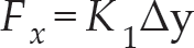
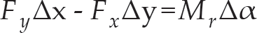
The free-body diagram of one amplifier leg is shown in Figure 4 and Figure 5. Under the equilibrium status, the equation of moments at point A 1 can be derived as follows:

PRB model of the displacement amplifier and its parameters

with the moment

where K r and Δα denote the rotational stiffness and deformation of a notch hinge, respectively.
Differentiating both sides of the displacement relation l x = l a sin α (where l x and α are variable during the operation) with respect to time allows the generation of
The translational stiffness K1 of the compound parallelogram is contributed by the rotational stiffness of the four notch hinges, which can be calculated below based on the potential energy analysis

where l2 denotes the length of the limb leg as shown in Figure 4. Thus, the force F x can be expressed as
Substituting (11), (12), (13) and (14) into (10) gives a relation between the variables F x and Δα as follows:

Moreover, in view of the virtual work principle, an equation can be obtained
which implies that the work done by external forces is equal to that done by internal forces.
Inserting (11), (12), (14) and (15) into (16) leads to a relation of Fx and Δx alone, which further gives
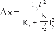
In addition, the input stiffness can be calculated by (17)

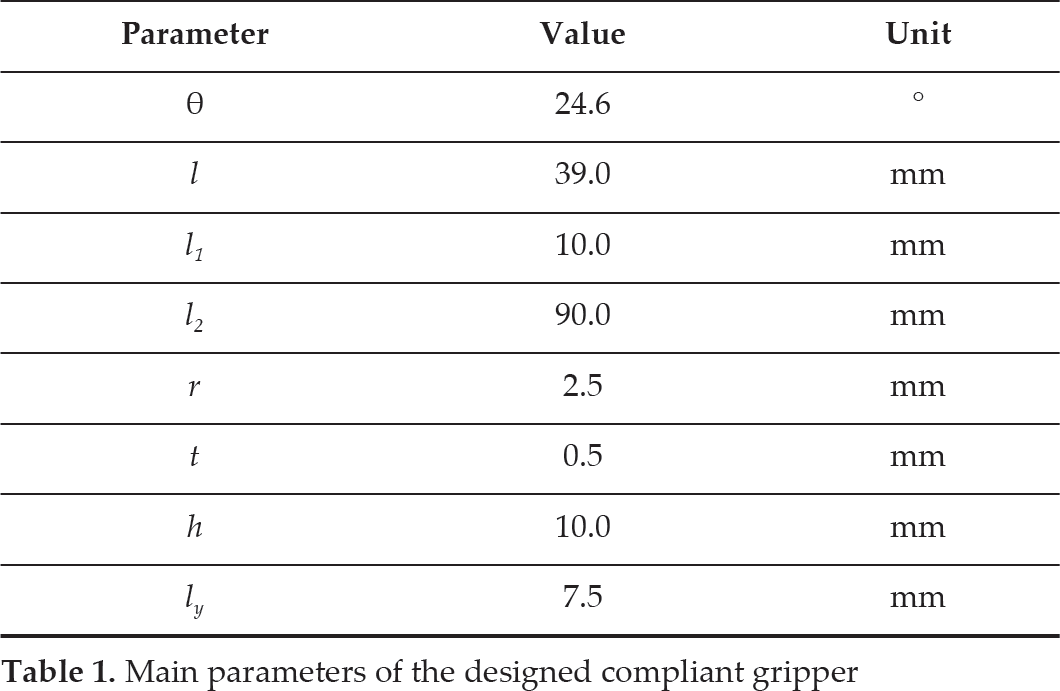
In this work, the main parameters of the designed compliant gripper are designed as shown in Table 1.
Main parameters of the designed compliant gripper
Stiffness and compliance analysis
The in-plane stiffness (K
x
) of the gripper structure relates the in-plane external forces (F
x
) applied on the gripper to the induced deflections (t
x
). By contrast, as the inverse of stiffness, the compliance

The compliance factor characterizes the output compliance (or output stiffness) of the structure suffering from external load.
Due to the symmetry of the left and right arms of the gripper structure, it can be deduced that Cx1 = Cx2 = C x in theory. In what follows, the output compliance C x of the stage is derived with an x−axis external force F x applied on the output platform.

The potential energies of the structure arise from the elastic deformations of the material, and are stored in the two limbs, which can be expressed in two different ways:

where Kx is the output stiffness of the stage in x−axis direction, and Kr represents the rotational stiffness of each flexure hinge around the working axis.
Inserting (20) into (21) gives an expression for the output stiffness

which implies that the output compliance is

The in-plane load capacity
For the in-plane operation, only the bending stress is taken into account to derive the load limit, because the axial tensile or compressive stress of the flexure hinge is far less than the maximum bending stress. For a flexure hinge bearing a bending moment around its rotation axis, the maximum angular displacement θ max occurs when the maximum stress σ max , which occurs at the outermost surface of the thinnest portion of the hinge, reaches the yield stress σ y .
The relationship between the maximum bending stress and the maximum rotational deformation of the flexure hinge has been derived [20]:
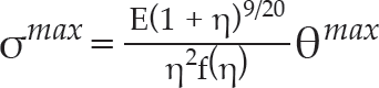
where η=

Flexure hinges rotate with the same angle

where

which allows the derivation of

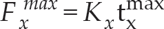
Once the maximum deflection is generated earlier, the maximum in-plane load that can be supported by the structure is given by
For the structure, considering the kinematics relation in (1), the coordinate vector of
Substituting the kinetic and potential energies into La-grange's equation

with i = 1 and 2, allows the generation of the dynamic equation describing a free motion of the stage

where the 2 × 2 equivalent mass and stiffness matrices take on the diagonal forms


where the masses m1 to m5 are denoted in Figure 1.
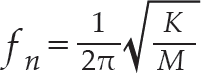
Therefore, the in-plane resonance frequency of the stage can be obtained as
As a case study, an SR-based compliant gripper is designed with parameters as tabulated in Table 1. The material is chosen as Al-7075 alloy, its modular of elasticity is E = 7.1 × 10¹¹ Pa, Poisson's ratio μ = 0.31, density ρ = 2810kg/m3, and yield strength [σ]=524MPa. The PSA is selected as model P-840.30 from Physikinstrumente (PI) Gmbh & Co. KG. The actuator possesses a length of 68 mm, and provides a stroke of 45 μm and maximum pushing force of 1000 N. The kinematic model (7) predicts that the ratio between the output and input displacements are A s = 13.1.
Static FEA simulation
First, the static structural FEA simulation has been carried out by applying an input force of 1 Non the input end of the gripper. The simulation result of the deformed shape is shown in Figure 6(a). After extracting the displacement values, the ratio between the output and input displacement is calculated as A s = 12.6.
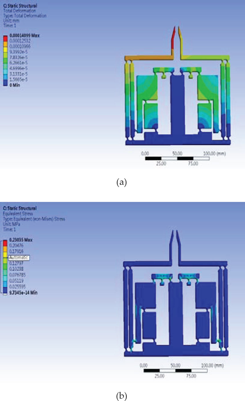
Static FEA simulation results, (a) Deformed shape; (b) stress distribution
As compared with the FEA result, the kinematic model overestimates 3.98% of the amplification ratio. The reason why the FEA result for the ratio is lower than that assessed by the analytical model arises from the deformations of the links between the flexure hinges. Only the bending deformations of the hinges are considered in the PRB model of the kinematic analysis, whereas other deformations exist as observed from the simulation results. Hence, a nonlinear modelling with consideration of all the deformations of the gripper mechanism will enhance the kinematic model's accuracy.
Additionally, the distribution of the equivalent stress is shown in Figure 6(b). It is observed that the maximum stress occurs at the hinge which links the SR mechanism and the lever mechanism.
Furthermore, modal FEA simulation has been conducted to examine the resonant mode frequencies and shapes of the gripper structure. The first six resonant mode shapes are shown in Figure 7, and the corresponding resonant frequencies are described in Table 2. It is seen that the first resonant mode at 102.74 Hz is attributed to the translation of the two parallelogram mechanisms along the same direction. The second mode at 107.12 Hz is contributed by the translation of the two parallelograms in opposite directions, which corresponds to the closing/opening working mode of the gripper tips. The third to fifth modes are caused by the out-of-plane deformations of the structure, while the sixth mode is induced by the in-plane bending deformation of one gripper arm.
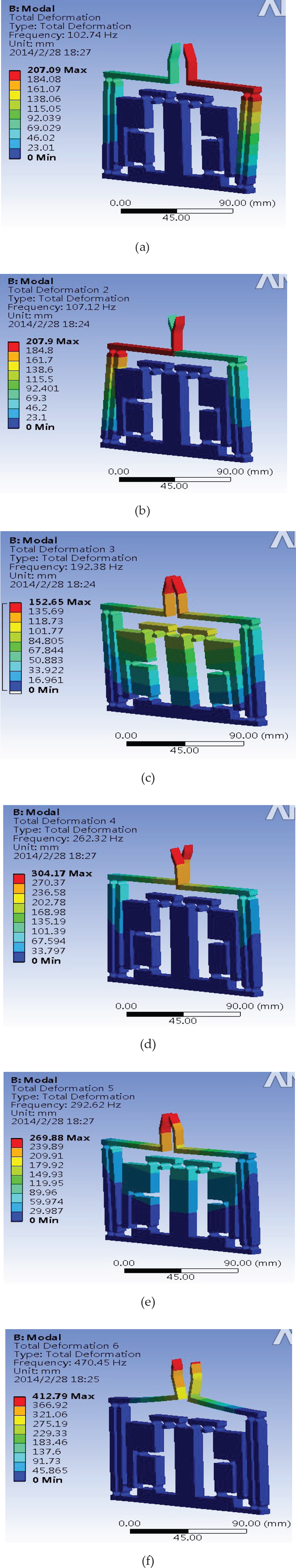
FEA simulation results of the first six mode shapes for the compliant gripper structure
The first six mode frequencies of the compliant gripper

The resonance frequency calculated by the dynamic model (34) is 108.83Hz. As compared to the FEA result, the dynamic model overestimates the resonance frequency with a deviation less than 6%, which validates the effectiveness of the derived model. It is observed from (34) that the resonance frequency of the structure can be magnified by increasing the input stiffness or reducing the equivalent mass of the stage. For instance, the material with a thinner thickness can be used for fabrication, and unnecessary mass of the moving parts can be removed to achieve a higher resonance frequency.
Experimental setup
In this section, a fabricated prototype of the gripper structure is presented and preliminary open-loop testing is conducted to demonstrate the gripper performance.
A prototype microgripper is fabricated, which is graphically shown in Figure 8. The mechanism of the stage is fabricated by the wire-cutting process from Al-7075 alloy. Concerning the actuation, two 45μm-stroke PSAs (model P-840.3 produced by Physikinstrumente Co., Ltd., see Table 3) are adopted to drive the stage. D/A board (NI-9215 DAC module) is employed to produce analogue voltages, which are then amplified by three-axis voltage amplifiers (model E-503.00 from PI GmbH&Co. KG.) to provide voltages of 0–100 V for the drives of the PSAs. In order to measure the output displacements of the moving platform, a laser displacement sensor (LK-H055, from Keyence Corp.) is used. The analogue voltage outputs of the sensor signal conditioners are read simultaneously by a personal computer through a data acquisition (DAQ) board (NI-9263 ADC module). They are programmed using LABVIEW software and downloaded to a controller (NI cRIO-9022) to realize the real-time control, as shown in Figure 9.

Prototype of the developed gripper
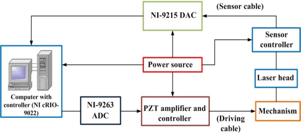
Hardware connection scheme
Specifications of the PSA actuator

In addition, each actuator is inserted into the mechanical amplifier and preloaded through the screw mounted at the tip of the actuator. This produces interference fits between the PSA and amplifier. Thus, no clearances exist during the operation due to elastic deformations of the material.
First, the open-loop static properties of the structure are experimentally tested. A low-frequency 0.1 Hz sinusoidal voltage signal ranging from 0 to 10 V is provided, which is then amplified by the voltage amplifier and used to drive the PSA 1. With the open-loop voltage-driven strategy, the PSA exhibits nonlinearity which is mainly attributed to the hysteresis effects.
The hysteresis effect of the PSA influences the mechanism's motion accuracy. With different rates of input voltage signal to PSA 1, the dominant hysteresis loops for the x-axis motion are shown in Figure 10, which shows that the gripping range of each gripper tip is about 1000 μm. Similar results can be obtained when PSA 2 is driven.
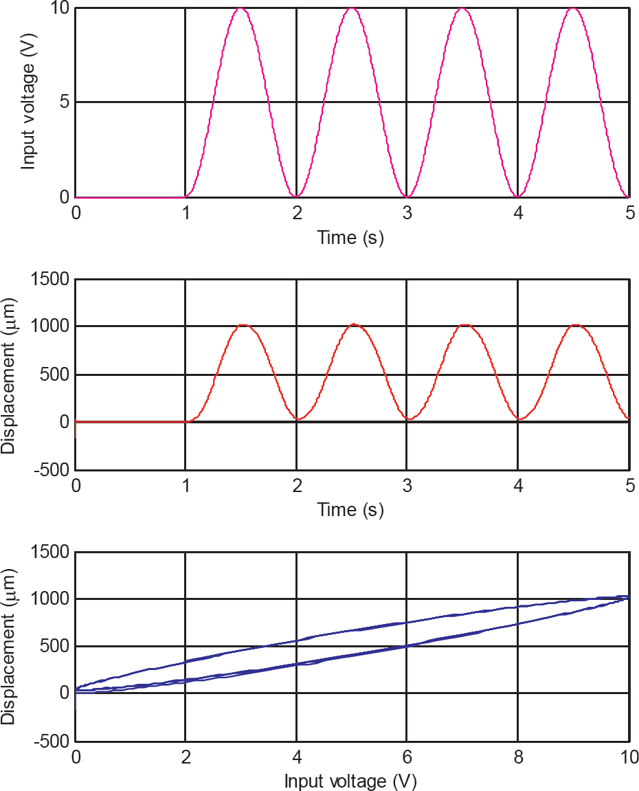
The output displacement and hysteresis characteristics of the gripper when PSA 1 is actuated with 1-Hz signal
In view of the stroke (45 μm) of the PSA, the amplification ratio of the stage can be determined as 22.2, which is larger than the FEA result. The reason for this is mainly the preloading effect of the PSA mounting. Because the two PSAs are inserted into the two mechanical amplifiers and preloaded using the screws, the preloading influences both the input displacement of PSA and the architecture parameters of the flexure mechanism. Since the PSA is inserted into the mechanical amplifier and preloaded using an adjusting screw, shown in Figure 8, the initial values for the parameters are changed. This produces interference fits between the PSA and amplifier. Hence, the ratio is greater than the nominal value.
In addition, the frequency response of the gripper is generated by a swept-sine approach. From Figure 11, it is found that the natural frequency of the mechanism is about 70 Hz, which is smaller than the FEA result. The reason is that the two PSAs increase the mass of the mechanism.

Bode diagram of the model with varioussampling times
The conducted experimental studies verified the feasibility of the proposed gripper design based on the SR mechanism. The accuracy of the kinematic model can be enhanced by considering all of the deformations of the structure. Besides this, the resonant frequency of 70 Hz may be increased by implementing an optimal design of the stage parameters.
In addition, the gripper can also be designed using multiple tips, as illustrated in Figure 12. It is found that the three tips of the gripper are driven separately to grasp the micro-object, which renders a more dexterous and reliable micromanipulation operation. By employing one gripper arm as a basic module, a modular gripper can be easily developed using more gripper tips.

CAD model of a modular compliant gripper with the three tips driven separately
In order to realize a microscale positioning, the piezoelectric hysteresis effects will be compensated by a controller. Both the error sources and piezoelectric hysteresis affect the open-loop positioning accuracy of the micropositioning stage. In future work, a controller design should be carried out to remedy the above shortcomings in order to realize a microscale manipulation.
Furthermore, in targeting a micromanipulation and microassembly application, a force control of the gripper tips is crucial to guarantee a safe gripping of fragile objects [8, 19]. In the future, force sensors will be employed to measure the grasp force of the gripper, and position/force control will be implemented to realize an appropriate position and force control strategy. The feasibility of the proposed gripper will be demonstrated by gripping different objects with controlled grasp force.
A new compliant gripper based on a Scott-Russell mechanism is proposed in this paper to amplify the PSA input displacement and to achieve a parallel motion of the gripper tips. An analytical model is established to facilitate the design of gripping range, and the model is verified with finite element analysis. Simulation results reveal that the gripper arms allow a pure translational motion. In addition, the gripper structure possesses a high resonance frequency which enables a rapid response. A prototype has been fabricated and experimental investigations have been performed accordingly. In comparison with traditional microgrippers, the proposed Scott-Russell based gripper allows the generation of a simpler structure. A compact dimension is achieved since the in-plane area has been fully used. It is found that the developed gripper exhibits a resonance frequency of 70 Hz and a large displacement amplification ratio of 22.2. In the future, force sensing/control will be realized to guarantee a desired microhandling of fragile objects in subsequent work.
Footnotes
9.
The work was supported by the Macao Science and Technology Development Fund under Grant No.: 070/2012/A3 and the Research Committee of the University of Macau under Grant Nos.: MYRG083(L1-Y2)-FST12-XQS and MYRG078 (Y1-L2)-FST13-XQS.