
Abstract
In order to solve the last centimeter problem of automated production, it is necessary to innovative design of flexible fixture. This article presents a metamorphic hand design method through the principle of metamorphic mechanism. Firstly, kinematic chain satisfying the requirements is obtained by number synthesis and structural synthesis. Then, the kinematic chain becomes a mechanism that meets the requirements using regeneration design rules. And the holographic matrix description method is used to describe the configuration transformation of the metamorphic mechanism. Furthermore, through the combination method of kinematic chain, the metamorphic clamp increases the two joint fingers into a metamorphic hand. Finally, the validity of the theoretical method is verified by physical experiments.
Introduction
Since the robot hand appeared, it has greatly compensated for the shortcomings of the traditional end-effectors. The end-effector is a device that directly performs the work, which has a great influence on the expansion of the robot’s operating functions, application scope, and efficiency. Therefore, it is very important to study the structural analysis of various end actuators of robots. In the conventional robot design, the palm is usually a rigid body. The angle between the different fingers is fixed, which limits the dexterity of some hands. The principle of metamorphic mechanism is used to solve this problem effectively. Metamorphic mechanism 1 –3 has many characteristics such as multi-topology change, which can be self-reorganized and reconstructed. Metamorphic mechanism changes configuration in the work process to adapt to different work.
Several multi-finger systems that work like the human hand, and even consist of human prostheses have been developed. For example, a new anthropomorphic finger mechanism is presented by Azlan and Yamaura. 4 It is able to perform both pinching and self-adaptive grasping operations. And Dai introduces a novel multifingered hand, known as Matahand. This robotic hand has a foldable and flexible palm that makes the hand adaptable and reconfigurable. 5 –10 From the research work of Nicolas Rojas et al., a two-fingered gripper topology is presented that enables an enhanced predefined in-hand manipulation primitive controlled without knowing the size, shape, or other particulars of the grasped object. 11 Similarly, Marco Ceccarelli et al. present the design of a new low-cost, easy operation hand, 12 and a gripper for horticulture product grasping is designed by Russo et al. 13 After these studies, some innovative ideas are applied in gripper. A novel spherical gripper mechanism with one degree of freedom (DOF) was designed. 14 Moreover, Lee and Wu describe an innovative robotic gripper a three-phalanx underactuated finger is embedded in the gripper. 15 To meet the need for processing small and delicate objects, compliant grippers have been developed. 16,17 However, the elastic deformation of compliant grippers is relatively large. It is not applicable to large and heavy objects.
This article presents a new innovative design of metamorphic gripper mechanism. Analyzing the requirements of the robot gripper, the mechanism requires 2-DOF. When designing the metamorphic hand, kinematic chains are obtained by number synthesis and structural synthesis. Then, the kinematic chain becomes a mechanism using regeneration design rules. And according to the performance evaluation factors, the appropriate kinematic chain is selected. In order to facilitate the description of the configuration transformation of the metamorphic mechanism, this article uses the holographic matrix method to describe. Through the idea of the kinematic chain combination method, the mechanical gripper increases the two joint fingers into a metamorphic hand. It achieves a different size, irregular objects grasp. Finally, the validity of the theoretical method is verified by physical experiments.
Gripper design
Aim of the study
Among robot assembly system, the design of the end-effector for reducing the error and the cycle is very important. This part contacts with the physical environment directly. Although the usual work errors can be attributed to many aspects, the problem often occurs at the end-effector. Well-designed manipulator end clamps can improve efficiency to a large extent, improve system reliability, compensate robot errors, and bring high added value to assembly systems.
When the gripper is clamping, the left and right clamps can move to the workpiece. As the workpiece is placed with a large error, the location of the workpiece may deviate from the center. When a clamp hits the workpiece and stops moving, the other clamp keeps on moving. When the two clamps touch the workpiece, the workpiece is clamped as shown in Figure 1. In this process, we can conclude that the DOF of the kinematic chain is changed from 2 to 1 and then to 0. There are three configurations in the metamorphic hand mechanism. In order to ensure the same force on both sides, it is best to use a driving link as input.

Workpiece gripping schematic.
The structural synthesis of kinematic chain
The total number of links in the mechanism that contains the rack is N. The number of active links is n = N − 1. The number of revolute pairs is J. The formula of DOF is as follows

According to the principle of mechanism, it can be understood that the multi-loop kinematic chain is formed by adding an Assur group on a single loop n = p. Each additional of a class II group N = 2 and J = 3 will adds a loop. Each additional a class III group or IV group n = 4 and J = 6 that adds two loops. The kinematic loop L is calculated as follows

By the formula (1) and formula (2), the following can be obtained

The DOF of clamp is F = 2. Since N and p are integers, the combination of N, p, and L can be calculated. In the kinematic chain, the link assortment array of an N-link F-DOF kinematic chain is denoted by [N2, N3, N4 … Np], where [N2, N3, N4 … Np], respectively, denote the number of binary, ternary, quaternary, and so on links. The highest connectivity p of a non-fractionated kinematic chain satisfied

When there is no composite hinge in the kinematic chain, i element link has i kinematic pairs. The kinematic pairs of the closed kinematic chain are all repeated, so there are

The results of number synthesis obtained are shown in Table 1. The results of structural synthesis are shown in the works of Ding et al. 18
Number synthesis table (DOFs F = 2).
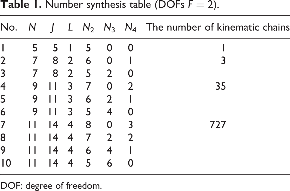
DOF: degree of freedom.
The five-bar and seven-bar kinematic chains are selected as the analysis object. The kinematic chain diagram is shown in Figure 2. The kinematic chain A is a five-bar mechanism. The kinematic chains B and C are seven-bar mechanisms. Among them, the kinematic chain B is a separable kinematic chain, which does not participate in the structural synthesis.

The kinematic chain diagram.
According to 2-DOF and both sides of the gripping requirements, the selected kinematic chain is symmetrical. The kinematic chain C-3 is selected as the clamp mechanism.
Figure 3(a) shows the selected seven-link 2-DOF kinematic chain. The ternary link 1 is selected as the rack. The binary link 2 is selected as the driving link. Two-DOF metamorphic clamp is designed as shown in Figure 3(b), where links 8 to 11 are virtual constraints. When calculating the DOF of the mechanism, the links that make up the virtual constraints with the kinematic pairs are all removed.

The clamp mechanism diagram. (a) Seven-link 2-DOF kinematic chain and (b) 2-DOF mechanical clamp. DOF: degree of freedom.
The configuration transformation of the metamorphic mechanism
The variable configuration of metamorphic clamp in Figure 3(b) is described. The topology changes are shown Figure 4. In configuration 1, the DOF of the metamorphic clamp mechanism is 2 as shown in Figure 4(a). In configuration 2, links 4 and 5 are fixed to the frame and become a single DOF mechanism as shown in Figure 4(b). In configuration 3, links 6 and 7 are also fixed to the frame, and the DOF of the mechanism becomes zero.

The topology graph of seven-link metamorphic mechanism. (a) Configuration 1, (b) configuration 2, and (c) configuration 3.
When using a computer to simulate a mechanism, it is only necessary to know the coordinates of the key points (the connection point of the two links, which may correspond to a plurality of kinematic pairs) in the mechanisms. Therefore, all the structural information of the mechanisms is known and schematic diagram of the mechanism can be drawn. Based on this idea, a holographic matrix was proposed. The size of the matrix is np × np. np is the number of key points of the kinematic chain. If there are no multiple joints, the number of kinematic chains is the same as the key points. If multiple joints are existed, the number of key points is less than the number of kinematic chains. The holographic matrix in configuration m is expressed as follows

where the diagonal element of the matrix Ji represents the elements of the kinematic chain connecting two adjacent links in key point i. Such as prismatic pair P, revolute pair R, spherical pair S, and so on. The upper off-diagonal element li,j(i<j) denotes the distance between two key points, which is the length of the two key points on the link corresponding to the link number in the lower triangular matrix. If the link is multiple links, it is the length of the two key points. If there is no actual link exists between key points i and j, then li,j = 0. The lower off-diagonal element ai,j(i>j) is the serial number of the link between key points i and j in the mechanism. Due to there may be multiple links in the kinematic chain of the mechanism, so that multiple elements may have the same value in the lower left triangular matrix element. If there is no actual link exists between key points i and j, then ai,j = 0.
The k + 1 column element of expanded whole matrix includes the serial number of the frame link and driving link. The value of the other element is “0.” The k + 2 column element includes initial position (initial angle)sλ, stop position (stop angle)sμ, velocity (angular velocity)ν, and accelerated velocity (angular accelerated velocity)α. And the information of kinematic pair can be known by searching the holographic matrix. In order to better record the sequence of the transformation, a row is added to the expanded holographic matrix. The element
The holographic matrix contains not only the connection of the kinematic chain, but also includes links length, pairs attributes, frame, driving link, and driving link attribute information. The holographic matrix shown in equation (6) is used to represent the various configurations of the seven-link metamorphic mechanism in Figure 4.


The original metamorphic mechanism is able to evolve into any configuration of the mechanism and contains all the topological elements found in all configurations. An original matrix

Metamorphic hand
Due to the irregular shape of the workpiece, the two clips are very limited. Therefore, through the idea of the kinematic chain combination method, the metamorphic clamp increases the two joint fingers into a metamorphic hand. Finger often designed into two joints, middle finger, and fingertips, but also has 2-DOF. So the selection of the mechanism requires synthesis data of the kinematic chain in “Gripper design” section.
Finger joints have characteristics middle finger and fingertip independent movement. According to the idea of regenerative design, the kinematic chain conversion mechanism is as follows: Step 1: Determine the rack. The movement of the fingertips requires an independent loop in the kinematic chain. Therefore, when selecting a rack, an independent loop needs to be retained. Step 2: Selecting driving link. The driving link needs to be in the adjacent link of the rack and cannot appear in the independent loop of the fingertips. Step 3: Determine executive link. Since the finger is 2-DOF, there are two execution members. The middle finger is selected as an adjacent link to the rack. The fingertip execution link is opposed to the middle finger in an independent loop.
The kinematic chains are regenerative designed according to the above rules as shown in Figure 5.

Mechanism scheme. Gr: the rack; d: the driving link; a: the fingertip execution link; and b: the middle finger execution link.
Evaluate the scheme. The independent loop in kinematic chain C-3 is five-bar mechanism in which optimization design is more complex. The fingertip execution link of the kinematic chain C-2 is a multi-link. Fingertip transmission force is lacking. So this article selected kinematic chain C-1 as the finger joint mechanism. Link 1 is rack, link 2 is driving link, link 5 is middle finger execution link, and link 6 is fingertip execution link.
A seven-link 2-DOF mechanism is selected as finger joint as shown in Figure 6(b). The metamorphic clamp is combined with the mechanical finger joint. A novel metamorphic hand is obtained as shown in Figure 7.

Mechanical finger joint diagram. (a) Seven-link 2-DOF kinematic chain and (b) 2-DOF mechanical finger. DOF: degree of freedom.
A metamorphic hand diagram.
The metamorphic hand consists of a 2-DOF clamp and two 2-DOF fingers. When the three seven-bar kinematic chains are combined, there are common members such as links 5 and 7, while the frame is shared by two members, so the number of components is 17. At the same time, the frame merges eliminating two links. So the link number of the metamorphic hand is
The process of grabbing is divided into five configurations as shown in Table 2. In configuration 1, the two middle fingers can move. The fingertip is fixed on the middle fingers. In configuration 2, when a middle finger touches workpiece, only one middle finger move. In configuration 3, the two middle fingers touch workpiece. A fingertip begins to move until contact with workpiece. In configuration 4, another fingertip move alone. In configuration 5, the workpiece is grasped.
The configuration transformation table.a

DOF: degree of freedom.
a−1 represents that the kinematic pair is fixed.
The original matrix A(0) for representing the metamorphic hand mechanism is

In equation (11), the first box is a 2-DOF metamorphic clamp holographic matrix, the second box is the 2-DOF up finger holographic matrix, and the third box is the 2-DOF down finger holographic matrix. The original matrix contains five kinds of structural transformation information and contains the structural information of the mechanism.
Experiment
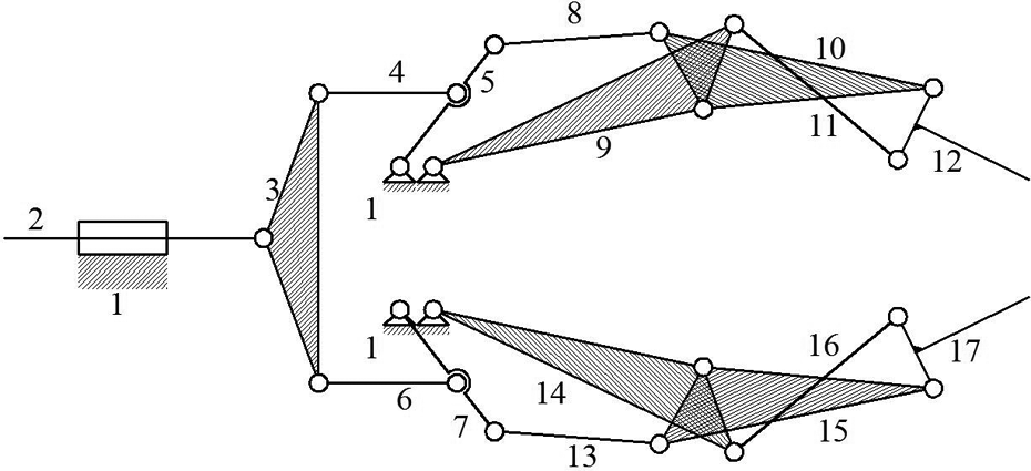
Solidworks 2016 software was used to design the structure of the metamorphic hand mechanism. Considering the order of joint movement, the drive angle of fingertip joint is designed as small as possible. The prototype of metamorphic hand is shown in Figure 8.

Prototype of metamorphic hand.
The serial number in the figure is the serial number of the execution link. Link 12 is a left-hand fingertip, link 9 is the left-hand middle finger, link 17 is a right-hand fingertip, and link 14 is the right-hand middle finger. The structure parameters of metamorphic hand are shown in Table 3.
Structure parameter of metamorphic hand.

Grasping the round box is used as an example to support the configuration transformation of metamorphic hand as shown in Figure 9. The outside diameter of the box is 110 mm and the height is 50 mm. The black dots in the mechanism diagram represent the kinematic pair fixed.

The process of prototype grabbing. (a) Configuration 1, (b) configuration 2, (c) configuration 3, (d) configuration 4, and (e) configuration 5.
The distance center maximum working range between the metamorphic hand and round box is about −26 mm to +26 mm. The relationship between the moving distance of the slider 2 and the angle of each links during the grasping process is shown in Figure 10.

The links angle of grasping.
The angle of link 3 is 7° when the center distance is 6 mm, as shown in Figure 10. For further experiments, the entire grasping process is recorded by a fixed camera. The captured objects contain different shapes shown in Figure 11.

Objects with different shapes. (a) Cylinder, (b) cuboid, (c) hexagonal prisms, (d) triangular prism, and (e) sphere.
The distance center maximum working range is about −30 mm to +30 mm. Analysis of the metamorphic hand performance in different shapes is shown in Figure 12.

The link 3 angle change grasping different shapes objects.
The change trend of link 3 angle in different shapes is the same shown in Figure 12. And the average angular range fluctuation is 1.57°. In order to further study the adaptability of the variable hand, the prototype metamorphic hand grasps objects in life, including square box, trapezoidal object, mouse, triangular workpiece, L-shaped components, and so on, as shown in Figure 13.

Grasping irregular objects.
It is easier for the metamorphic hand to grip the rules regular objects as shown Figure 10(a), (g), and (h). When metamorphic hand grips the irregular objects or smaller object as shown Figure 10(b) to (f), the angle of the objects is required. Experiments show that the requirements of metamorphic hand grabbed objects are basically realized. The movement process also conforms to the design requirement the DOF from 2 to 1 and then to 0.
Conclusions
A new innovative design of metamorphic gripper mechanism is proposed. The number synthesis and structural synthesis of kinematic chain are the source of thought. This can be achieved from scratch design. A variety of mechanisms are obtained by regeneration design. And the holographic matrix is used to describe the configuration transformation of the metamorphic mechanism. The information on link size, driving link properties and rack properties in holographic matrices is very helpful for kinematics analysis. The prototype of metamorphic hand grasps a different size, irregular objects. The validity of the theoretical method is verified by physical experiments. And the metamorphic hand performs a quick gripping test in the actual production line for further process.
Footnotes
Declaration of conflicting interests
The author(s) declared no potential conflicts of interest with respect to the research, authorship, and/or publication of this article.
Funding
The author(s) received no financial support for the research, authorship, and/or publication of this article.