
Abstract
We introduce a novel visual-assisted relocalization method for autonomous robots, enhancing both indoor and outdoor navigation. Recognizing the limitations of relying solely on light detection and ranging (LiDAR) sensors for simultaneous localization and mapping (SLAM), our approach integrates visual sensors to complement existing LiDAR-based systems without necessitating a complete overhaul. The proposed relocalization strategy, which treats both point and object features in image frames as scene descriptions, can be seamlessly integrated with multiple indoor–outdoor LiDAR-based SLAM algorithms. Establishing a link between these features and the robot’s poses transforms them into natural landmarks. Via an efficient feature-matching procedure, initial pose estimates can be obtained and provided to the primary LiDAR-based relocalization scheme to compute final pose estimates. The novelty of our method lies in its flexible add-on design, its compatibility with various LiDAR-based SLAM algorithms, and its ability to significantly boost the robustness and adaptability of robotic navigation. Extensive experiments across diverse environments confirm the performance superiority of the proposed strategy, demonstrating its practical value for real-world applications.
Introduction
In the field of autonomous mobile robotics, accurate localization is essential for reliable navigation.1–5 Over recent decades, the use of light detection and ranging (LiDAR) for simultaneous localization and mapping (SLAM) has become a prominent research focus.6–8 This has led to the development of several effective, open-source LiDAR SLAM algorithms and software frameworks. Notable examples include Google’s Cartographer for two-dimensional (2D) LiDAR sensors, 7 LIO-SAM, 6 which couples a three-dimensional (3D) LiDAR sensor with an inertial measurement unit (IMU), and the FAST-LIO2 algorithm 9 as a representative of promising filter-based schemes. These tools and approaches have made it easier to implement LiDAR-based robot navigation systems, making LiDAR, especially 2D LiDAR sensors, the standard for mapping and localization in most indoor robot products.
However, LiDAR-based SLAM schemes have some limitations. They may struggle to map large structure-less open areas and can fail to determine the robot’s position as it starts up at a random spot in the scene. To overcome these issues, researchers have begun to turn to visual sensors mounted on the robot as well for supplementary support in LiDAR-based localization endeavors. Visual sensors offer a more detailed environmental capture compared to their LiDAR counterparts, thereby enhancing place recognition capabilities, especially in texture-rich settings. State-of-the-art visual solutions have often leveraged artificial landmarks, such as AprilTags or other fiducial markers,10–12 to enhance localization accuracy. But these require changes to the robot’s surroundings, adding to the cost and complexity. 13 The need for artificial landmarks also compromises the robot’s true autonomy.
On a different note, visual SLAM is gaining attention in research. Visual SLAM systems mainly fall into two categories: feature-based14–16 and direct methods.17–19 Combining visual and inertial data can improve the accuracy and robustness of SLAM, as seen in systems such as ORB-SLAM3, 16 the VINS series,20,21 and Kimera, 22 a multi-session mapping framework enabling the generation of 3D semantic maps of the environment. These advanced visual SLAM systems show the potential of visual sensors but are not yet mature enough for standalone localization in commercial robots.15,20 Their path to widespread industrial use is still being defined.
Having realized that a wise first step seems to be exploiting the advantages of visual sensors by using them as a supplement to the robot’s primary SLAM strategy in a smart manner, as a first attempt, we have proposed a novel visual-assisted relocalization scheme for indoor robots using LiDAR SLAM as the primary localization technique. 23 It can be regarded as a loose coupling of visual and LiDAR sensors, targeting at solving the critical issue of the loss of localization and enabling an effective global relocalization. The design principle is to completely avoid changing the robot’s operating scene by more thoroughly exploiting the contents of the image frames captured by the visual sensors.
In the meantime, we have reviewed several recently proposed multi-sensor fusion SLAM frameworks, such as optimization-based methods, LVI-SAM 24 and LVIO-SAM, 25 which combine LiDAR-inertial odometry (LIO) and visual-inertial odometry, and filter-based methods such as FAST-LIVO 26 as an extension of FAST-LIO 27 and FAST-LIO2. 9 In our attempt to implement and evaluate these schemes on robot products we have developed, we have found that although they show the SLAM community interesting and inspiring ideas about how visual, LiDAR, and inertial measurements can be more tightly coupled into a complete SLAM system, the performance of these schemes is not always satisfactory in complex real-world scenarios, especially when consumer-level sensors are used. Moreover, as there are specific requirements for the visual sensor types, existing visual sensors mounted on the robot might have to be replaced, and a hardware synchronization is required. On the other hand, it is common that the focus of SLAM algorithms in the literature is naturally on simultaneous mapping and localization, while in the engineering world, enabling relocalization with a previously established map is an indispensable capability of autonomous robots. The engineering adaptations, both software and hardware, required to achieve this are non-trivial.
Therefore, in this paper, we introduce the concept of a flexible and powerful visual-based add-on that can be coupled with multiple indoor–outdoor LiDAR-based SLAM algorithms and jointly contribute to enhanced and robust relocalization performance. It can be regarded as a mature engineering solution catering to the needs of commercial robot product development. The advantages of visual sensors and methods are fully exploited, while keeping the developing and testing cost of robot products that need to be iterated timely under control. To this end, we propose to exploit two types of visual features: point features and object features serving as a promising supplement to their point-based counterparts. By establishing a link between these visual features and the robot’s poses, we are able to transform them into natural landmarks contributing to a detailed description of the scenario. This eliminates the need for artificial markers, allowing the robot to leverage visual features within the environment for precise localization. During the relocalization procedure, initial pose estimates are derived through an effective feature-matching process and are subsequently utilized by the primary LiDAR-based SLAM system to determine the final pose estimates.
In pursuit of a robust relocalization strategy that is also promising in practical applications, we have introduced several enhancements to our framework. Acknowledging the dynamic nature of robotic operations, we have integrated an incremental mapping mode. This allows the system to update scene features in a timely manner as the environment evolves, ensuring that the feature matching-based relocalization remains effective. To address the limited field of view (FoV) inherent to a single-camera system, which restricts the capture of scene features, we have developed a multi-camera configuration. This setup extends the coverage of the visual sensors, providing a more comprehensive perception of the environment. In addition, we have formulated an autonomous mapping strategy. This strategy involves planning a mapping trajectory that adapts to a specific scenario, enabling the autonomous extraction of visual features. It is important to note that the proposed visual-assisted relocalization scheme has been successfully implemented in both indoor and outdoor robot products. The adaptability of this approach has been validated through extensive experimental evaluations and detailed analyses. The results demonstrate a high success rate across diverse scenarios, confirming the compatibility of our strategy with various indoor and outdoor LiDAR-based SLAM algorithms.
The major contributions beyond our previous conference paper
23
are as follows:
We introduce for the first time the concept of a visual relocalization add-on, as a mature and powerful standalone tool, and validate its capability of coupling with multiple LiDAR-based SLAM frameworks in various scenarios ranging from indoor to outdoor. We propose a more thorough and deeper exploration of the information captured by a visual sensor. In addition to point features that are known to suffer from many critical limitations of appearance-based visual methods, we propose to extract and make use of object features as well such that not only the appearance but also semantic information is exploited to further enhance the relocalization performance. To conform to the autonomous nature of our robot products and target a minimum product delivery and deployment effort, we propose an autonomous mapping concept and path planning schemes tailored for different scenarios. We conduct a thorough performance evaluation of the proposed visual-assisted relocalization add-on and present extensive experimental results in this paper covering a variety of aspects and scenarios ranging from indoor to outdoor, large-scale, or irregular, with changing illumination conditions that visual-based methods are known to be sensitive to. Numerous experiments have been designed and performed to analyze the performance of the proposed autonomous mapping strategy as well as the benefits and possible limitations of introducing object features. Through discussions of these results, recommendations and advice are provided for the parameter selection and scene settings.
The remainder of the paper is organized as follows: the main idea and the structure of the proposed visual-assisted relocalization strategy are first presented, followed by a detailed description of further extensions of this framework, where engineering considerations are taken into account. Finally, extensive experimental results are shown, before conclusions are drawn.
Main idea and proposed framework
The underlying principle of our proposed visual-assisted relocalization strategy is that the visual features, whether points or objects, captured in each image frame are capable of describing the corresponding scene. Concurrently, the robot’s pose at that moment is already known, for instance, through the LiDAR SLAM algorithm in operation. These visual features are then utilized as landmarks. For point features, a connection is established between the image frame’s point features and the robot’s corresponding pose, which is recorded. When the robot revisits a familiar scene, the previous image frame ID is retrieved through feature matching, providing an approximate pose estimate for the robot. Object features offer an enhanced description of the environment due to their rich semantic and geometric information. Initially, objects are detected and tracked across consecutive frames. Through a reconstruction process, the 3D positions of these objects are calculated and continuously refined. During relocalization, the semantic labels of object-based landmarks are key to identifying matches between the objects in the map and those observed currently. The perspective-three-point (P3P) algorithm is then employed to compute preliminary pose estimates, with the final pose estimate chosen based on an intersection-over-union (IoU) criterion. This pose estimate serves as an initial guess for the robot’s position, aiding the LiDAR-based relocalization scheme in achieving a more refined and precise positioning.

Block diagram of the proposed visual-assisted relocalization add-on consisting of the “Mapping” process and the “Relocalization” process corresponding to the left and right columns in dashed boxes, respectively; the “Point feature-based” version and “Object feature-based” version are illustrated in the blue and green boxes, respectively.
Figure 1 illustrates the proposed visual-assisted relocalization framework. It is worth noting that point feature extraction, object detection, and reconstruction are typical and indispensable steps that initiate the tracking procedure of a visual odometry or a visual SLAM scheme.16,22,28 Thanks to mature and advanced algorithms,29–31 point feature extraction, object detection, and reconstruction, which contribute to the majority of the computational effort of the proposed strategy, can be performed very efficiently, enabling a real-time processing. In fact, compared to existing visual SLAM methods16,22,28 and state-of-the-art multi-sensor fusion SLAM frameworks,24,25 as neither a complete tracking procedure nor an optimization step is required, the proposed strategy is even less computationally demanding.
With point features
As depicted in the blue box marked with “point feature-based” in Figure 1, the point feature-based version of the visual-assisted relocalization strategy consists of two processes, that is, the so-called “Mapping” process and the “Relocalization” process (cf. the left and right columns marked by dashed boxes in Figure 1, respectively). During the mapping stage, the robot captures image frames and identifies key feature points, generating descriptors and bag-of-words vectors to form keyframes. These keyframes, along with the robot’s associated poses, are stored to create a visual map. In the relocalization stage, the system references this map to identify the robot’s current position. It loads the visual map, detects feature points in new image frames, and performs feature matching using DBoW2 to find correspondences with the stored keyframes. The pose estimates from the matching keyframes serve as initial guesses, which are then used to compute a more refined final pose estimate. Given the well-recognized ability of ORB features to effectively capture scene details, the collection of matching keyframes is sorted according to their matching ORB feature count. Consequently, it is ensured that the keyframe featuring the greatest number of matching ORB features is the first to be considered by the main localization method. We refer interested readers to Cheng et al. 23 for detailed steps of this algorithm and an evaluation of the effectiveness of using the matching ORB feature number as a criterion to sort the matching keyframes. In addition, it is presented in Cheng et al. 23 that for a few critical scenes of representative robot operating areas, the ORB feature matching scheme is able to identify previously visited spots and is thus capable of providing an accurate and helpful initial pose estimate.
With object features
In parallel to or coupled with the point feature-based mapping and relocalization procedures, object features captured with the visual sensor can be exploited as well, as illustrated in the green box marked with “object feature-based” in Figure 1. As the image frames are coming in, in addition to the point feature extraction, objects are detected with state-of-the-art object detection approaches, for example, the YOLO network30,31 used in this paper. In the literature, objects have been modeled in a variety of forms such as cubes
32
and spheres.
33
Here we choose to use the ellipsoid–ellipse representation of objects, that is, objects are represented with ellipsoids, whereas their 2D observations in the images are modeled as ellipses.28,34,35 The reason is two-fold. First, only nine parameters are required in this light-weight representation of objects, three for the axes size, orientation, and position, respectively.
34
Second, the 3D–2D projection, that is, projecting an ellipsoid as an ellipse, can be conveniently written in an algebraic-closed form such that an ellipsoid, essentially a quadratic surface defined by a dual form

The detected objects of consecutive image frames are tracked based on their semantic labels and the overlapping of the detection boxes measured via the IoU as a common practice
36
for object tracking. Note that to enhance the robustness of tracking in critical situations due to, for example, fast camera motions and limited camera FoV, object reconstruction results can be taken into account in the data association procedure as well.
28
Objects that have been tracked in a certain number of image frames and viewed in different angles are then first represented as spheres, gradually refined and transformed into ellipsoids via an object reconstruction procedure.
28
The position of the reconstructed sphere as the initial form of an object and its radius are computed with the current robot pose and the information of the detection box, such as its center and size. In contrast to Zins et al.,
28
our scheme does not include a typical tracking procedure of a visual odometry where the robot pose is estimated. Instead, we directly make use of the more stable and accurate pose estimates of the primary LiDAR-based SLAM framework. Hence, our approach does not suffer from the widely known limitations of monocular visual odometry employed in Zins et al.,
28
contributing to satisfying object reconstruction results as illustrated in Figure 2. The resulting ellipsoid form of the object is constantly optimized by minimizing the reprojection error formulated in Zins et al.
28
based on the ellipse–ellipsoid transformation mentioned above in equation (1). When the mapping session is over, the established visual map holding all the object information including the ellipsoid forms of the objects and their semantic labels is saved. For relocalization, the aforementioned visual map is first loaded. Then objects detected in the current image frame are matched with those in the map, forming matching ellipse–ellipsoid, that is, 2D–3D matching pairs that can be used to compute rough pose estimates. Among all matching pairs, for every possible group of three pairs, four solutions of the pose estimate are obtained with the P3P algorithm.
28
Let us denote the number of matching ellipse–ellipsoid pairs as


Illustration of the object reconstruction results.

Illustration of the two-dimensional–three-dimensional (2D–3D) matching pairs and the grouping for the computation of pose estimates.

Evaluation of the effectiveness of using the IoU-based score as a criterion to select the pose estimate. (a) Plot of the absolute distance between the estimated position and the ground truth position as well as the corresponding IoU-based score and (b) CDF of the IoU-based score corresponding to a certain range of the absolute distance between the estimated position and the ground truth position. IoU: intersection-over-union; CDF: cumulative distribution function.
Here we evaluate the effectiveness of using this IoU-based score as a criterion to select the pose estimate in Figure 4. Indeed, as shown in Figure 4(a), when the score is low, indicating that with the current pose estimate, the IoU is high, that is, the reprojection of the 3D ellipsoid matches well with the detection box, the deviation of the pose estimate from the ground truth position is small, and the pose estimate is accurate. For a clearer visualization, we plot the results of Figure 4(a) additionally in Figure 4(b) where the cumulative distribution function (CDF) of the IoU-based score corresponding to a certain range of the deviation of the pose estimate from the ground truth position is presented. It can be seen that for a smaller discrepancy between the pose estimate and the real position, the corresponding IoU-based scores are lower, that is, they are distributed in the region of lower scores. For instance, as the pose estimates are about 0.2 m away from the ground truth position, the CDF of the corresponding IoU-based scores reaches 1 with respect to IoU-based scores of roughly 0.53, which implies that the IoU-based scores are all below 0.53. The scores are distributed in the range from 0.37 to 0.53. By contrast, for the case where the absolute distance between the estimated position and the ground truth position is about 0.6 m, the IoU-based scores are distributed in the range from 0.47 to 0.63.
Note that the object reconstruction scheme inspired by Zins et al. 28 and described above can be regarded as a nice derivative technique of the proposed visual-assisted relocalization add-on. It can be combined with a random odometry to build a map with object landmarks. By training an object detection model of selected objects, landmarks can be customized and tailored for certain scenarios as discussed in the section where numerical results are presented.
Engineering considerations and extensions
Our goal in designing this system is to create a promising and mature solution for visual-assisted relocalization that works well for robot products in a wide range of dynamic scenarios. To achieve this, we propose three important extensions to the framework we introduced earlier.
Incremental mapping and multi-camera mode
An incremental mapping mechanism and a multi-camera mode 23 are developed to guarantee a thorough and up-to-date coverage of the scene, which is crucial for effective relocalization in complex and dynamic scenarios. The incremental mapping strategy addresses environmental changes that can affect pose estimation accuracy over time. It involves periodically updating the visual map to reflect new scene features. When the robot detects significant changes, it incorporates these into the existing map through feature matching. This approach ensures the map remains representative of the current environment, thereby enhancing the reliability of the relocalization process. It also improves the system’s robustness under varying lighting conditions as shown in Cheng et al. 23
The proposed multi-camera mode of the visual-assisted relocalization strategy, on the other hand, leverages multiple cameras to expand the robot’s FoV and improve relocalization accuracy. By analyzing and fusing feature-matching results from different cameras, the system can identify a more accurate initial pose. This is particularly useful when the number of features extracted varies between cameras. Moreover, it has been found that the choice of cameras and their mounting positions are crucial. Based on a thorough investigation, we propose the following multi-camera setting: a forward-facing camera captures the scene from a human-like perspective, whereas an upward-facing camera is in charge of the part of the scenario with limited feature variation, for example, the ceiling or the upper part of the walls. It is shown that the use of multiple cameras, especially in challenging conditions such as sharp turns or areas with repetitive features, can significantly reduce pose deviation and enhance the overall success rate of relocalization. 23
Autonomous mapping
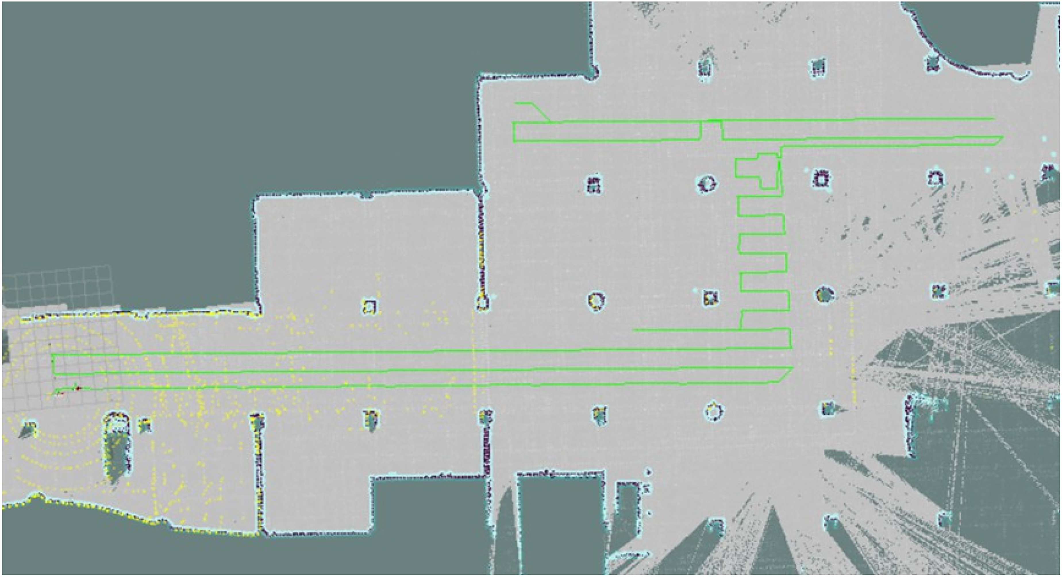
The mapping session is crucial for accurate pose estimation in the relocalization session. Capturing the scene features and covering the operation spots of the robotic device thoroughly is the goal. Mapping manually requires manpower, and the results might not be stable and reliable enough, as they highly depend on the experience and training level of the person setting the robot up and how he or she operates it. As a map for navigation is available, we propose an autonomous mapping strategy. For scenarios such as corridors where free space is limited and forms a clear path for a robotic device or outdoor scenes with specified lanes, the mapping trajectory can be straightforwardly planned along the path or the lane by providing the starting and ending points of the mapping session. This suffices to have the operating scene covered. In the case of open-area scenarios, for example, open-plan office space or a big hall, the operating area and trajectory of a robotic device are rather random. Targeting at these challenging scenarios, we resort to the coverage path planning (CPP) algorithms for mapping path planning.37,38 The CPP schemes are widely employed for cleaning robots, robot lawn mowers, and agriculture machines,39–41 etc., for which a complete scene coverage is an essential capability. In particular, a complete coverage path planning (CCPP) algorithm aims to determine a path through all spots in an area or a certain spatial range while avoiding obstacles. Based on a previously established grid-map of the area, a CCPP algorithm segments the area by expressing the environmental information in the grid unit and then plans the collision-free path such that a reciprocating motion of the robotic device is enabled. In this way, a full coverage of the scene is achieved, while repeated paths are avoided, guaranteeing high efficiency, as illustrated in Figure 5, where the widely known Boustrophedon algorithm 42 is employed.

Illustration of the mapping path planned based on a complete coverage path planning (CCPP) method.
The autonomous mapping strategy introduced above is proposed for relatively large open areas with a regular shape. On the other hand, for smaller open areas taking an irregular form, we propose the following path planning scheme: based on a previously established grid-map of the area, key points of the path are manually set in the driving order through, for example, a .json file, and a mapping path is obtained by connecting these key points sequentially as depicted in Figure 6. This approach can also be used in cases where the operating area and trajectory of the robotic device in an open-plan area are well-defined and fixed to accomplish certain tasks, for example, warehouse robots.

Illustration of path planning according to specified key path points.
Thanks to the autonomous mapping solutions presented in this section, the mapping session of the proposed visual-assisted relocalization scheme can be efficiently and effectively performed with little manpower and results in even better relocalization performance compared to the case of mapping manually as validated in the following section where extensive results are presented.
Detailed analysis and experimental results
To thoroughly assess the performance of the proposed visual-assisted relocalization add-on, we have successfully implemented it in an indoor tour-guide robot, a delivery robot, and an outdoor patrol robot that are designed and developed in our institute (cf. Figure 7). All experiments presented in this paper have been performed with these robot products in real-world indoor and outdoor scenarios.
The sensors equipped on the robots used for navigation include a 2D LiDAR sensor and a 3D LiDAR sensor for the indoor and outdoor robots, respectively, an odom, an IMU, and cameras as presented in Figure 7. The main processing unit for navigation is an x86 processor with an i5-10210U CPU at 1.60 GHz and an 8 GB memory.

The three robot products that we have developed and have been used in experiments presented in this section. (a) Illustration of the indoor tour-guide robot (left) and the indoor delivery robot (right) and (b) Illustration of the outdoor patrol robot.
The proposed add-on concept has been validated on the indoor and outdoor robots shown in Figure 7 with different primary LiDAR-based SLAM frameworks implemented. For the indoor robots, we use a modified version of Cartographer
7
as the LiDAR-based mapping and localization framework. Meanwhile, for the outdoor patrol robot, LIO-SAM
6
and the normal distributions transform (NDT) algorithm
43
are employed for mapping and relocalization, respectively. We have observed that at many randomly chosen spots in several indoor and outdoor scenarios, the relocalization using our proposed strategy was successful. This means that by using the initial pose estimate obtained via our visual-assisted relocalization add-on, the LiDAR-based relocalization schemes are able to provide an accurate final pose estimate of the robot. It was also verified that an initial pose estimate within roughly 5 m from the ground truth pose is usually sufficient for the aforementioned LiDAR-based relocalization schemes to compute an accurate final pose estimate. Initially, the relocalization function was started manually by identifying the robot’s position and drawing a
In the following, we concentrate on the “visual” part of our strategy, which is the core of the relocalization process, and evaluate its performance across diverse scenarios and conditions. Our primary metric for assessment is the absolute distance between the estimated pose and the ground truth pose, 23 with the results presented in the form of a CDF.
With point features
The performance of the proposed visual-assisted relocalization scheme with point features in indoor scenarios is thoroughly evaluated in Cheng et al. 23 It has been observed that our proposed relocalization strategy using point features exhibits high accuracy in confined areas such as corridors due to the robot’s consistent mapping route. In open-plan office scenarios, despite greater challenges in feature matching, the proposed scheme still achieves a high success rate. The introduction of a rotating mechanism and incremental mapping further improves the relocalization performance, especially in dynamic environments. In addition, the multi-camera mode, combining forward and upward views, significantly enhances success rates and reduces pose deviation even in challenging areas. Furthermore, we have investigated the influence of the ORB feature number per image frame as well as the frame rate and have provided guidance on the selection of these important parameters.
Next, we show how the proposed scheme performs in a large-scale outdoor scenario depicted in Figure 8 where the point-cloud map of the scene with the mapping trajectory marked blue is presented. A mapping round took place in the morning, whereas two relocalization sessions were performed for this experiment. One of them was scheduled on the same morning as the mapping session, while the other took place in the late afternoon two weeks later such that the lighting condition and the scenario itself, for example, the cars parked, differed a lot from those of the mapping session. Note that all experiment sessions were conducted in daylight, and the visibility was fine, though the lighting conditions were different. As our outdoor patrol robot is working on its inspection tasks in this industrial park, it travels on the lanes specified for vehicles. Therefore, it can be seen in Figure 8 that the mapping and relocalization trajectories differ only slightly, with a deviation of a few meters at most in certain spots. Correspondingly, Figure 9 shows that when the lighting condition during the relocalization session is similar to that of the mapping session, the pose estimation accuracy is very high. The regime where the CDF is below one results from the aforementioned slight deviation of the relocalization trajectory from that of the mapping session.

Point-cloud map depicting the outdoor scenario where the experiments described in this subsection have been performed and the corresponding mapping as well as relocalization trajectory in this scenario. (a) Point-cloud map depicting the outdoor scenario and (b) mapping and relocalization trajectories.

Cumulative distribution function (CDF) of the absolute distance between the estimated pose and the ground truth pose in a large-scale outdoor scenario.
When the scene has changed drastically compared to the mapping session, including the lighting conditions or pedestrians and cars, etc., the relocalization performance degrades slightly as shown in Figure 9. Still, the resulting pose estimates across nearly 90% of the trajectory seem sufficient for the 3D LiDAR-based SLAM algorithm combined with the NDT algorithm to compute accurate final pose estimates. To alleviate the impact of illumination changes on the relocalization performance, we resort to the incremental mapping strategy introduced earlier as an important extension of the proposed framework. Figure 9 shows that it gives rise to a performance improvement. Therefore, to combat the challenges posed by visual-based methods by the dynamic nature of outdoor scenarios, it is recommended that the mapping session should better cover different lighting conditions during the day via incremental mapping, to guarantee the accuracy and robustness of the visual-assisted relocalization.
With object features
In order to thoroughly analyze the behaviors of the proposed visual-assisted relocalization scheme when object features are used, we have designed and carried out experiments in the scenario illustrated in Figure 2. First, an object detection model based on YOLOv5 31 has been trained specifically for selected objects in the scene which are treated as landmarks. According to our experiences, using objects that are not occluded as landmarks contributes to satisfactory object detection results. On the other hand, the distribution of the objects transformed into landmarks and the trajectories of the robot in the experiments facilitate the evaluation described in the following, for example, on the role of the number of objects used for pose estimation.
Results presented in Cheng et al. 23 have validated the promising performance of the proposed visual-assisted relocalization scheme when point features are used. Using point features is an essential but also rather “primitive” visual-based method to describe a scene. It has advantages in many aspects as also seen in Cheng et al. 23 Nevertheless, it belongs to the types of pure appearance-based methods and fails to exploit and interpret the more in-depth information of a scenario that a visual sensor is actually able to capture. Consequently, when the robotic device takes a path during the relocalization differing much from that of the mapping session or it is the illumination condition that has changed significantly, relying solely on point features might fail to identify matching scenes. It should be noted that these issues are a widely known hurdle for appearance-based methods, not specifically limiting the proposed approach. In addition, as we transform point features into landmarks by establishing a link between these features and poses recorded during the mapping session, even if the feature matching is perfect, the deviation of the relocalization trajectory from the mapping still leads to a penalty on the pose estimation accuracy. Hence, with the experimental results presented next, we aim to show how introducing object features helps resolve the critical issues with the point features mentioned above.
In the first experiment, where the object reconstruction results of the mapping session are depicted in Figure 2, the trajectories of three relocalization trials are parallel to that of the mapping session and are roughly 0.8, 2.4, and 3.2 m away from it, respectively, as shown in Figure 10(a). The corresponding pose estimates obtained with the proposed visual-assisted relocalization scheme when object features are used are also plotted in Figure 10(a), whereas the CDF of the deviation of the pose estimates from the ground truth is presented in Figure 10(b). It can be observed that by exploiting object features, the accuracy of the pose estimation is very high, even when the relocalization trajectory is about 3.2 m away from the mapping and consequently the scenes captured in the relocalization and the mapping sessions differ significantly. It is expected that as the relocalization trajectory approaches the mapping, the pose estimates are more accurate. The dashed curves in Figure 10(b) illustrate the performance of the proposed visual-assisted relocalization scheme with point features in the same experiment setup. Due to the fact that the point features are transformed into landmarks based on the poses recorded during the mapping session, the difference between the mapping and the relocalization trajectories limits the pose estimation accuracy, as indicated via the gray lines in Figure 10(b). For instance, when the gap between the mapping and the relocalization paths is about 3.2 m, the smallest pose estimation error does not fall below it. Indeed, the CDF curve of the 3.2 m case in Figure 10(b) only starts to rise above zero as the

Evaluation of the relocalization performance of the proposed visual-assisted relocalization scheme when object features are used. (a) Plot of pose estimates computed with object-based features as the relocalization trajectory differs from the mapping trajectory to various degrees and (b) comparison between the point feature-based version and the object feature-based in terms of the cumulative distribution function (CDF) of the absolute distance between the estimated position and the ground truth position, as the relocalization trajectory differs from the mapping trajectory to various degrees.
Note that at the beginning and end of the path, a smaller number of objects transformed into landmarks appear in the FoV of the camera in contrast to the session in the middle. Thus, in Figure 10(a), we can see that the pose estimates on the edges of the path deviate more from the ground truth and less from the middle. This observation motivates a further evaluation of the impact of the number of object landmarks on the pose estimation accuracy as depicted in Figure 11. It can be found that as the number of observed object landmarks increases, the pose estimation accuracy improves. At the edges of the relocalization path, only three object landmarks are observed. There is, therefore, only scanty information available for the pose computation. These findings also indicate that by intelligently arranging object landmarks in the scene, the proposed visual-assisted relocalization scheme with object features is able to provide very promising pose estimation performance.
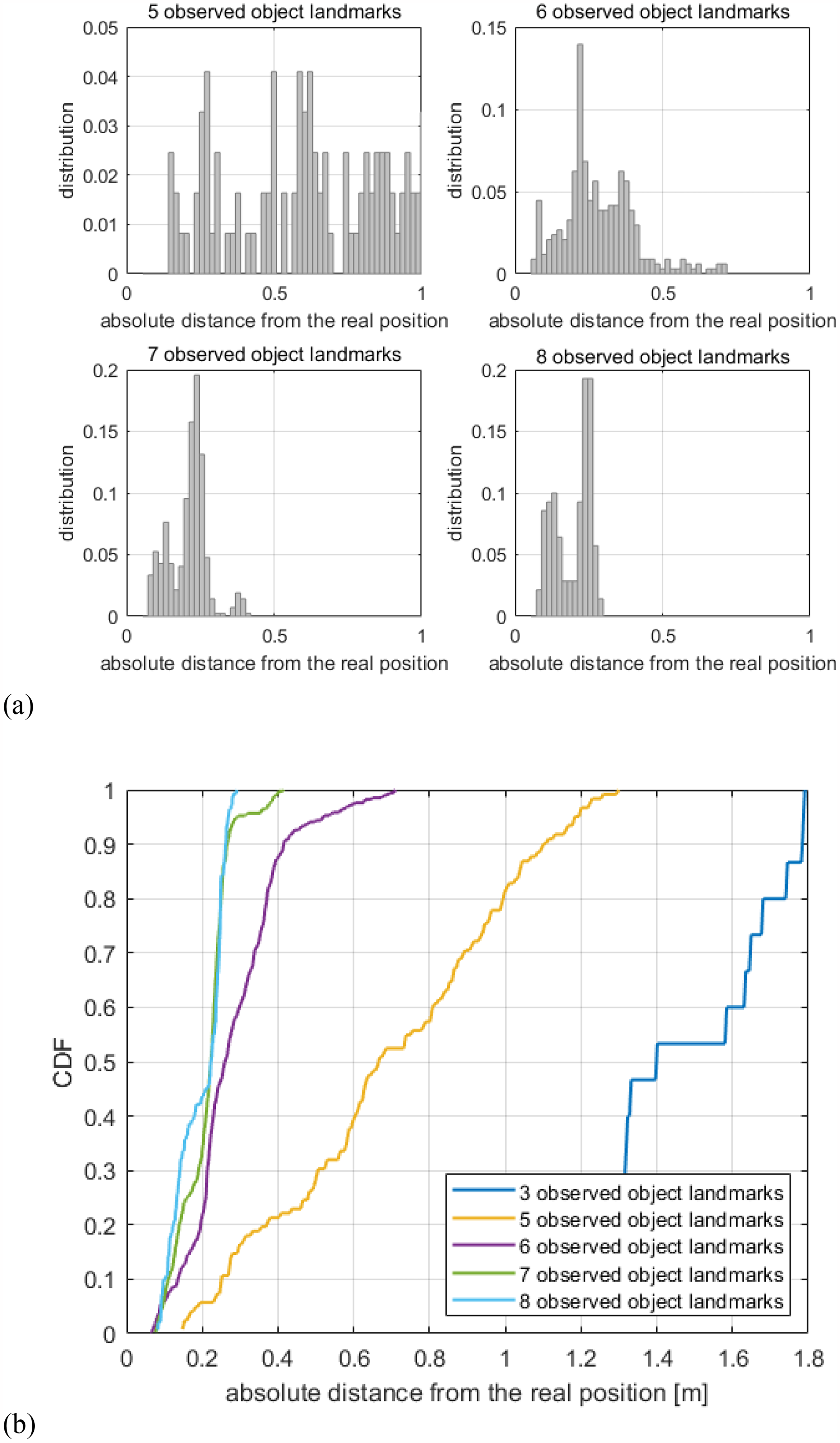
Impact of the number of observed object landmarks on the estimation accuracy. (a) Distribution of the absolute distance between the estimated position and the ground truth position for the cases where the number of detected objects is five, six, seven, and eight, respectively, and (b) CDF of the absolute distance between the estimated position and the ground truth position for the cases where the number of detected objects is three, five, six, seven, and eight, respectively, when the gap between the mapping and the relocalization paths is 2.4 m.
In the second experiment, the mapping and relocalization trajectories are similar, while the illumination changes drastically as seen in Figure 12. Even in this low-light scenario, the visual map holding semantic and geometric information about the objects is established successfully. A comparison between the object feature-based and the point feature-based versions of the proposed visual-assisted relocalization add-on is depicted in Figure 13. By exploiting the semantic information instead of only focusing on the appearance, the object feature-based version of the scheme proves to be less sensitive to the change in lighting conditions. As a benchmark, we also show how it performs when the lighting for relocalization is similar to that for mapping. Although illumination changes result in performance degradation, incorporating objects still boost the robustness of the proposed visual-assisted relocalization add-on.

Illustration of object reconstruction in different illumination conditions. (a) Object reconstruction in a bright lighting condition and (b) object reconstruction in a dark lighting condition.

Comparison between the point feature-based version and the object feature-based in terms of the cumulative distribution function (CDF) of the absolute distance between the estimated position and the ground truth position as the lighting condition of the relocalization session differs from that of the mapping session.
It should be noted that the second experiment took place in a different indoor scene from that of the first experiment (cf. Figures 2 and 12), while the objects transformed into landmarks in the first experiment were set up in the second and treated as landmarks again. The object detection model trained previously is reused as well. The fact that the relocalization performance in both scenarios is promising validates the flexibility of the proposed visual-assisted relocalization scheme.
Autonomous mapping
The results shown in Cheng et al. 23 already indicate that open-area scenarios pose challenges in the mapping session. This subsection focuses on the performance assessment of the proposed autonomous mapping strategy that deals with this issue and further enhances the flexibility and robustness of the proposed visual-assisted relocalization scheme. For these experiments, point features are used.
First, we present a typical indoor scenario where the obstacle-free space is open but with an irregular shape. As introduced earlier, the mapping path is planned by specifying key points on the previously established grid-map as shown in Figure 14(a). The resulting relocalization performance measured in the form of the CDF of the absolute distance between the estimated pose and the ground truth pose is presented in Figure 15. Since the robot traveled only one round in the counterclockwise direction following the planned path and the scene also changed after the mapping session, the pose estimation accuracy seems slightly worse compared to that for other indoor scenarios shown in Cheng et al. 23 Therefore, in the second mapping session illustrated in Figure 14(b), we have selected the key points such that the robot travels around the scenario in both counterclockwise and clockwise directions. Note that the planned path deviates slightly from some of the specified key path points due to the inflation layer of the map. As a result, a better coverage of the scene is achieved through the mapping session, leading to an improved relocalization performance as shown in Figure 15. To summarize, this path planning strategy enabling autonomous mapping contributes to satisfactory pose estimation results and is able to customize the mapping path planning to guarantee scene coverage, enhancing the applicability of the proposed relocalization scheme in diverse scenarios. Note that the rotating mechanism introduced in Cheng et al. 23 serves as a helpful supplement to the first mapping round as well, providing that the robot chassis supports a spinning motion.

Path planning of two mapping sessions. (a) Mapping session 1—one round in the counterclockwise direction and (b) mapping session 2—two rounds, counterclockwise and clockwise, respectively.

Cumulative distribution function (CDF) of the absolute distance between the estimated pose and the ground truth pose with visual maps established in two autonomous mapping sessions.
Path planning for an autonomous mapping session based on the complete coverage path planning (CCPP) method.
For the second experiment, the target scenario is a large underground garage. Two mapping sessions have been carried out, one done manually, and the other in an autonomous manner. For the latter, the mapping trajectory has been planned based on the CCPP method described in the previous section on a 2D grid-map for robot navigation and presented in Figure 16. Figure 17(a) shows the mapping and relocalization trajectories of the two mapping sessions, whereas the pose estimation results are presented in Figure 17(b). For a fair comparison, the relocalization trajectory is the same for the two cases where only the mapping paths differ. It can be seen that the proposed visual-assisted relocalization scheme combined with an autonomous mapping session achieves a high success rate in this dark garage scenario and is superior to the case of manual mapping thanks to a more thorough scene coverage with the CCPP method which is not limited by human experiences and decision making.

Mapping and relocalization trajectories, as well as cumulative distribution function (CDF) of the absolute distance between the estimated pose and the ground truth, pose in a large garage scene in the case of manual and autonomous mapping, respectively. (a) Mapping and relocalization trajectories in a large garage scene in the case of manual (top) and autonomous (bottom) mapping, respectively, and (b) CDF of the absolute distance between the estimated pose and the ground truth pose in a large garage scene in the case of manual and autonomous mapping, respectively.
Last but not least, let us look at another typical indoor scenario, a hall in a building. In this scenario, we have conducted an analysis of the parameter for the mapping path planning that determines the scene coverage as shown in Figure 18. The parameter denoted by

Mapping and relocalization trajectories with different parameters for the path planning.

Cumulative distribution function (CDF) of the absolute distance between the estimated pose and the ground truth pose with different parameters for the path planning.
Conclusion
We have developed a visual-assisted relocalization add-on for both indoor and outdoor autonomous robots to transform not only point but also object features in image frames captured by the visual sensor into abundant natural landmarks of the scene serving to assist the primary LiDAR-based relocalization scheme to accurately estimate the robot’s pose. The novelty of our method lies in its flexible integration with existing LiDAR-based SLAM systems and its ability to improve relocalization accuracy by combining visual and LiDAR data. This framework and its engineering extensions have been described in detail. Experimental results show that the proposed scheme achieves a very high success rate of relocalization in a variety of scenarios and also exhibits a great flexibility and robustness. The proposed incremental mapping mechanism, the multi-camera mode, and the autonomous mapping strategy further boost the performance and robustness of this scheme, rendering it a ready-to-use relocalization solution.
For future work, the coupling of point and object features will be investigated. For instance, point features can be taken as the primary feature type. With a smartly designed scoring mechanism, it is then determined whether object features should be used to enhance the pose estimation performance. On the other hand, the pose estimates obtained with point features and object features can be jointly evaluated, leading to a measure of the credibility of these estimates. It helps guarantee a good quality of the pose estimates provided to the primary LiDAR-based SLAM framework, further boosting the efficiency of the whole relocalization procedure. In addition, it is beneficial to exploit visual features not only for relocalization, but also for the loop closure in the mapping session of LiDAR-based SLAM schemes. One example is SLAM in scenarios with repetitive structures, such as server rooms with rows of server cabinets. Incorporating the rich scene features captured by visual sensors helps avoid wrong loop closures detected by 2D LiDAR-based SLAM algorithms purely based on the structure information.
Footnotes
Declaration of conflicting interests
The authors declared no potential conflicts of interest with respect to the research, authorship, and/or publication of this article.
Funding
The authors disclosed receipt of the following financial support for the research, authorship, and/or publication of this article: This research was funded by Key R&D Program of Shandong Province, China, under Grant No. 2023CXPT094, Key R&D Program of Shandong Province, China, under Grant 2024CXGC010213, and the Jinan City and University Cooperation Development Strategy Project under Grant JNSX2023012.
Data availability statement
Data sharing not applicable to this article as no datasets were generated or analyzed during the current study.