
Abstract
Some of the most valuable science targets for future exploration mission located at the extreme terrains of the planetary surfaces are currently inaccessible to the conventional rovers. The tethered mobile robot with one end fixed to the mother robot or an anchor point has the ability to rappel down steep slopes and traverse rocky terrain, and is a reasonable solution to the above missions. Since the model of the tethered mobile robot can be formulated as a cascade of kinematics and dynamics, a novel backstepping motion control approach is proposed in this paper, in which the kinematic and dynamic controllers are designed independently in a recursive way. In the proposed approach, the optimal distribution of the tether tension and the torque to drive the left and right wheels of the tethered robot is obtained based on the minimization of the system power consumption when the robot traveling on the extreme terrains. In addition, a nonlinear disturbance observer is integrated into the dynamic controller to estimate the disturbance from the rugged terrains. Simulations are performed to verify the effectiveness of the proposed algorithm.
Keywords
Introduction
Conventional planetary exploration robots with six-wheeled rocker-bogie structures, such as Sojourner, Spirit, Opportunity, and Curiosity, are designed to operate on relatively flat terrain with slopes less than 30 degrees. Although this type of robots can travel on about 60% of the Martian surface, 1 some of the most valuable scientific targets lie in the areas with extreme terrain topographies,2,3 which are currently inaccessible to these conventional rovers, such as seasonal dark streaks found on the slopes of Newton's crater of Mars. 1 The traction forces of the rovers may be too weak to support the rovers to traverse a steep slope. In addition, the traditional rocker-bogie suspension structure can significantly increase the possibility of wheel slippage when traversing rough terrains, and even the robot may tumble down on rugged terrains.
In order to explore these extreme terrains, various forms of rovers have been developed. Tethered mobile robot is one type of the rovers designed for steep slopes, gullies and other terrains, 1 which provides tension or support through a tether with one end fixed to the mother robot or an anchor point. The robot can pass through, access or in-situ conduct resource exploration on the extreme terrain areas inaccessible to the conventional wheeled robots. The tethered robots can be further categorized into the tethered legged robots (such as Dante II4,5), the tethered wheeled robots (such as Cliffbot, 6 TRESSA, 7 Axel,8,9 and vScout10–12), among others.
When the tethered robot moves autonomously along the planning trajectory, the unfolding and retracting of the tether must be in accordance with the motion of the robot to maintain the tether taut. Although a variety of advanced control strategies based on backstepping methods,13–15 sliding mode control,16,17 intelligent control 18 and their combinations, have been developed to motion control of the conventional wheeled mobile robots in the complex terrain environments, the conventional trajectory tracking control algorithms are unsuitable for the tethered robots, 1 due to the lack of the tether management operations.
On the other hand, although various control algorithms have been proposed for the tethered robots in the space and underwater environments,19,20 these methods are not applicable for the robots that move on steep terrain with support from a consistently taut tether. In addition, although various tethered robot systems have been developed,21–24 none of them has explicitly proposed robust control strategies to regulate tether tension. Using Visual Teach & Repeat (VT&R) method 25 and Multi-experience VT&R, 26 McGarey et al. 27 proposed a path tracker based on the kinematic model of the robot, where the controller is used to maintain the tether tension when moving on a slope. Polzin et al. 28 proposed a novel optimal tether controller to minimize the risk of tipping while moving on extreme terrains. However, the interaction between the tether tension and the two-wheeled drive torques for the robot in extreme terrain is not taken into account in the proposed approaches above. In addition, the external disturbances and other conditions that may occur in extreme terrain are not taken into consideration.
In light of the coupling effects between tether tension and dual-wheel drive torque, as well as the impact of external disturbances, this paper proposes a novel approach for tethered robots. This approach enables the robot to follow a planned trajectory while keeping the tether taut during movement on steep terrain. The main contributions of this paper are as follows:
A dynamics model of the robot is formulated, in which the coupling effects of the driving torque and the tether tension are considered. The distribution of driving torque and tether tension is comprehensively implemented based on the minimization of the system power consumption. The model of the tethered robot is transformed into the cascade connection of the kinematic and dynamics modules.
29
Therefore, kinematic and dynamic controllers are designed for these two components using the backstepping method. Since the tether tension is prone to external disturbances when the robot is moving on extreme terrain, a nonlinear disturbance observer (NDO) is integrated into the dynamic controller to estimate the slowly time-varying disturbance.
The remainder of this paper is organized as follows. The mechanical system of the tethered mobile robot is introduced and its kinematic and dynamics models are given in Tethered wheeled mobile robot modeling section. The controller is presented for the robot in Controller design section. In Simulation experiments and analyses section, some simulations have been conducted to demonstrate the effectiveness of the proposed method. Finally, the conclusions and analysis are presented in Conclusion section.
Tethered wheeled mobile robot modeling
Mechanical system
The Axel rover is a typical form of a tethered wheel mobile robot,8,9 as shown in Figure 1. The robot consists of two wheels, a connecting frame, a caster arm, a tether, and other components. The two wheels are connected to the connecting frame and driven by two independent actuators. The caster arm in the center of the robot is fixedly attached to the connecting frame with two interfaces. A winch is installed in the center of the frame through the bearing. One end of the tether is fixed to the mother robot or a fixed anchor, and the other end is fixed on the tether winch. The tether is wrapped around the winch before deployment, and its retraction and release are controlled by the rotation of the winch.

Cross-sectional views of the tethered robot.
A tension sensor installed on the robot is used to measure the tether tension, which helps maintain the tether in a sufficiently tight state through feedback control. With the support of the tether, the robot descends to the designated area in extreme terrain for in situ exploration with the retracting and releasing of the tether.
Kinematic and dynamics model
In this paper, a tethered two-wheel differential-drive robot moving on a steep slope, as shown in Figure 2, is considered.

Robot motion scenario diagram.
To facilitate the kinematic analysis, the flat planet surface is generally simplified as a 2D-cartesian plane, meaning the mobile robot moves only in the x and y axes, while the contour and elevation of the z-axis are ignored. 30 To specify the position of the robot, a global reference frame XOY is attached to the ground of the plane, and a local reference frame XrOrYr is attached to the tethered robot, as shown in Figure 3.

Schematic diagram of the tethered two-wheeled differential-drive robot. x and y are the coordinates of the geometric center of the connecting frame, and θ is the orientation of the robot with respect to the x-axis of the global frame.
The position of the tethered robot is described in the global reference frame, by the vector
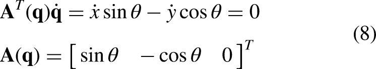
Therefore, the kinematic equation of the mobile robot without slipping can be represented as follows
30
:

For wheeled robots, the Lagrange dynamics approach method is commonly used to establish their dynamics model,
30
which can be represented in matrix form as follows:

Since the castor arm of the tethered two-wheeled robot is designed to be as light as possible in practical applications, therefore its mass and moment of inertia can be ignored which leads to
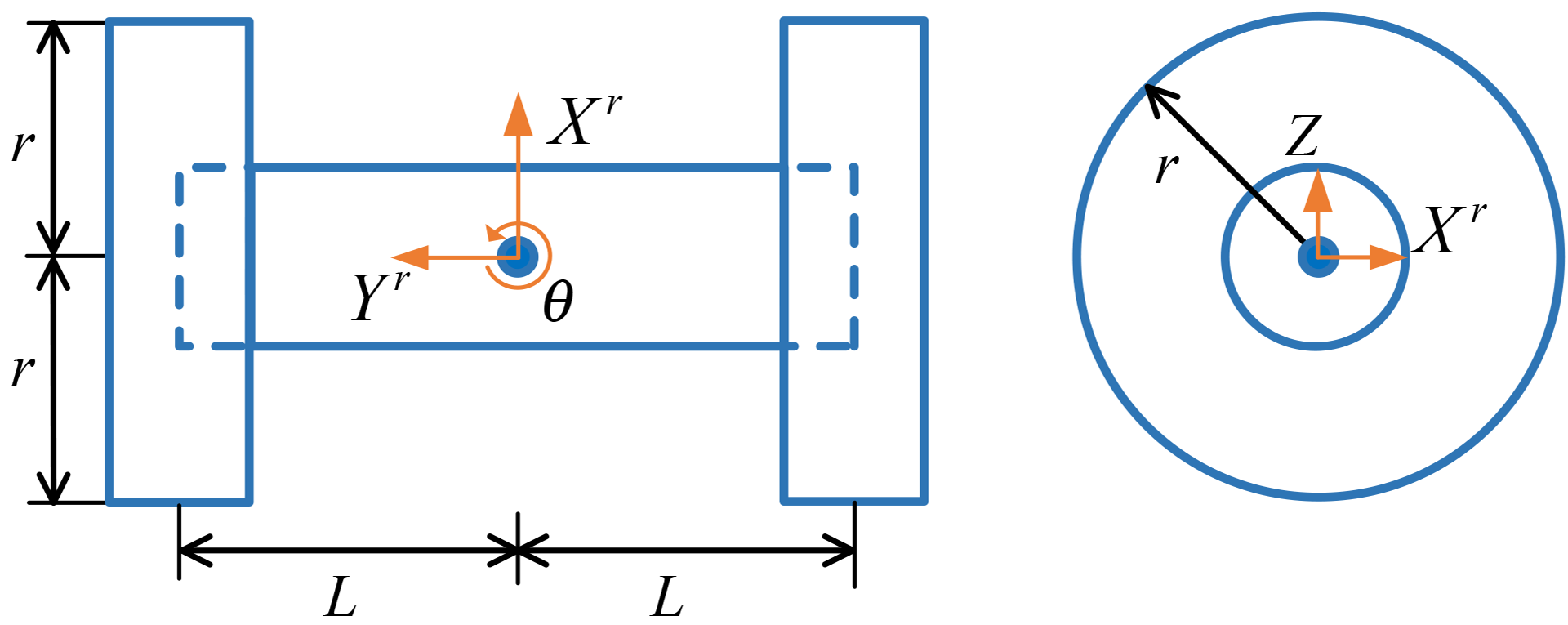
Simplified robot configuration. Xr and Yr are the local coordinates of the vehicle's center of mass (assumed to be at the center of the vehicle). Other variables are defined in Figure 3.
To derive the dynamics model of the tethered two-wheeled robot, assuming that the mass of the connecting frame and the wheels are uniformly distributed and concentrated at the center, the mass matrix

From Figure 2, the inclination angle of the extreme terrain where the robot is located is denoted as


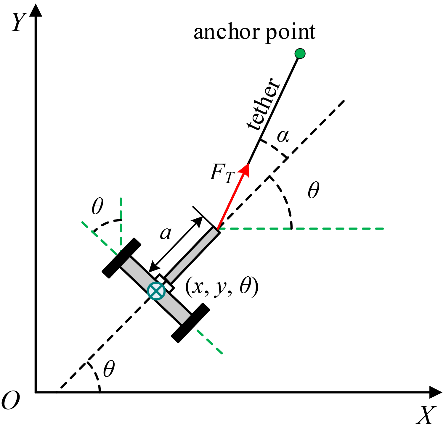
Schematic diagram of forces on a tethered robot. FT is the tension of the tether, a is the length of the caster arm, and α is the angle between the tether and the extension line of the caster arm.
From Figure 5, the input transformation matrix


The generalized driving forces can be further rewritten as follows:


Controller design
The backstepping method constructs a virtual control input corresponding to each order of the state space equations, implementing feedback linearization for each subsystem to achieve closed-loop control. This method is particularly effective for the systematic design of controllers, where each stage incrementally stabilizes the system. It is especially suited to the management of nonlinear systems that exhibit strict-feedback forms. 31 From equations (1) and (9), it can be seen that the robot system can be regarded as a second-order system composed of cascaded kinematics and dynamics models. Therefore, the backstepping method is used to design the controller, developing control laws for each component. 29 In addition, a NDO is integrated into the dynamic controller. Using the system's state variables and dynamics model, the NDO estimates uncertainties from extreme terrain and other factors. The estimated disturbance is then actively compensated in the controller, enhancing the system's stability and tracking performance. The overall architecture of the controller is shown in Figure 6.

The block diagram of control system.
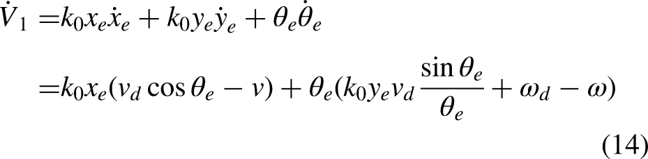
Design of the kinematic controller
Assuming that


Design of the dynamic backstepping controller based on NDO
In order to track the desired velocity
The kinematic and dynamics models derived in Tethered wheeled mobile robot modeling section are as follows:


Design of the NDO
Considering the form of nonlinear observers,
33
based on the system's dynamics equation, the NDO is designed as


Combining equations (19) to (21), the following equation is obtained:


Design of the dynamic controller
The desired velocity control input
For subsystem 2, the Lyapunov function is constructed as


In order to maintain the tether taut during the robot motion, the generalized driving forces acting on the tethered robot are computing from minimization of a power consumption function, which is defined as follows:


Simulation experiments and analyses
Parameters setting
Considering a tethered wheeled mobile robot shown in Figure 1, simulations have been conducted to evaluate the performance of the proposed control approach. The physical parameters of the robot are listed in Table 1.
Physical parameters of the robot.

The control parameters of the kinematic controller are set as follows:
In order to verify the tracking performance of the proposed control approach, a curve reference trajectory is chosen in the simulations. The initial pose of the reference trajectory is
Simulation results
In the simulated environment described above, external disturbances caused by local terrain variations and other factors are represented by two distinct types of signals: square waves, which are used to represent abrupt disturbances in the time interval [40, 55], and low-frequency random noise, which is used to represent gradually varying disturbances in the time interval [60, 100].
The simulation results have been shown in Figures 7‒11. From Figures 7 and 8, the tracking performances of the baseline controller and the controller equipped with an NDO are compared. It can be observed that under no disturbance conditions, both controllers can precisely track the desired trajectory with minor error when the system is stable after 5 s. However, during the 40∼55 s, the emergence of abrupt disturbances led to significant deviations for the baseline controller, with peak errors of about 0.7 meters in position and 0.5 radians in orientation. In contrast, the tracking error of the controller integrated with the NDO can converge to zero, with only slight deviations occurring at the rising and falling edges of the disturbances, with maximum errors reduced to just 0.2 meters and 0.25 radians, respectively.
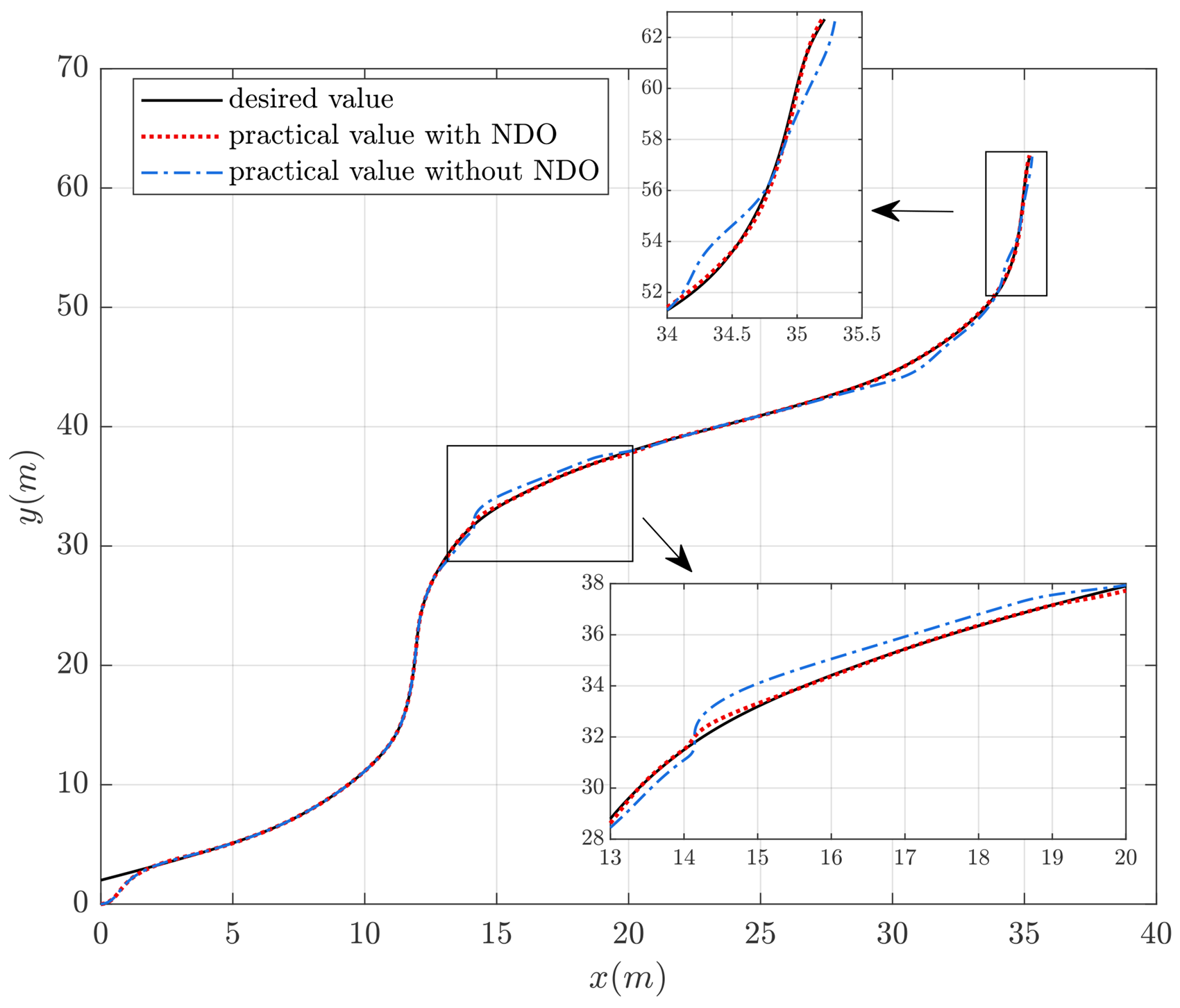
Reference trajectory tracking curve.

Pose tracking error.
Similarly, when the robot encounters slowly varying disturbances from 60 s to the end of the simulation, the results consistently show that significant deviations in tracking the desired trajectory occurred with the baseline controller. And the errors of controller integrated with the NDO reduce to near zero.
Figure 9 shows the simulation results of the estimation of external disturbances. The simulation results demonstrate that the NDO can effectively estimate the disturbances with a response time of approximately 1 s, despite slight overshooting at the rising and falling edges of the abrupt disturbances.

The estimation of external disturbances.
The velocity tracking error of the robot based on two approaches are given in Figure 10. It is shown that the presence of the NDO enables the controller to reduce fluctuations and errors of tracking speed trajectory. This indirectly demonstrates the disturbance estimation capabilities of the NDO.

Speed tracking error.
Figure 11 depicts the variations in input torques and tether tension during the robot's trajectory-tracking process. As the robot begins to encounter external disturbances, adjustments to the dual-wheel torque and tether tension are continually made. Compared to the baseline controller, the controller equipped with the NDO can estimate the disturbances, thereby smoothing the three robot inputs. Furthermore, using the optimal tether tension distribution rules established in this study, the tether tension is consistently maintained below 50 N throughout the entire process. The level of tension is within the safe operating limits for most cables.

The two-wheeled torque and tether tension.
In summary, the above results have shown that the kinematic and the dynamic controller combined with disturbance observer proposed in trajectory, and can also adapt to the local terrain changes and other uncertain factors.
Conclusion
In this paper, a motion control strategy based on the backstepping approach is proposed for the tethered mobile robot. The strategy consists of both kinematic and dynamic controllers. In the dynamic controller, a power consumption minimization approach is proposed to deal with the unique tether tension constraint when the tethered mobile robot moves on extreme terrain, and a NDO is proposed to approximate the irregular disturbances from rugged terrain. Simulation results have shown that the tethered robot has achieved good performance and can move stably along a predefined trajectory using the proposed method.
Furthermore, the power consumption minimization method is used to find a trade-off between the two-wheeled torques and the tether tension. As a result, the power consumption of the robot will be significantly reduced. At the same time, the tension of the tether can be kept within an appropriate range, which reduces the wear of the tether and prolongs its service life.
However, the simplification of the three-dimensional sloped terrain and the robot model in this paper may introduce some potential biases, such as rugged terrain might cause deviations in the robot's position, swinging of the robot's caster arm, and slippage of the dual wheels and so on. Some of these factors have been treated as disturbances in this study, and more detailed research of these aspects is planned for future work.
Footnotes
Declaration of conflicting interests
The authors declared no potential conflicts of interest with respect to the research, authorship, and/or publication of this article.
Funding
The authors disclosed receipt of the following financial support for the research, authorship, and/or publication of this article: This work was supported by the Advance Research Project on Manned Aerospace Technology, Advance Research Project on Civil Aerospace Technology (grant number: 030601, D030103).
Data availability statement
Data sharing not applicable to this article as no datasets were generated or analyzed during the current study.