
Abstract
This paper highlights a welding robot (WR) for its end effector to track a rectangular welding line (RWL). The WR includes five actuators which use a DC motor as a power source. Two controllers are proposed to control the WR's end effector: a main controller and a servo controller. Firstly, based on WR's kinematic equations and its feedback errors using backstepping method the main controller is proposed to design the reference-inputs for the WR's actuators in order that the WR's end effector tracks the RWL. Secondly, based on the dynamic equation of WR's actuator, the servo controller is designed using an active disturbance rejection control method. Finally, a control system incorporated with the main controller and the servo controllers make the WR's end effector robustly track a RWL in the presence of the modeling uncertainty and disturbances during the welding process. In experiment, the main controller which has a function as a master of the control system links to the five servo controllers which have a function as a slave via I2C communication. The effectiveness of the proposed control system is proven through the simulation and experimental results.
Keywords
Nomenclature
Linear velocities of vertical and horizontal sliders, respectively [m/s]
Angular velocities of vertical and horizontal slider's motors, respectively [rad/s]
Rotational angle of torch's direction with respect to y axis and its angular velocities [rad], [rad/s]
Rotational angle and angular velocity of x axis tracking motor [rad], [rad/s]
Angular velocity of the weaving motors [rad/s]
Reference welding velocity [0.007 m/s]
Angle between projection of vr on the plan (y, z) and the z axis [rad]
Angle between projection of vr on the plan (x, z) and the z axis [rad]
General rotational angle of DC motor's rotor [rad]
Modeling uncertainty and unknown disturbance of the actuator.
Introduction
Nowadays, the robotic systems become widely used in welding applications which are harmful and dangerous for the welders. Furthermore, a robotic welding is very practical and useful in the industrial applications in the views of increasing the welding quality, productivity and reducing the welding cost. When the WR's end effector moves along a welding line, its sensors will detect the errors which are defined as the difference between the WR's end effector and the reference point moving with welding velocity along the welding line. The controller system controls the WR's end effector to track the reference point correctly. There are many types of welding robots. For example, Jeon, Park and Kim (2002) proposed a welding mobile robot for Lattice Type of Welding; Bui, Chung, Nguyen and Kim (2003) proposed an Adaptive Tracking Control of Two-Wheeled Welding Mobile Robot with Smooth Curved Welding Path; Santos, Armada and Jimenez (2000) developed a four-legged welding robot for welding a straight and smooth curved welding line which is applied in naval construction process. The problem of these proposed welding systems is that they cannot perform their ability in a rectangular type of welding line.
This paper deals with the WR to weld a RWL which is shown in Figure 1. The WR's end effector is controlled by five mechanism actuators which use a DC motor as a power source. The movement of the WR's end effector can divide into three motions. One is a motion that makes the WR's end effector precisely track a vertical and horizontal welding line. Another changes the welding torch's direction as a value 90° at the corners for the welding torch to be perpendicular to the welding line. For improving the welding quality, the last one regularly and slightly shakes the welding torch for making the WR's end effector weave around a welding line with small amplitude. Moreover, during changing torch's direction at the corners, the welding signal, the first motion and the third motion are interrupted. Furthermore, before practical welding process, two welded base material parts are prewelded. So the opened straight welding line that is not a fillet type is usually distorted. The welding path is discontinuous with two edge corners. In spite of a straight line type in each continuous section, the total shape is a three dimensional one. When the practical welding is processed, the problem for measuring of the welding line is very complicated. To overcome this problem, a type of sensor detecting the tracking errors should be considered. In this paper, a control system for precisely tracking a reference three dimensional RWL even in the presence of the system's modeling uncertainty and the unknown disturbance is proposed. The control system consists of a main controller and a servo controller. The main controller is based on backstepping method and the servo controller is based on active disturbance rejection control method. The effectiveness of the proposed control system which is incorporated with the main and servo controllers is shown by simulation and experimental results.

Rectangular welding line
To obtain a good welding quality, the WR's end effector must precisely and robustly track an un-uniform RWL with the modeling uncertainty and the unknown disturbances. The welding velocity along the welding line must be constant during the welding process and the direction of the welding torch must be perpendicular to the welding line as shown in Figure 1. Moreover, to improve the welding quality, the welding point or the WR's end effector must constantly weaves around a welding line with the amplitude of about 1.5 mm.
The developed WR has five mechanism actuators which use a DC motor as a power source. The system's actuators are a vertical slider, a horizontal slider, a mechanism for x axis tracking motion which is shown in Fig 3, a mechanism of torch holder and a mechanism of weaving torch. Theses actuators above are operated by a vertical slider motor, a horizontal slider motor, a x axis tracking motor, a torch holder motor and a weaving motor, respectively. The function of each actuator is as follows: To weld vertical welding lines, the vertical slider is used to lip up and down the WR's end effector. To weld a horizontal welding line, the horizontal slider is used to shift the WR's end effector horizontally. To move the WR's end effector toward the directions perpendicular to the two sliders for tracking a distorted RWL precisely, the mechanism for x axis tracking motion is used. To keep the direction of the welding torch to be perpendicular to the welding line, the mechanism of the torch holder is used as shown in Figure 2. The mechanism of the torch holder is a torch holder fixed on the axis of the gear box of the torch holder's motor. To improve the welding quality, the mechanism of the weaving torch is used as shown in Figure 3.
It is very difficult to estimate the modeling uncertainty and the unknown disturbance of the whole WR by one controller. To solve this problem, firstly, the system's modeling uncertainty and the system's unknown disturbance are divided into each of the system's actuators. Then the main controller based on backstepping method using WR's kinematic equations is proposed to make the reference-inputs for the actuators in order that the WR's end effector tracks the RWL.

Configuration of the developed welding robot

Mechanism of the torch holder and mechanism of the weaving torch
A condition for the system stabilization is that the outputs of the actuators must track their reference-inputs for the actuators which are given by the main controller. Secondly, to cope with the above condition, the servo controller based on an active disturbance rejection control method is proposed to control the output of the actuator for tracking the reference input which is given by the main controller. Through this method, the servo controller can estimate modeling uncertainty and unknown disturbance of the actuator and then compensate itself. Finally, the control system incorporated with the main and servo controllers is used for controlling the WR's end effector to track the RWL.
Modeling of the WR
To obtain the main controller, the kinematic equation based on the system's actuator of the WR and the tracking errors are considered in the Cartesian coordinate. The coordinate of the WR is shown in Figure 4. The relationship among Figures (2), (3) and (4) is as follows: A coordinate frame's origin O is the reference coordinate frame which is fixed on the right end of the horizontal slider. A coordinates of the frame's origin O1 is fixed on the shaft of the torch's holder motor, so the frame's origin O1 can move along y and z axes through the vertical and horizontal sliders, respectively and rotate around the x1 axis by the torch's holder motor. A coordinate of the frame's origin O3 is fixed on the shaft of the X axis tracking motor. The coordinate frame's origin O3 translates the coordinate frame's origin O1 along x1 and y1 axes as a constant values h and l, respectively. The l value is a length from the origin O3 to the end effector and h is the constant value of projection of an O1O3 on the x1 axis. The E(xE, yE, zE) is the position coordinate of the end effector with respect to the reference coordinate frame.

Coordinate frames of the welding robot
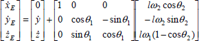
The kinematic equations of the WR's end effector with respect to the reference coordinate frame can be described as follows:

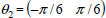
To design a servo controller for each system's actuators which uses a DC motor as a power source can estimate modeling uncertainty and disturbance of the actuator and then compensate itself. The servo controller based on an active disturbance rejection control method is proposed. This method uses extended state observer (ESO) to estimate the modeling uncertainty and the disturbance of the actuator. So the dynamic equation of each system's actuator can be expressed as follows:

Main controller
Based on the system's kinematic equations, a backstepping method using Lyapunov function is proposed to design the main controller. The main controller makes the reference-inputs for system's actuators in order that the tracking errors ei (i = 1, 2, 3) must go to zero as t → ∞. It means that the WR's end effector tracks a reference point which moves on the RWL with a constant velocity as shown in Figure 5. Moreover, the following two assumptions are needed to design the main controller.
Assumption 1
The direction of the welding torch is assumed to be perpendicular to the welding line. The rotational angle of the torch holder's motor is assumed to be changed only at the corners. So while the WR's end effector is tracking a vertical and a horizontal welding lines the values of θ1 are –π/2, 0 and π/2, respectively.
Assumption 2
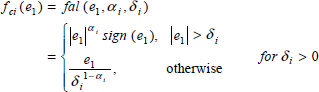
The x axis tracking motor is designed to control the WR's end effector to track the welding line precisely. So the bound of θ2 is assumed to be as follows:
The tracking errors ei (i = 1, 2, 3) are defined as follows:


Reference point and tracking errors
Based on the WR's kinematic equations, the first derivative of the tracking errors is obtained as follows

By the assumption 1,

The Lyapunov function is chosen as follows:

The derivative of V yields

As we know, the velocities of the vertical and horizontal sliders are controlled by angular velocities of DC motor. The relationship between them is as the following:

An obvious way to take the control outputs of the main controller, ω2, ω
y
ω
z
, θ1, ω
w
are chosen as follows

From Eq. (9) and Eq. (11), the following equation is obtained.

Clearly if ki > 0 (i = 1, 2, 3) and Eq. (11) are chosen, V ≥ 0 and V̇ ≤ 0. It means that ei → 0 (i = 1, 2, 3) as t → ∞ by Lasalle's invariance theorem and Lasalle-Yoshizawa theorem (Utkin, Guldner, and Shi, 1999). That is, the system is stable in the sense of the Lyapunov under the conditions of ki > 0 (i = 1, 2, 3) in Eq. (12), assumptions 1 and 2.
As we know, the modeling uncertainty and the disturbance of the WR is divided into sytem's actuators. So the problem is to design a servo controller for system's actuator which can estimate the modeling uncertainty and the disturbance of the actuator and then compensate itself. To overcome this problem, the servo controller based on the active disturbance rejection control (ADRC) method is proposed to control the output of the actuator. The ADRC is used successfully by Huang and Han (2000) and Y. Hou, Z. Gao, F. Jiang, B.T. Boulter (2001). The servo controller consists of an estimated extended state observer (ESO), a profile generator and a nonlinear PD controller as shown in Figure 6.

Block diagram of servo controller
where r(t) is the angular velocity reference input of an actuator's motor which is given by the main controller, u(t) is the controlled current of the actuator's motor, w(t) is the external disturbance, ω(t) is an angular velocity output of the actuator's motor which implies the output of the actuator.
The modeling uncertainty and the disturbances of the actuator are estimated by ESO and compensated during each sampling time simply using only the measured angular velocity output of the actuator's motor. So the servo controller is designed without an explicit mathematical model of the actuator. This is the reason why the simple dynamic model of the actuator in Eq. (3) is used.
The state space form of Eq. (3) can be rewritten as follows:

The ESO is a unique nonlinear observer designed to estimate f() which is augmented as a state for the system as follows:
By the extended state observer for the system, the system (14) is the ESO of the system (13). It has the properties zi(t) → xi(t), i = 1, 2, 3, as t → ∞. The demonstration of ESO convergence is proven by Huang and Han (2000).
From the reference angular velocity input for the servo controller, r(t), and the sampling time of the system, the profile generator generates the signals v1(t) and v2(t). v1(t) is the rotational angle and v2(t) is the angular velocity. The relationship of the output of the profile generator v1, v2 and its input reference r(t) is as follows:

The nonlinear PD controller makes the errors ε1 and ε2 converge to zero

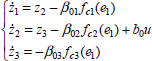
ε1 = v1 – z1 and ε2 = v2 – z2 are the position error and the angular velocity error, respectively. f1() and f2() are appropriate nonlinear functions such as follows:

The output of the total servo controller is proposed as follows:
This section is divided into five parts. Firstly, the experimental sliding actuator for the servo controller is described. Secondly, the experimental WR for the incorporation of the main and servo controllers is described. Thirdly, a scheme for measuring the errors is proposed. Fourthly, to show the effectiveness of the servo controller for an actuator which uses a DC motor as a power source, the servo controller is applied to the sliding actuator as shown in Fig. 7 for tracking the reference input even in the presence of the modeling uncertainty and the unknown disturbance of the sliding actuator. The effectiveness is proven through the simulation and experimental results. Finally, the effectiveness of the incorporation of the main and servo controllers which are used to control the WR's end effector is proven through the simulation and the experimental results.
Experimental sliding actuator for the servo controller
The dynamic model in Eq. (3) is applied to the actuator which uses a DC motor as a power source as shown in Fig. 7. In this experiment, an external disturbance is made by putting up or putting off the weight on the slider's table of the actuator. The actuator's reference input r(t) is a step function which has a period of seven seconds. The angular velocity ω(t), the output of the actuator's motor is measured by the optical encoder. The microprocessor PIC16F877 and a DC motor driver TMD 18200 are used in the control board.
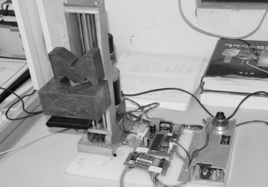
Experimental sliding actuator for the servo controller
The experimental WR includes five actuators as shown in Fig. 8. The main controller is used to control the movement of five actuators for WR's end effector tracking a RWL. The servo controller is applied to each of system's actuators. Each of the outputs of the actuators is performed by each of the servo controllers for tracking their reference-inputs which are given by the main controller. The scheme control system is shown in Figure 9.

Experimental welding robot for welding a RWL

Block diagram incorporated with the main and servo controllers
The control system of the WR is based on the integration of six microprocessors using PIC16F877. One is used for the main controller which has a function as a master of the control system. The others are used for the five servo controllers which have a function as slaves of the control system. The master communicates to the slaves via I2C communication.
The control system of the WR includes three modules of two PIC16F877's boards as shown in Fig. 10.

the module of 2 PIC16F877 board
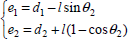
In this section, a simple scheme for measuring the tracking errors e1, e2 is shown in Figure 11. The value of e1, e2 is obtained by using potentiometer. Two linear potentiometers with a ball at its end are fixed on the torch holder to measure the distances d1, d2. The relationships between e1, e2 and d1, d2 is as follows

In experiment, it is very difficult to design a sensor for measuring the initial error of e3 because the error e3 is produced along the welding line. So the initial error of e3 is setup to be equal to zero at the beginning by the mechanism of the stopper. During the welding process, the error e3 is observed by using information obtained from two encoders of slider's motors and the angles φ and γ in Eq. (21).
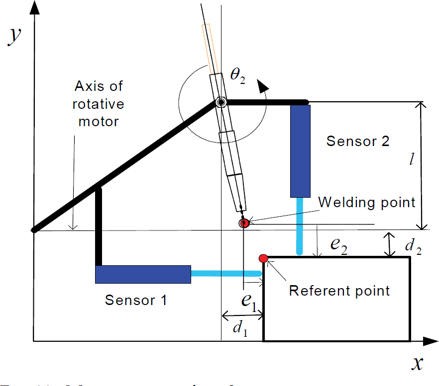
Measurement of tracking errors
Experimental results
The servo controller is applied to the sliding actuator. The simple dynamic model of an actuator without an explicit mathematical model in Eq. (3) is used. The dynamic model of the sliding actuator in Photo 7 is as the following:

Parameters used for the servo controller

The experimental results are shown in Figures (12) and (13). The experimental results show that the output of the actuator tracks its reference input very well and robustly even if a big unknown external disturbance occurs at four second after start.
For simulation, firstly, a general dynamic model of an actuator which uses a DC motor as a power source is used to describe the dynamic model of the sliding actuator as shown in Photo 7. Secondly, this dynamic model is rewritten into the simple dynamic model form of Eq. (22). Finally, to compare the simulation results with the experimental results, the Matlab is used. The general, real dynamic model is as follows:

The dynamics of DC motor in Eq. (23) is rewritten into the form of Eq. (22) with b0 as follows:

The simulation results based on known modeling uncertainty and known disturbance of the actuator are compared with the experimental results in the same sliding actuator and conditions. The parameters of the sliding actuator are shown in Table 2.
Parameters of the sliding actuator

with b0 = 80 chosen in experiment, a = B/J = 1.1235 and b = k/J = 74, from Eq. 24, the function 
Figures 12 and 13 show that the output of the experimental results for rotational angle and angular velocity of DC motor is bounded around the simulation results. Furthermore, the outputs track the reference input very well. Figure 14 shows the efficiency of ESO which is used to estimate the modeling uncertainty and unknown disturbance. State x3 and its estimation z3 = f() is very sensitive with internal and external disturbances. However, z3 converges to x3 just after fluctuating. Figure 15 shows that the current control input is very fast adapted to actuator's disturbances. Finally, the simulation and experimental results show that the servo controller is very powerful and useful for the actuator which uses a DC motor as a power source by using the simple dynamics in Eq. (3).

Simulation and experimental results of rotational angles of the actuator's motor

Simulation and experimental results of angular velocities of the actuator's DC motor

Simulation result of extended state x3 and z3.
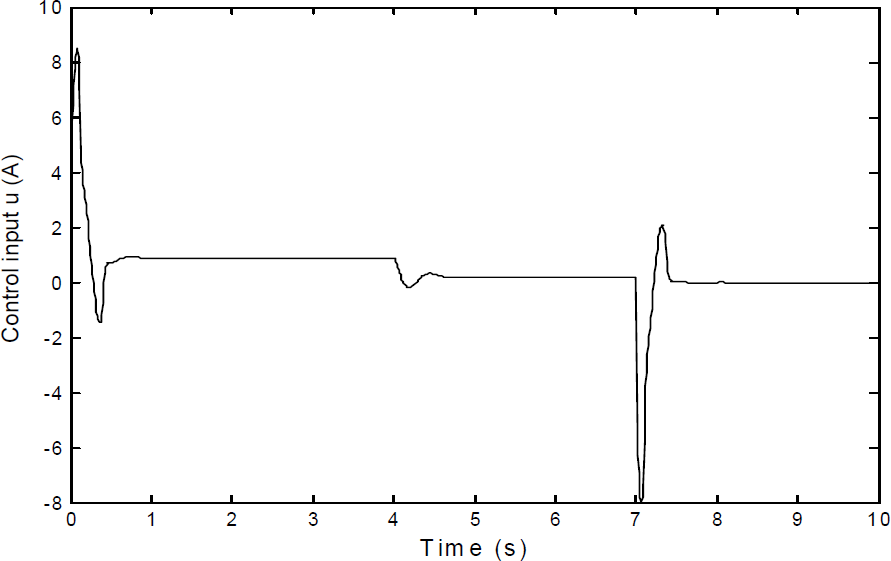
simulation result of current control input u for the actuator's DC motor
The simulation has been done with the constant welding velocity vr = 7.5 × 10⁻³ m/s and the parameters of the main controller are chosen as follows k1 = 25; k2 = 4 and k3 = 1.7. In Figure 16, the trajectory of WR's end effector tracking the RWL with the initial values of errors e1 = 5mm, e2 = −5mm and e3 = 5mm is shown. In Figure 17, the simulation results of tracking errors of e1, e2, e3 at beginning is shown. All the tracking errors converge to zero after three seconds. So it is shown that this result can apply to welding process.

Results of trajectories of the end effector and its reference

Results of the tracking errors at the beginning
The experimental results of the tracking errors are shown in Figure 18. The experimental results are bounded around the simulation results and stable around zero value. It means that the proposed control system which is incorporated with the main controller and the servo controller has good tracking performance to the welding line. Figure 19 shows the whole movement process of vertical slider and horizontal slider and the rotational angle of the torch's holder.

Tracking errors at the beginning

Linear velocities of sliders and rotational angle of the torch holder motor
In this paper, a robot for welding a RWL is developed. A control system incorporated with the main and servo controllers is proposed to control the WR's end effector for tracking a RWL. The main controller is designed based on backstepping control method using Lyapunov function. The servo controller is designed based on active disturbance rejection control method. The incorporation of two controllers makes the WR's end effector track RWL robustly. The system is stable in the sense of Lyapunov. The simulation and experimental results show that proposed control system has good performance.