
Abstract
Split-type flying car will play an important role in the future transportation. This paper adopts a guidance method that couples visual information and depth information, and improves the docking accuracy through the mutual cooperation of the drone and the vehicle. Firstly, a multilevel docking marker is designed to achieve adaptive target matching within different distances during the docking process. The marker has strong robustness and can adapt to complex scenes such as occlusion, strong light, and large angle tilting, providing the redundant corner points required for machine vision detection pose information accurately. Secondly, a three-dimensional pose estimation algorithm is proposed, which can introduce depth information to correct the homography matrix. The algorithm combines the advantages of strong robustness to multilevel marker detection and high accuracy of depth information, and can output millimeter-level precision pose information in different environments, different inclination angles, and different occlusions. Finally, a flying car model experiment was carried out, and the results showed that the guidance technology can obtain millimeter-level precise pose information during the entire process of long distance-near distance-completion of docking, thus realizing precise docking.
Highlights
A multilevel marker was designed to provide suitable recognition objects for UAVs at different stages of docking.
A method combining machine vision with depth camera was proposed, and the fusion of visual and depth information significantly improved the recognition accuracy.
By adopting the dual AprilTag code design, the center coordinates of the marker were stably output during recognition, which solved the problem of reduced recognition accuracy in some UAVs due to their own shaking.
The application of docking guidance technology to split-type flying cars provided a solution to a key aspect in the development of the field.
Introduction
In recent years, the advantages of split-type flying cars have gradually become prominent, in parallel with the development of UAVs (unmanned aerial vehicles). 1 These flying cars possess the capability of vertical takeoff and airborne task execution akin to drones, as well as functionalities of road-based vehicles and control centers. As such, they have the potential to elevate the two-dimensional traffic network into three-dimensional space, autonomously perform precise positioning, and seamlessly integrate with other devices such as ground stations, ships, and aircraft, without the need for human intervention. It is expected that they will play an important role in modular transportation, commercial delivery, and emergency rescue, 2 ultimately transforming the current traffic.
In various docking or positioning problems, appropriate identification markers can enhance optical, infrared, or other features to improve success rates. Identification markers can be divided into two categories: natural markers inherent to the target platform itself3,4 and artificial markers. Artificial markers can be designed according to the working environment and applicable scenarios, with higher discrimination and robustness, and are extensively employed in various docking or positioning scenarios.
Jie et al. 5 and Li et al. 6 proposed different algorithms based on a rectangular color identification marker to achieve position calibration for robots. The experimental results showed an error of 1.5° and 3 cm, meeting the requirements for conventional positioning accuracy. Shao et al. 7 and Miguel et al. 8 used identification markers with clear feature points to guide UAVs to quickly capture landing platforms, thereby significantly reducing the amount of image processing required by onboard computers. Zhao et al. 9 designed a ground identification marker to improve position recognition accuracy while UAVs are moving and experiencing image shaking. Liu et al. 10 designed a ground cooperative marker that can be recognized at different heights, which validated the proposed ground identification marker's ability to improve UAVs landing accuracy in the Gazebo simulation environment. Among many artificial markers, the Apriltag code proposed by Olson et al.11,12 at Michigan State University in 2011 is widely used in the fields of robot positioning and docking.13,14 As a visual benchmark system, it has been widely recognized by scholars for its good tolerance and high accuracy in rotation, lighting, jitter, slight occlusion, and blur.
For the docking problem of split flying cars, many scholars have proposed different solutions.15–18 Commonly used methods include the combination of high-precision global positioning system (GPS), inertial sensors, and air pressure sensors, or the guidance systems carried by UAVs such as motion capture systems, infrared lasers, and machine vision. However, GPS signals are susceptible to interference in forests, deserts and other environments, resulting in a sharp drop in accuracy. Motion capture systems are generally used indoors. Machine vision positioning technology has the characteristics of low hardware cost and rich information. At the same time, vision sensors have the advantages of portability, low power consumption, low cost, and easy coupling with other information. By analyzing the images captured by the camera, UAVs can determine their position and direction relative to the target object, thereby achieving accurate positioning. Machine vision positioning plays a crucial role in the autonomous flight and docking process, improving their positioning accuracy and safety. Cheng et al. 19 proposed a method that combines ultra-wideband and visual positioning, and successfully guided UAVs to land in the target area without GPS. Ma et al. 20 proposed a ground stereo vision guidance method that simulates human vision when studying UAV landing without GPS. They verified that this method has better guidance effect than GPS, and the framework is simple, but the disadvantage is that the guidance accuracy significantly depends on the image threshold parameter. Gangik et al. 21 combined the speed data of the moving platform with the information obtained by the UAV's vision to achieve stability when landing on a moving platform. Progress has also been made in the application of neural networks to image positioning technology. For example, Zhu et al. 22 used a neural network algorithm for image processing, which reduce redundant information and solve the problem of target occlusion through image feature point matching, and achieve a positioning accuracy of 0.1 m in experiments. Ding et al. 23 proposed a new target detection network that changed the candidate filtering rules and refined the feature map. The detection accuracy of UAV image targets can reach 89%, and the positioning error is within 0.3 m.
After arriving at the target location, UAVs need to accurately determine their attitude angles to establish a connection or fixation with the target object. Attitude angles, which typically include the roll, pitch, and yaw angles of the UAV, can be used to determine its position and direction. Machine vision technology can be used to analyze images captured by the UAV's camera to determine its current attitude angle. Although detection technology for attitude angles has been developed for ground robots with fewer degrees of freedom, there is limited research on attitude detection technology for UAVs. Mae et al. 24 proposed a three-dimensional attitude detection method based on local feature matching of the target, which requires the robot to obtain some reference information in advance and has poor versatility. Asadi et al. 25 and Li et al. 26 estimated the UAV's attitude by fusing the images captured by the camera with other information; however, this increased the processing load on the onboard computer. Aslan et al. 27 and Madhuanand et al. 28 combined visual information with artificial intelligence, using neural networks to estimate the UAV's attitude after extensive learning, however, this requires a large database to support it in the early stages. Zhou et al. 29 proposed a wing-linking technology for lateral docking of UAVs when studying the linkage of fixed-wing UAV groups, forming a high aspect ratio fixed-wing. Nadir et al. 30 designed an UAV capture device that provides a certain tolerance for the docking attitude angle of UAVs.
In summary, existing research on UAVs positioning and docking mainly relies on 2D information positioning or GPS positioning, and there is still room for further improvement in terms of efficiency and accuracy. To overcome the problem of GPS system interference in complex environments and poor stability and limited field of view of pure visual guidance, this paper proposes a high-precision positioning method based on the fusion of Apriltag and depth camera, 31 and designs a multilevel identification marker. The homography matrix of the identification object is obtained through an algorithm to estimate the attitude angle of the drone. To solve the problem of visual image blurring caused by drone vibration, this paper applies a more stable structured light and visual fusion ranging method, which improves the docking accuracy of the drone to the millimeter level.
Docking method
Multilevel identification marker
During the docking process between the drone and the ground vehicle, to ensure good visual accuracy at different distance ranges, this paper designs a multilevel identification marker as shown in Figure 1. The identification marker includes an outer frame, an H-shape, and two Apriltag codes, which serve as visual recognition objects for different stages. The outer frame can be quickly located and listed as a candidate docking area when the drone searches for the target at a long distance. When performing pixel clustering calculations, the convex quadrilateral shape of the outer frame can be more efficiently recognized. After the outer frame is recognized, all detected convex quadrilaterals are screened. The obvious corner features and symmetrical structure of the H-shape can provide distinct morphological features for the screening process, ensuring the accuracy of the screening process. The pixel coordinates of each corner point are used to preliminarily calculate the center position of the identification object, providing suitable directional guidance for the drone. After the drone descends to the specified height based on the previously obtained position information, the double-code recognition of Apriltag is activated. The eight corner points can provide stable position information for estimating spatial position and 3D attitude, thereby achieving precise end-point docking. As the drone gradually approaches the vehicle, the identification marker provides 2D and 3D information in a hierarchical manner, helping the drone to continuously adjust its position and attitude.
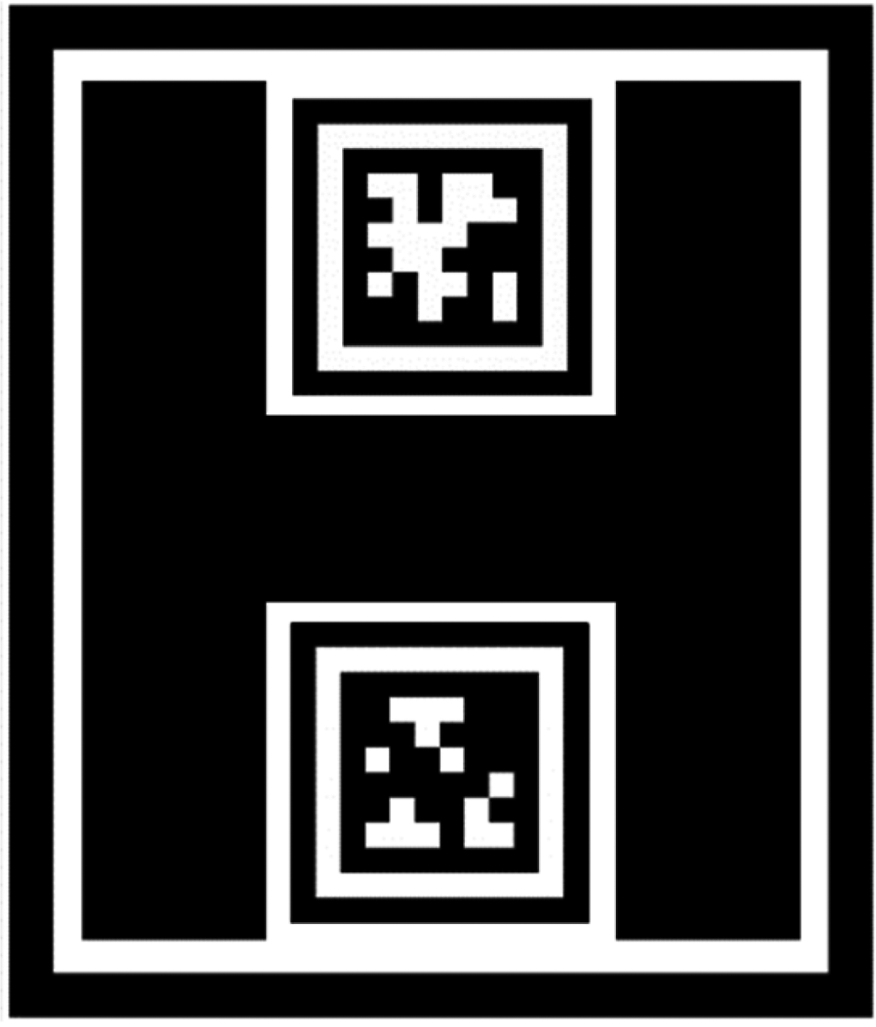
Multilevel identification marker.
Docking process
The drone uses GPS and inertial navigation systems to move to the landing point. In the GPS guidance process, once the marker appears in the camera's view, the visual guidance system is activated. Thereafter, the flight control system increases the weight of the pose information feedback from the visual guidance system, and decreases the weight of the GPS feedback simultaneously. When guiding the drone to a vertical height of about 3 m and a horizontal distance of about 0 m, further increase the weight of visual information. Further positioning is performed based on the acquired location information. Adaptive thresholding, continuous boundary segmentation, quadrilateral fitting, homography transformation, and matching with the Apriltag library are performed on the H contour and the inner double Apriltag, and the position and direction information of the target point is finally determined. Then, the drone is guided to a height of 1 ± 0.02 m and a horizontal distance of 0 ± 0.02 m. After entering the final localization, the depth camera is turned on, and the depth information is introduced. After configuring the depth stream and the color stream, the depth frame and the color frame are aligned, and the depth information is fused to improve the accuracy to the millimeter level and perform precise landing. The docking process is shown in Figure 2. During the docking process, the visual guidance system needs to identify different targets at appropriate stages, as shown in Figure 3.

Schematic diagram of the docking process.

The operation logic of the guidance system.
Position and attitude detection
The entire docking process can be divided into three stages: in the first stage, the rectangular outline is identified, and the center point position is roughly calculated; in the second stage, the Apriltag identification is recognized and the position and attitude angle of the identification are accurately calculated; in the third stage, the depth camera is activated for high-precision guidance and descent of the end point.
Marker outline hierarchy
Firstly, the input image undergoes preprocessing to obtain a binary image. Subsequently, the target marker is identified by filtering the contours based on the predetermined contour relationship, which is in the form of an “H.” Figure 4 illustrates the recognition logic flowchart. The binary image comprises only two colors, black and white (where 0 and 1 correspond to the respective colors). The Suzuki contour tracing algorithm 32 is employed to search for contours, following a series of steps: firstly, the starting point of the contour tracking is determined, which is generally the pixel with the highest leftmost position on the contour. Secondly, different sequences of boundaries are marked according to the corresponding tracking rules, and the outer boundaries or holes are determined based on the sequence numbers. All contours are searched and the contour relationship tree is ultimately established.

The recognition logic of the “H” pattern.
The intersection point of the two straight line boundaries is the inflection point. After obtaining the boundary, it can be determined whether it is the target “H” by counting the number and relative position of the inflection points.
By judging whether the boundary relationship of “border-H-letter-double code” satisfies the hierarchical relationship function of the number of corner points, that is, formula (1) (Figure 5):


Corner point diagram.
The “H” graph that satisfies the relationship tree can be considered as the target marker, and the misjudgment rate can be greatly reduced through this screening, and the recognition rate can reach 100% in the experiment. The recognition situation of “H” in complex environment is shown in Figure 6.
Recognition of the letter “H” in a complex environment.
Dual-Apriltag code position and attitude calculation
Dual-Apriltag code recognition
After recognizing the letter “H,” the second stage of precise docking is initiated, which involves the important tasks of rapidly identifying the docking point and processing the pose information. At this stage, RealSense opens the RGB color camera to recognize the Apriltag identification, and transmits the calculated position and orientation to the flight control system for attitude adjustment, preparing for the final third stage docking.
When processing dual-Apriltag markers, the center coordinates of the entire marker are calculated based on the information of the four corner points of each marker. Then, the instantaneous angular deviation between the drone and the marker code is calculated based on the center point coordinates of the two markers. The error is controlled within 0.2° to meet the docking accuracy requirements. Line segment detection is performed on the filtered and grayscale processed image. The gradient intensity of each pixel is calculated, and clustering is performed based on gradient intensity and direction. Multiple adjacent pixels are considered as a single edge.
After completing line segment detection, grouping is performed. If the distance between the endpoint of the previous edge and the starting point of the next edge is less than a certain threshold, the two lines are connected counterclockwise. After all line segments are grouped, filtering is performed to remove groups that do not meet the conditions, leaving the remaining groups to form a quadrilateral. Then, the quadrilateral is encoded based on the point lattice inside it to determine the encoding method. A threshold model is established by extracting the average pixel values of the outermost and second outermost point lattices, resulting in a spatial variation model based on the pixel intensity of the outermost and second outermost perimeters:


Apriltag code identification process.
Horizontal position calculation
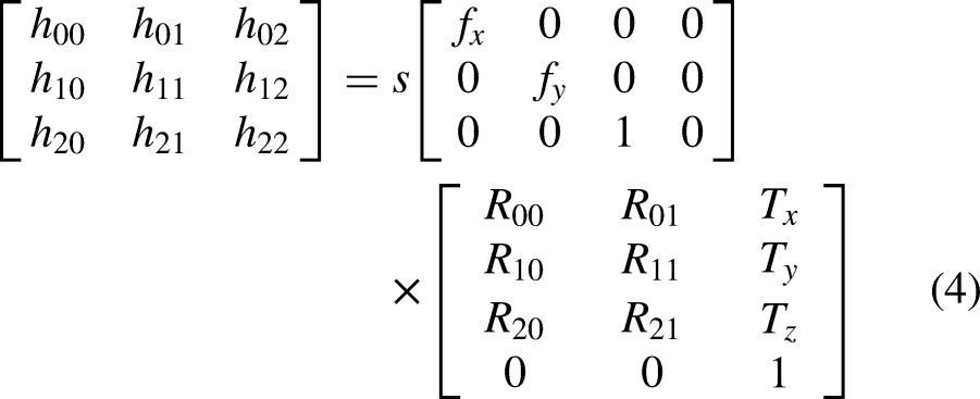
In order to calculate the relative pose between drones and objects accurately, it is necessary to transform the two-dimensional image coordinates into three-dimensional spatial coordinates. This requires the transformation of the image coordinate system to the world coordinate system using the homography matrix. The homography matrix is given by:

Docking of detachable flying cars requires even higher accuracy than fixed-point landing, with the horizontal angle during docking needing to be controlled within a certain range. The double Apriltag code docking system proposed in this paper can effectively solve this problem. After obtaining the image coordinates of the two Apriltag codes, the center line between them is selected, and the midpoint on the line is taken as the center of the entire target area. Docking work is carried out based on this point as the docking center.
Compared to the four corner points of a single Apriltag marker, the double marker proposed in this paper provides eight corner points for estimating relative position. Each corner point may have a certain recognition error when detected by the visual system, resulting in a deviation of several pixels between the detected value and the true value. Assuming that the error values for each pixel detected by the system follow a standard normal distribution, the position information estimated based on more corner points is more stable. This, to some extent, solves the issue of inaccurate recognition caused by drone shaking.
Figure 8 demonstrates the stability comparison between double and single markers. The black line denotes the midpoint of the double marker connection line, while the red line represents the center point of a single marker. During drone shaking, especially during horizontal rotation, using the midpoint of the double marker connection line as the center of the marker can significantly improve stability.

Comparison of stability between dual-code and single-code systems.
During the docking process, the horizontal angle control is divided into two parts, namely the azimuth angle ∠1 between the target point and the drone, and the angle ∠2 between the target point and the drone in the horizontal direction. The Apriltag code with ID “1” is considered as the “head” of the drone docking, while the code with ID “2” is considered as the “tail.” The center coordinates of the “head” are denoted as


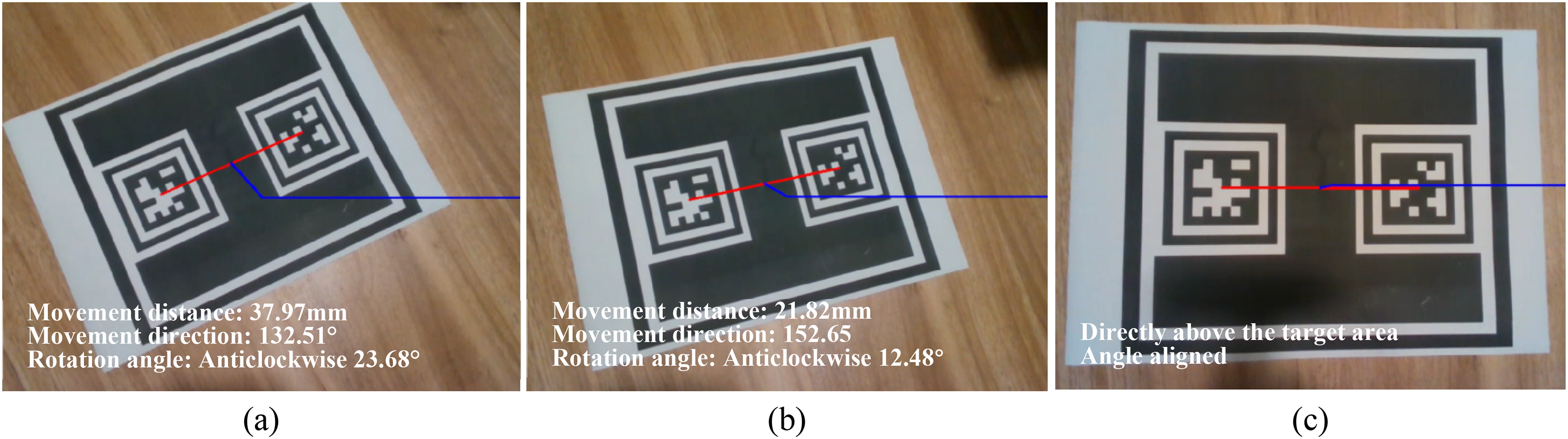
Angle and distance recognition.
3D attitude angle calculation
In order to determine the three-dimensional pose of the marker, it is necessary to rotate, scale, and translate the marker in the world coordinate system to match its position in the camera coordinate system. The rotation and scaling can be represented by matrices, while translation is represented by coordinate addition. To enable matrix multiplication, homogeneous coordinates are introduced, elevating the camera coordinate system from 2D to 3D coordinates.
To obtain the three-dimensional coordinates of the target point in the color coordinate system, which is an ordinary monocular vision system, four coordinate system transformations are required: the world coordinate system, camera coordinate system, image coordinate system, and pixel coordinate system (as shown in Figure 10).

Imaging model.
From the perspective of the model relationship, the relationship between the pixel coordinate system


After detecting the Apriltag code, the visual system generates its homography matrix. Based on the conversion between the rotation matrix and Euler angles, the Z-axis Euler angle can be selected as the angle between the Apriltag code and the camera. Then, the normal vector of the plane where the code is located and the angle between the camera can be calculated, and the three-dimensional pose angle information can be obtained.
High-precision docking with fused depth information
Monocular visual ranging 34 and binocular visual ranging 35 are two commonly used methods f to obtain depth information using vision systems. However, in the actual docking scene, the UAV will approach the vehicle body from various angles, and the accuracy of such methods is difficult to guarantee. Moreover, in the process of docking, the image is easily affected by illumination, tilt angle, mechanical structure, and so on, and it is difficult to complete high-precision docking only relying on visual guidance. Therefore, more accurate and reliable information other than vision is needed to couple with it. The commonly used technologies include infrared laser, structured light, and so on. Structured light technology is a kind of active ranging method. 36 It is relatively lighter, easier to install on the cabin of a flying car, and consumes less power than laser. Unlike visual ranging, this technology encodes or characterizes the projected light source to obtain the depth modulation of the object surface. The structured light source has many feature points or codes, thus providing many matching corner points, which can be conveniently used for feature point matching. In addition, depth cameras have higher accuracy, faster calculation speed, and are not limited by the field of view. In this study, the RealSense D435i depth camera was used for ranging, and the ranging principle diagram is shown in Figure 11.

Structured light 3D visual perspective model.
Based on the images captured by the left and right infrared cameras, depth is calculated using the triangulation method. On the basis of binocular visual ranging, a fixed infrared dot matrix texture pattern is projected by the middle infrared projector to enhance the texture information of the measured surface. When the left and right infrared cameras detect different dot matrix patterns, the patterns are sent to the built-in depth processor, and the depth of each pixel point is calculated based on the binocular ranging principle. Compared with the ordinary binocular ranging method, this camera uses the emitted infrared dot matrix to enhance the feature information of the measured object, achieving the goal of improving the accuracy of depth information.
The previous discussion focused on how to obtain the homography matrix by visual recognition of the identifier, and then estimate the relative coordinate information between the UAV and the docking platform, including height, horizontal distance, horizontal angle, relative tilt angle, and other parameters, which are all based on the same H matrix. In addition to obtaining depth information through visual measurement, it can also be obtained using a depth camera carried by the UAV. The accuracy of the two methods at different distances has been compared in the previous text. Therefore, in the distance interval where the depth camera has higher accuracy, the height information obtained by the depth camera can be used to replace the height information obtained by visual measurement, and then H can be corrected to obtain a more accurate depth homography matrix

Experiment
System composition
The visual guidance system is comprised of three main components: information acquisition, algorithm processing, and information communication. The hardware system includes a SMART-250 UAV, an Intel RealSense D435i depth camera, an on-board computer (NVIDIA Jetson TX2), and a ground docking identifier. The RGB lens in the depth camera is used to obtain visual information, and the infrared lens is used to obtain depth information. The on-board computer is installed with the Ubuntu18 system and the ROS environment. The video format is 1280 × 720 resolution and 30 frames per second. The camera is connected to the on-board computer via a USB data cable, and the pose information obtained after algorithm processing is communicated with the flight control system via the RS-232 protocol. The overall size of the identifier is 200 mm × 241 mm, and the size of a single Apriltag is 69.7 mm × 69.7 mm.
Experiment
The program is packaged on the on-board computer and connected to the depth camera. The entire guidance system is fixed to the center position between the landing gear of the UAV using a connecting device, and the identifier is fixed on the ground. The UAV takes off from any position and orientation at a distance, and moves to the landing point using satellite and inertial navigation. When the vertical distance is 3 ± 0.2 m and the horizontal distance is 0 ± 0.2 m, the visual guidance system is turned on, and further positioning is performed based on the initial accuracy. The identifier is adaptively threshold, continuously segmented, quadrilateral fitted, homography transformed, decoded, and matched with the Apriltag library to obtain the position and orientation information of the target point. This information is used to guide the UAV to the height of 1 ± 0.02 m and horizontal error of 0 ± 0.02 m. After entering the end positioning, the depth camera is activated, and the depth frame is aligned with the color frame by configuring the depth stream and color stream. The depth information is fused to achieve a landing accuracy within 6 mm.
Visual recognition experiment
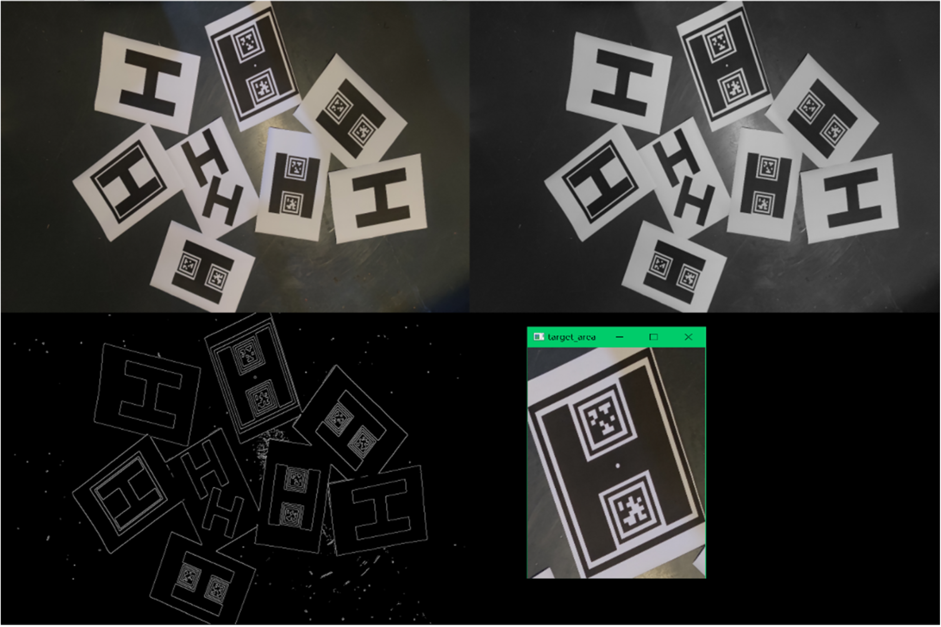
In the visual guidance process, a paper identifier is used to simulate the docking surface and explore the identifier recognition under different conditions. The white point is the actual center point, and the red point is the result recognized by the visual system (Figures 12–14).

Identification of guidance systems in different environments.

Identification of signage guided by the system under different degrees of obstruction.

The recognition of target objects by cameras at different angles.
Accuracy verification
During the end docking process, this paper incorporates depth information obtained from the D435i camera to further refine the pose information obtained by the visual system, thereby maintaining end docking accuracy within 6 mm. Both end docking accuracy comparison experiments and onboard comparison experiments were conducted.
There are many error factors that affect the performance of structured light vision sensor systems, 37 including errors caused by the hardware system structure parameters of the sensor, laser speckle noise errors, and lens distortion errors. When the wavelength of the structured light is significantly different from the surface roughness of the object being detected, optical interference causes random fluctuations in the image points, resulting in laser speckle noise. These fluctuations also cause significant fluctuations in depth information when the camera is at a distance from the object being detected (at a distance of 600 mm, the detection result can fluctuate within an error range of ±2–4 mm), with the error increasing proportionally with distance. In order to conduct accuracy verification experiments on the ground, a depth camera was fixed on a slide rail and camera bracket, with an object placed at one end. The slide rail was slowly moved and the true distance between the camera and the object was physically measured, while the output depth value and monocular ranging value were read. Gaussian functions were used to fit the data obtained from the three methods, and the ranging data curve was obtained, as shown in Figure 15.

Accuracy results of ground validation depth camera and monocular vision ranging.
According to the scatter plot of experimental data, which was fitted by a Gaussian curve, it can be found that the depth camera has an advantage over monocular vision ranging when the distance is within 500 mm. However, after the distance interval of 500 to 600 mm, the advantage of the depth camera's accuracy no longer exists, and the error rapidly increases. When the distance exceeds 600 mm, although the error value of the fitting curve of monocular vision ranging is relatively low, the fluctuation range is large and the stability is reduced.
To compare the stability of three methods in the actual process of unmanned aerial vehicle landing and docking, this paper applied three methods including GNSS ranging module, monocular vision ranging, and depth information ranging to obtain experimental values. A total of 20 experiments were conducted, with the results of the third experiment shown in Figure 16.

Comparison of ranging results.
It can be observed that the GNSS ranging module has poor sensitivity, low feedback frequency, and a minimum detection unit of 0.1 m. Therefore, it cannot serve as a data source for the docking guidance system. However, its advantage lies in its good linearity, which can stably output height information. Visual ranging can accurately output actual height information during actual flight, with an accuracy controlled within centimeters. However, due to the shaking problem of the drone, there may be cases where the landmark moves out of the field of view as the distance gradually decreases. There is no loss of depth information, and the accuracy is higher than that of the visual ranging system within the end (<600 mm), and the stability is good.
During unmanned aerial vehicle docking, the estimation of three-dimensional attitude angles is necessary data for the flight control system, and its accuracy greatly affects the docking result. The estimation of pitch angle, roll angle, and yaw angle is based on the same intrinsic matrix, so the accuracy of one angle measurement can be used to infer the estimation results of the other two angles (as shown in Figure 17). In the actual experiment, the marker was placed in the vehicle model, and the orientation datum was placed in the image. The true value was calculated by measuring the angle between the image-marker-orientation reference benchmark, and then compared with the measured value output by the vision system and the angle derived from the GPS module. A total of 20 experiments were carried out, and the data of the eighth experiment were measured to obtain Figure 18.
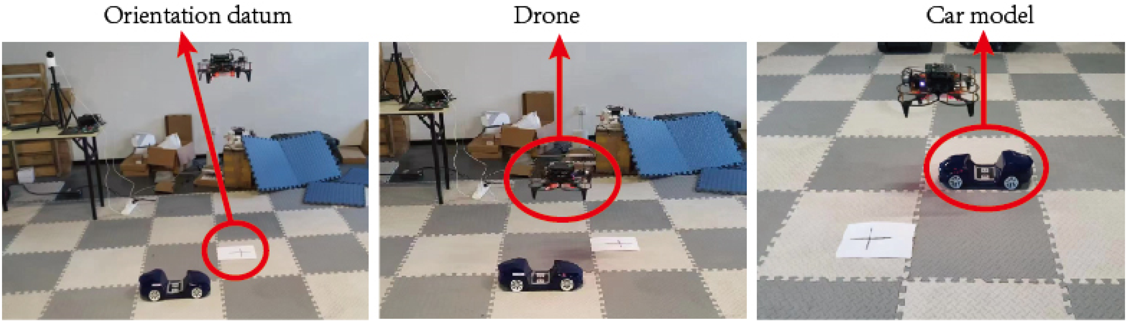
Schematic diagram of the angle measurement experiment scene.

Comparison of vision guidance system and GPS system.
The comparative experiment shows that the visual guidance system can provide highly precise angle information due to the large distance between the center points of the dual codes. During the entire experiment, the GPS error value was around 12°, while the visual guidance system could stably control the error value within 0.5°. Thus, the visual guidance system exhibits a significant advantage in detecting angles and provides better data support for estimating the three-dimensional attitude angle of the onboard computer.
Comparison experiment of landing point accuracy
No matter which guidance method is applied to the real docking and landing scene of the split flying car, it can only bring a certain improvement in accuracy. The final landing accuracy is also affected by many factors such as flight control, UAV hardware, environmental wind, and so on. However, under the same conditions, landing accuracy can be maximized by changing the guidance method. The effect of various guidance methods on improving accuracy can be obtained intuitively through experiments. The drone takes off from a fixed location, and flies in any direction for any distance each time. The landing points are obtained by GPS and the guidance system respectively. The accuracy advantage of the guidance system can be visualized by counting the position and angle deviation between the landing point and the take-off origin. The landing point experiment was carried out on the circular target, and the two guidance methods were used to complete 20 take-offs and landings respectively, the invalid data with excessive errors were removed, and the relative position of the landing point and the final landing orientation of the UAV were retained. The following drop point diagram is obtained, as shown in Figure 19.
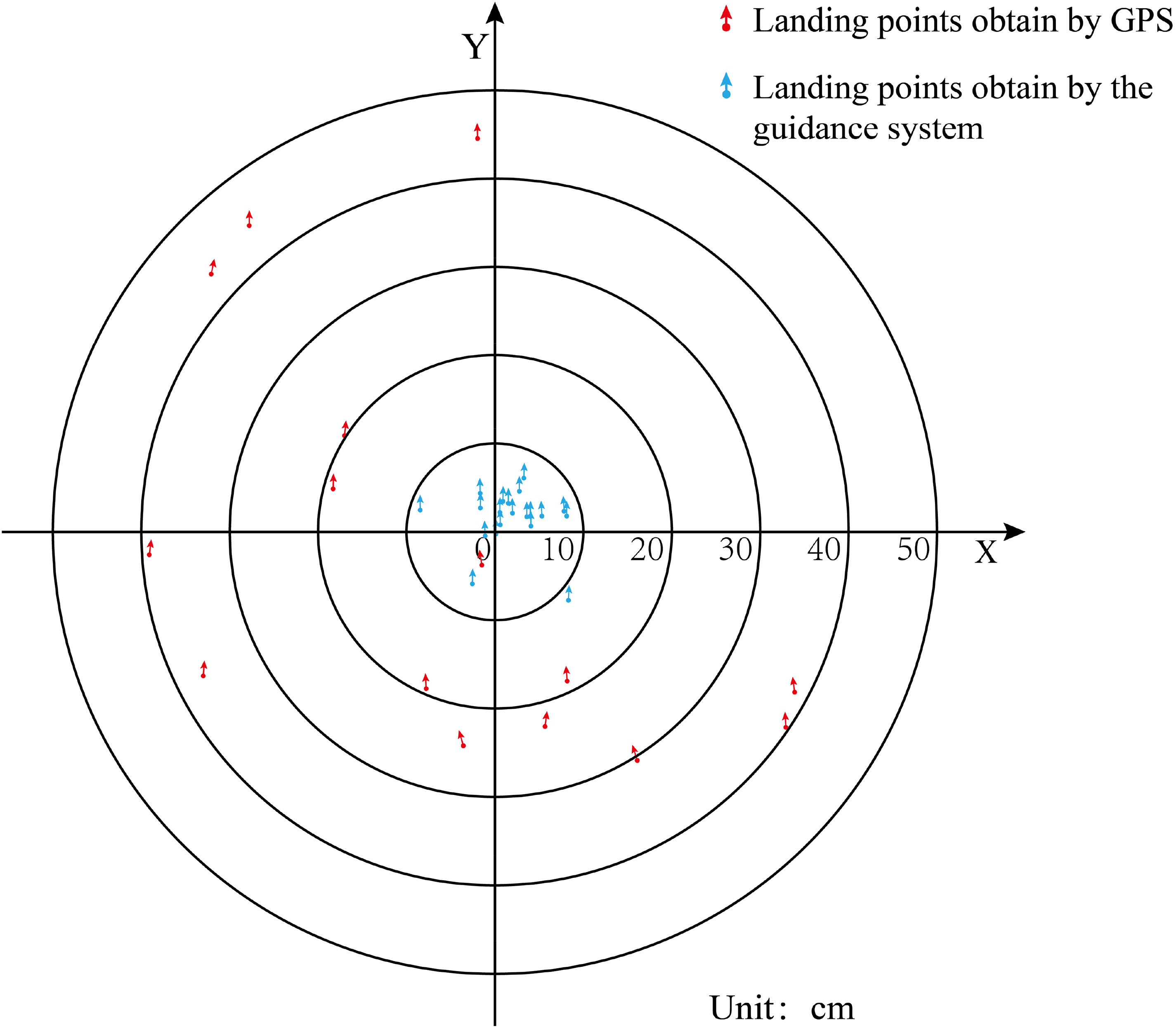
Comparison of landing points for different guidance methods.
It can be found that the guidance system proposed in this paper has high precision. Under the interference of flight control, UAV hardware, environment and other factors, it can still control the position error within 10 cm, most of the landing points are within 5 cm error, and the direction error Within 1°, which can meet the docking requirements.
Conclusion
In order to achieve precise docking between a UAV and a ground vehicle in a modular flying car, this study proposes a multilevel identification marker based on dual Apriltag codes for adaptive target matching at different distances. The proposed three-dimensional position and attitude detection algorithm integrates visual and depth information to output millimeter-level accuracy pose information under different environments, inclinations, and occlusions, meeting the high precision and stability requirements of UAV docking scenarios.
The designed marker can provide “border- H pattern-double code” information in layers according to the distance, which is suitable for complex scenes such as occlusion, strong light, and large angle inclination. It accurately feedbacks the position even when 50% of the area is occluded. The double Apriltag code has 8 corner points, and combined with the 12 corner points information of the “H” shape, it can provide a more stable center point coordinate than a single code when the drone is shaking.
The depth information is integrated into the three-dimensional pose obtained by the vision system, and the Apriltag center pixel coordinates obtained by the color flow are mapped to the depth image. The depth information is used to correct the conversion formula from the world coordinate system to the pixel coordinate system, which can significantly improve the recognition accuracy and stability. This effectively avoids the problem that the single visual information may cause the near-end target to be too large to be recognized. Even if the target is lost, the final docking can still be completed through the depth information.
Footnotes
Declaration of conflicting interests
The authors declared no potential conflicts of interest with respect to the research, authorship, and/or publication of this article.
Funding
The authors disclosed receipt of the following financial support for the research, authorship, and/or publication of this article: This work has been supported by the Natural Science Foundation of Chongqing (Grant No. CSTB2023NSCQ-MSX0802), the Science and Technology Research Program of Chongqing Municipal Education Commission (Grant Nos. KJQN202201105, KJQN202201113).
Data availability statement
Data sharing is not applicable to this article as no datasets were generated or analyzed during the current study.